POWER HACKSAWS MODEL No: SM16/1, SM17/1 ... - CCW-Tools
POWER HACKSAWS MODEL No: SM16/1, SM17/1 ... - CCW-Tools
POWER HACKSAWS MODEL No: SM16/1, SM17/1 ... - CCW-Tools

You also want an ePaper? Increase the reach of your titles
YUMPU automatically turns print PDFs into web optimized ePapers that Google loves.
1.<br />
SAFETY INSTRUCTIONS<br />
INSTRUCTIONS FOR:<br />
<strong>POWER</strong> <strong>HACKSAWS</strong><br />
<strong>MODEL</strong> <strong>No</strong>: <strong>SM16</strong>/1, <strong>SM17</strong>/1, SM18/1<br />
Thank you for purchasing a Sealey quality product. Manufactured to a high standard this product will, if used according to these instructions<br />
and properly maintained, give you years of trouble free performance.<br />
IMPORTANT BEFORE USING THIS PRODUCT, PLEASE READ THE INSTRUCTIONS CAREFULLY. MAKE CAREFUL NOTE OF SAFETY<br />
INSTRUCTIONS, WARNINGS AND CAUTIONS. THIS PRODUCT SHOULD ONLY BE USED FOR ITS INTENDED PURPOSE. FAILURE TO DO SO<br />
MAY CAUSE DAMAGE AND/OR PERSONAL INJURY AND WILL INVALIDATE THE WARRANTY. KEEP THESE INSTRUCTIONS SAFE.<br />
1.1. ELECTRICAL SAFETY<br />
WARNING! It is the responsibility of the owner and the operator to read, understand and comply with the following:<br />
You must check all electrical products, before use, to ensure that they are safe. You must inspect power cables, plugs, sockets and any other<br />
connectors for wear or damage. You must ensure that the risk of electric shock is minimised by the installation of appropriate safety devices.<br />
A Residual Current Circuit Breaker (RCCB) should be incorporated in the main distribution board. We also recommend that a Residual Current<br />
Device (RCD) is used. It is particularly important to use an RCD with portable products that are plugged into a supply which is not protected<br />
by an RCCB. If in any doubt consult a qualified electrician. You may obtain a Residual Current Device by contacting your Sealey dealer.<br />
You must also read and understand the following instructions concerning electrical safety.<br />
1.1.1. The Electricity at Work Act 1989 requires all portable electrical appliances, if used on business premises, to be tested by a qualified<br />
electrician, using a Portable Appliance Tester (PAT), at least once a year.<br />
1.1.2. The Health & Safety at Work Act 1974 makes owners of electrical appliances responsible for the safe condition of those appliances<br />
and the safety of the appliance operators. If in any doubt about electrical safety, contact a qualified electrician.<br />
1.1.3. Ensure that the insulation on all cables and on the appliance is safe before connecting it to the power supply. See 1.1.1. and 1.1.2.<br />
and use a Portable Appliance Tester.<br />
1.1.4. Ensure that cables are always protected against short circuit and overload.<br />
Yellow & Green<br />
1.1.5. Regularly inspect power supply cables and plugs for wear or damage and check all<br />
connections to ensure that none is loose.<br />
Earth Wire<br />
1.1.6. Important: Ensure that the voltage marked on the appliance matches the power supply<br />
to be used and that the plug is fitted with the correct fuse - see fuse rating at right.<br />
1.1.7. DO NOT pull or carry the appliance by the power cable.<br />
Blue<br />
1.1.8. DO NOT pull the plug from the socket by the cable.<br />
Neutral<br />
1.1.9. DO NOT use worn or damaged cables, plugs or connectors. Immediately have any faulty<br />
item repaired or replaced by a qualified electrician. When an ASTA/BS approved UK<br />
3 pin plug is damaged, cut the cable just above the plug and dispose of the plug safely.<br />
Fit a new plug according to the following instructions (UK only).<br />
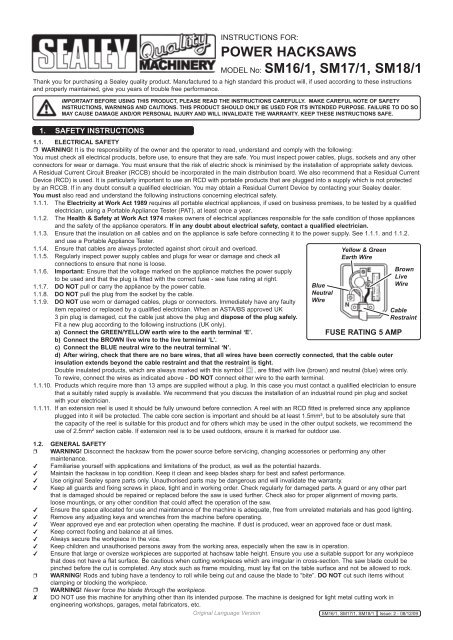
a) Connect the GREEN/YELLOW earth wire to the earth terminal ‘E’.<br />
b) Connect the BROWN live wire to the live terminal ‘L’.<br />
c) Connect the BLUE neutral wire to the neutral terminal ‘N’.<br />
Wire<br />
FUSE RATING 5 AMP<br />
d) After wiring, check that there are no bare wires, that all wires have been correctly connected, that the cable outer<br />
Brown<br />
Live<br />
Wire<br />
Cable<br />
Restraint<br />
insulation extends beyond the cable restraint and that the restraint is tight.<br />
Double insulated products, which are always marked with this symbol , are fitted with live (brown) and neutral (blue) wires only.<br />
To rewire, connect the wires as indicated above - DO NOT connect either wire to the earth terminal.<br />
1.1.10. Products which require more than 13 amps are supplied without a plug. In this case you must contact a qualified electrician to ensure<br />
that a suitably rated supply is available. We recommend that you discuss the installation of an industrial round pin plug and socket<br />
with your electrician.<br />
1.1.11. If an extension reel is used it should be fully unwound before connection. A reel with an RCD fitted is preferred since any appliance<br />
plugged into it will be protected. The cable core section is important and should be at least 1.5mm², but to be absolutely sure that<br />
the capacity of the reel is suitable for this product and for others which may be used in the other output sockets, we recommend the<br />
use of 2.5mm² section cable. If extension reel is to be used outdoors, ensure it is marked for outdoor use.<br />
1.2. GENERAL SAFETY<br />
WARNING! Disconnect the hacksaw from the power source before servicing, changing accessories or performing any other<br />
maintenance.<br />
Familiarise yourself with applications and limitations of the product, as well as the potential hazards.<br />
Maintain the hacksaw in top condition. Keep it clean and keep blades sharp for best and safest performance.<br />
Use original Sealey spare parts only. Unauthorised parts may be dangerous and will invalidate the warranty.<br />
Keep all guards and fixing screws in place, tight and in working order. Check regularly for damaged parts. A guard or any other part<br />
that is damaged should be repaired or replaced before the saw is used further. Check also for proper alignment of moving parts,<br />
loose mountings, or any other condition that could affect the operation of the saw.<br />
Ensure the space allocated for use and maintenance of the machine is adequate, free from unrelated materials and has good lighting.<br />
Remove any adjusting keys and wrenches from the machine before operating.<br />
Wear approved eye and ear protection when operating the machine. If dust is produced, wear an approved face or dust mask.<br />
Keep correct footing and balance at all times.<br />
Always secure the workpiece in the vice.<br />
Keep children and unauthorised persons away from the working area, especially when the saw is in operation.<br />
Ensure that large or oversize workpieces are supported at hachsaw table height. Ensure you use a suitable support for any workpiece<br />
that does not have a flat surface. Be cautious when cutting workpieces which are irregular in cross-section. The saw blade could be<br />
pinched before the cut is completed. Any stock such as frame moulding, must lay flat on the table surface and not be allowed to rock.<br />
WARNING! Rods and tubing have a tendency to roll while being cut and cause the blade to “bite”. DO NOT cut such items without<br />
clamping or blocking the workpiece.<br />
WARNING! Never force the blade through the workpiece.<br />
DO NOT use this machine for anything other than its intended purpose. The machine is designed for light metal cutting work in<br />
engineering workshops, garages, metal fabricators, etc.<br />
Original Language Version <strong>SM16</strong>/1, <strong>SM17</strong>/1, SM18/1 Issue: 2 - 08/12/09
WARNING! These hacksaws must not be used to cut non-metallic materials (including wood) as to do so will invalidate your insurance<br />
cover and your warranty and may cause damage and/or personal injury.<br />
DO NOT wear loose or ill-fitting clothing. Remove ties, watches, rings and other jewellery. Tie up, or adequately cover, long hair.<br />
DO NOT start machine until workpiece is secure and the blade has been lowered to just above the workpiece.<br />
DO NOT use the hacksaw with the blade guard or pulley cover removed.<br />
DO NOT use damaged or deformed hacksaw blades.<br />
Turn the saw off before raising the blade.<br />
DO NOT run the saw with the blade in the raised position.<br />
DO NOT use the machine in wet or damp locations.<br />
DO NOT use the machine in areas where fumes from paint, solvents, or flammable liquids pose a potential hazard. Keep all<br />
flammable materials (including wipers or cleaning rags) away from the saw, and dispose of according to local regulations.<br />
DO NOT stand on the machine.<br />
DO NOT leave machine running unattended. Turn power switch ‘Off’ and do not leave area until machine has come to a complete stop.<br />
DO NOT operate the saw when you are tired, under the influence of alcohol, drugs or intoxicating medication.<br />
2. INTRODUCTION & SPECIFICATIONS<br />
2.1. Introduction.<br />
The <strong>SM16</strong>/1, <strong>SM17</strong>/1 and SM18/1 power hacksaws are manufactured to comply with Supply of Machinery (Safety)<br />
Regulations 1992 (S.I.3073). Cast base with integral mitring vice and setting bar for repetition cutting. Machined<br />
saw arm runners with wear shims for smooth cutting performance. Automatic power cut-off stops machine after<br />
completion of cutting. Fitted with heavy duty 230Volt single phase electric motor and an approved 3 pin safety plug.<br />
<strong>SM17</strong>/1 and SM18/1 supplied with a belt driven coolant pump system to lubricate and cool the workpiece. Fully<br />
guarded pulley and drive assembly.<br />
2.2. Specifications<br />
Model <strong>No</strong> <strong>SM16</strong>/1 <strong>SM17</strong>/1 SM18/1<br />
Capacity at 90º (mm) 180 X 180 185 X 185 205 X 205<br />
Capacity at 45º (mm) 90 X 180 90 X 185 110 X 205<br />
Motor 375W 230V 375W 230V 375W 230V<br />
Size of blade 400 X 25 X 1.25mm 400 X 25 X 1.25mm 400 X 32 X 1.6mm<br />
Cutting speed 50/70 strokes/min 50/70 strokes/min 60/80 strokes/min<br />
Working floor area required 1020 X 350mm 1020 X 350mm 1050 X 370mm<br />
Weight 110kg 115kg 140kg<br />
3. ASSEMBLY AND SET UP CHECKS<br />
<strong>No</strong>te: Letters in brackets refer to Fig.1.<br />
Fig.1.<br />
3.1. Glass oiler<br />
3.1.1. The glass oiler ensures constant lubrication between the bow saw and the saw arm.<br />
3.1.2. Screw the glass oiler into the mounting on the saw bow, as shown in (A).<br />
3.1.3. Fill the oiler with light machine oil.<br />
3.1.4. Adjust the rate of flow by turning the serrated collar on the top of the oiler.<br />
3.2. Oil caps<br />
3.2.1. There are five oil caps fitted to the saw, (B1 - B5).<br />
3.2.2. Remove the six self tapping screws in the guard, (C, only two shown) and fold it<br />
down.<br />
3.2.3. Identify the two oil caps on the frame support (B1 & B2) and the two on the saw<br />
arm, (B3 & B4).<br />
3.2.4. Lift each cap in turn and fill the cups with light machine oil. Allow time for the oil<br />
to penetrate and refill as necessary.<br />
3.2.5. Fold the guard into position and refit the six screws removed in paragraph 3.2.2.<br />
3.2.6. The fifth oil cap is fitted on the connecting rod, (B5). Lift the cap and fill the cup<br />
with light machine oil.<br />
3.3. Length bar<br />
3.3.1. When cutting multiple same length pieces, the length bar and length plate can be<br />
fitted to save the operator having to measure the item to be cut each time.<br />
3.3.2. Screw the length bar (D) into the side of the saw bed and tighten the locking nut.<br />
3.3.3. Adjust the length plate (E) to the required position and lock in place by<br />
tightening the “T” head bolt (F).<br />
3.4. Blade tension<br />
3.4.1. Check the blade tension by flicking the blade. The blade should make a sharp<br />
pining sound if it is properly adjusted.<br />
3.4.2. If the blade needs adjusting, refer to paragraph 5.3.<br />
3.5. Coolant tank (Models <strong>SM17</strong>/1 and SM18/1 only)<br />
3.5.1. Fill the cooling tank, attached to the underside of the saw bed, with cutting oil<br />
by pouring through the slots in the saw bed into the coolant tank. Ensure the supply tap at the base of the coolant pipe is turned off.<br />
<strong>No</strong>te: Neat cutting oil, part no NCO/5L and soluble cutting oil SCO/5L are available from your local Sealey dealer.<br />
3.6. Saw arm weight<br />
3.6.1. Fit the saw arm weight, (G) onto the saw arm to increase the cutting weight if required.<br />
Original Language Version <strong>SM16</strong>/1, <strong>SM17</strong>/1, SM18/1 Issue: 2 - 08/12/09
4. OPERATION<br />
WARNING! Before operating the hacksaw ensure that you read, understand and apply the safety instructions in Section 1.<br />
NOTE: Before operating the machine certain checks and adjustments will need to be carried out. It is very important that<br />
these instructions are followed carefully in order that the machine is set up safely and correctly.<br />
WARNING! The machine is designed for the cutting of light metal in engineering workshops, garages, metal fabricators, etc. The<br />
<strong>SM16</strong>/1, <strong>SM17</strong>/1 & SM18/1 must not be used to cut any other materials (including wood). To do so will invalidate your insurance<br />
cover and your warranty and may cause damage and/or personal injury.<br />
WARNING! Ensure that the saw is disconnected from the power supply before making any adjustments.<br />
4.1. Set up checks<br />
4.1.1. Check the saw thoroughly before using it. Ensure the guards are correctly fitted and that the moving parts are secure and in working<br />
order.<br />
4.1.2. Raise the saw arm as far as possible.<br />
4.1.3. Place the work piece in the vice, set the length bar as required and clamp the work piece securely. For angled cutting, see 4.2.<br />
4.1.4. If cutting mild steel, turn on the coolant supply tap (models <strong>SM17</strong>/1 and SM18/1 only) and direct the coolant nozzle towards the area of<br />
the workpiece that will be cut.<br />
<strong>No</strong>te: Ensure the oiler is correctly set and tha t oil has been applied to the five oil caps before starting the saw.<br />
4.1.4. Connect the machine to the mains power supply.<br />
4.1.5. Start the machine and the arm will automatically lower and start cutting.<br />
4.1.6. When sawing is completed the saw will switch off automatically, disconnect from the power supply, raise blade and remove workpiece.<br />
Never raise blade when machine is running .<br />
4.2. Vice setting<br />
4.2.1. The vice is locked at 0º but can be set to any angle up to 45º.<br />
4.2.2. To set an angle on the vice, remove the centre bolt fig.2.C and vice clamp bolt<br />
fig.2.D.<br />
4.2.3. Loosen the vice swivel bolt fig.2.A and the vice clamp bolt fig.2.B.<br />
4.2.4. Set the vice to the required angle and tighten vice swivel bolt fig.2.A and the vice<br />
clamp bolt fig.2.B.<br />
4.2.5. Loosen the free vice clamp bolt fig.2.E.<br />
4.2.6. Place the work piece in the vice and wind the free vice closed until it grips the<br />
workpiece.<br />
4.2.7. Tighten the free vice clamp bolt fig.2.E and ensure the workpiece is securely<br />
clamped.<br />
4.2.8. Where the length of the workpiece to be secured is half the width if the vice, or less,<br />
adjust the bolt on the free vice so that it touches the fixed vice face, as shown in<br />
fig.3.<br />
4.2.9. The saw bed provides an alternative pair of mounting holes for the fixed side of the<br />
vice. o use these holes, remove the centre bolt fig2.C, the vice clamp bolts<br />
fig.2.B & D and the vice swivel bolt fig.2.A.<br />
4.2.10. Position the fixed side of the vice on the saw bed such that the vice swivel bolt fig.2.A<br />
is located through the vice and into the mounting hole fig.2.F.<br />
4.2.11. Fit one of the vice clamp bolts fig.2.B or D through the vice and into mounting hole<br />
fig.2.G.<br />
<strong>No</strong>te: When using these alternative mounting holes, the fixed vice does not have a 0º lock<br />
facility. It is the responsibility of the operator to ensure that the fixed vice is at the<br />
correct angle.<br />
4.2.12. Set the vice to the required angle and secure by tightening the vice swivel fig.2.A and<br />
clamp bolt fig.2.D.<br />
<strong>No</strong>te: Use of these alternative mounting holes can lengthen the life of the saw blades.<br />
Fig.2.<br />
Fig.3.<br />
5. MAINTENANCE & ADJUSTMENTS<br />
WARNING! BEFORE CARRYING OUT ANY MAINENANCE OR MAKING ANY<br />
ADJUSTMENTS, DISCONNECT SAW FROM <strong>POWER</strong> SUPPLY.<br />
5.1. Cleaning<br />
5.1.1. Clean saw after each operation and smear unpainted surfaces with oil to prevent<br />
rusting.<br />
5.2. Replacing the saw blade<br />
We recommend you keep a small supply of commonly used saw blades to hand.<br />
Change saw blades frequently for best results. Ensure you choose a blade with a<br />
pitch suitable for workpiece to be cut.<br />
5.2.1. Disconnect the machine from the power supply.<br />
5.2.2. Loosen the two screws, fig.4.A, holding the fixed plate on.<br />
5.2.3. Undo the two locking nuts, fig.4.B and release the tension in the blade.<br />
5.2.4. Undo the two blade retaining screws, fig.4.C and remove the blade.<br />
5.2.5. Fitting the new blade is the reverse of the procedure in paragraphs 5.4.1. to 5.4.3.<br />
5.2.6. Tension the blade as described in paragraph 5.5.<br />
5.3. Blade tension<br />
5.3.1. Test the blade tension by flicking the blade. The blade should make a sharp pinging<br />
sound if it is correctly adjusted.<br />
5.3.2. To adjust the blade tension, turn the lock nuts fig.4.B. Do not over tighten.<br />
5.4. Blade stroke adjustment<br />
5.4.1. Disconnect the machine from the power supply.<br />
5.4.2. The sawblade stroke can be adjusted ±60mm.<br />
5.4.3. Remove the six self tapping screws in the guard, fig.1.C and fold it down.<br />
5.4.4. Loosen the nut on the inside of the gear wheel, fig.5.<br />
Fig.4.<br />
Fig.5.<br />
Original Language Version <strong>SM16</strong>/1, <strong>SM17</strong>/1, SM18/1 Issue: 2 - 08/12/09
5.4.5. To shorten the stroke, slide the bow saw towards the centre of the gear wheel and<br />
to lengthen the stroke, slide the bow saw towards the outside of the gear wheel.<br />
5.4.6. Tighten the nut on the inside of the gear wheel, fig.5.<br />
5.4.7. When satisfied that the adjustment is accurate, carefully turn the pulley by hand to<br />
see if the blade snags or rubs at any point. Readjust stroke if necessary.<br />
5.4.8. Fold the guard into position and refit the six screws removed in paragraph 5.4.3.<br />
5.5. Hydraulic pump - oil change<br />
5.5.1 The oil in the hydraulic pump should be changed every 6 months.<br />
5.5.2. Remove the six self tapping screws in the guard, fig.1.C and fold it down.<br />
5.5.3. Remove the cotter pin, fig.6.A and the compression arm retaining pin, fig.6.B.<br />
5.5.4. Lift off the compression arm, fig.6. C.<br />
5.5.5. Remove the cotter pin, fig.6. D and the swing bolt retaining pin, fig.6.E.<br />
5.5.6. Loosen the two hydraulic pump retaining bolts, fig.6.F and lift out the hydraulic<br />
pump.<br />
5.5.7. Undo the four screws in the hydraulic pump top plate (not shown), lift the plate off<br />
and empty the oil into a suitable container and dispose of according to local<br />
regulations.<br />
5.5.8. Refill the pump with oil.<br />
<strong>No</strong>te: Use a good quality jack oil, such as SEALEY HYDRAULIC JACK OIL.<br />
5.5.9. Assembly and fitting instructions are the reverse of paragraphs 5.5.2. to 5.5.7.<br />
above.<br />
5.6. Bow saw & saw arm adjustment<br />
5.6.1. Play between the bow saw and the saw arm can be removed by adjusting the three<br />
tensioning bolts shown in fig.7.<br />
5.6.2. Loosen the three lock nuts and tighten the tensioning bolts until the play has been<br />
removed.<br />
5.6.3. Tighten the three lock nuts.<br />
<strong>No</strong>te: Do not over tighten the tensioning bolts as this will cause excessive wear.<br />
5.7. Vibration<br />
5.7.1. If the saw arm shakes, vibrates excessively or apears otherwise insecure it may be<br />
necessary to tighten the support frame,fig.8 to the gear shaft or tighten the saw<br />
arm to the support frame fig.9.<br />
5.7.2. To tighten the support, remove the six self tapping screws in the guard, fig.1.C and<br />
fold it down.<br />
5.7.3. Loosen the lock nuts and tighten the bolts fig.8 such that any movement on the<br />
gear shaft is significantly reduced.<br />
5.7.4. Tighten the lock nuts.<br />
5.7.5. Fold the guard into position and refit the six screws removed in paragraph 5.7.2.<br />
<strong>No</strong>te: Do not over tighten the bolts as this will cause excessive wear.<br />
5.7.6 To tighten the support, remove the six self tapping screws in the guard, fig.1.C and<br />
fold it down.<br />
5.7.7. Loosen the outer lock nut, fig.9, tighten the inner lock nut and tighten the outer lock<br />
nut.<br />
5.7.8. Fold the guard into position and refit the six screws removed in paragraph 5.7.6.<br />
5.7. Adjusting rate of decent of the saw arm<br />
5.7.1. The rate of decent of the saw arm can be adjusted by altering the effective length of<br />
the compressing bracket.<br />
5.7.2. Remove the six self tapping screws in the guard, fig.1.C and fold it down.<br />
5.7.3. To increase the rate of decent of the saw arm, loosen lock nut “A”, fig.10, and<br />
tighten lock nut “B”, fig.10 shortening the effective length of the compressing<br />
bracket.<br />
5.7.4. To decrease the rate of decent of the saw arm, loosen lock nut “B”, fig.10 and<br />
tighten lock nut “A”, fig.10 increasing the effective length of the compressing<br />
bracket.<br />
5.7.5. Fold the guard into position and refit the six screws removed in paragraph 5.7.2.<br />
<strong>No</strong>te: Fine adjustment of the rate of decent of the saw arm is possible using the fine<br />
adjuster, fig.11, on the hydraulic pump (SM18/1 only).<br />
Fig.6.<br />
Fig.7.<br />
Fig.9.<br />
Fig.8.<br />
Fig.10.<br />
Fig.11.<br />
Original Language Version <strong>SM16</strong>/1, <strong>SM17</strong>/1, SM18/1 Issue: 2 - 08/12/09
6. TROUBLESHOOTING<br />
Problem Possible Cause Solution<br />
The angle of the cut is inaccurate. 1. The tensioning bolts on the bow are loose. 1. Tighten the bolts.<br />
2. The blade is not tight. 2. Tighten the blade.<br />
3. The blade is dull. 3. Replace the blade.<br />
4. The setting on the vice is inaccurate. 4. Set the vice at 0 using a right angle<br />
and adjust the pointer to match.<br />
<strong>No</strong> power 1. Oil level is low. 1. Check oil and fill up as required.<br />
2. The tensioning bolts are loose. 2. Tighten the bolts.<br />
Saw is not cutting efficiently. 1. Pressure from the saw arm is too light. 1. Attach a heavier weight to the arm.<br />
2. The stroke of the blade is incorrect. 2. Adjust the stroke.<br />
3. Saw blade is the wrong type. 3. Use a different TPI blade.<br />
4. Saw blade is worn. 4. Replace the blade.<br />
Saw blade does not rise when cutting. 1. Hydraulic pressure is low. 1. Check the pressure. Refill if needed.<br />
2. Compressing arm is too low. 2. Adjust the compressing bracket to a<br />
higher position.<br />
3. The cam is loose. 3. Tighten the cam.<br />
4. Air is in the hydraulic system. 4. Pump the arm a few times manually.<br />
Excessive noise. 1. The saw is low on lubricant. 1. Check lubricant and refill as required.<br />
2. The pulley is touching the pulley guard. 2. Adjust the pulley so that it does not touch<br />
the guard.<br />
3. The gears are worn out. 3. Replace the gears.<br />
4. Screws, bolts or other moving parts are loose. 4. Tighten loose parts as required.<br />
Coolant delivery is weak. 1. Sediment may have collected in the cooling 1. Clean the cooling tank .<br />
tank.<br />
NOTE: It is our policy to continually improve products and as such we reserve the right to alter data, specifications and component parts without prior notice.<br />
IMPORTANT: <strong>No</strong> liability is accepted for incorrect use of this product.<br />
WARRANTY: Guarantee is 12 months from purchase date, proof of which will be required for any claim.<br />
INFORMATION: For a copy of our latest catalogue and promotions call us on 01284 757525 and leave your full name and address, including postcode.<br />
Sole UK Distributor, Sealey Group,<br />
Kempson Way, Suffolk Business Park,<br />
Bury St. Edmunds, Suffolk,<br />
IP32 7AR<br />
01284 757500<br />
Web<br />
www.sealey.co.uk<br />
01284 703534 email sales@sealey.co.uk<br />
Original Language Version <strong>SM16</strong>/1, <strong>SM17</strong>/1, SM18/1 Issue: 2 - 08/12/09