MicroTab Light LED Display User Manual - FinishLynx
MicroTab Light LED Display User Manual - FinishLynx
MicroTab Light LED Display User Manual - FinishLynx

Create successful ePaper yourself
Turn your PDF publications into a flip-book with our unique Google optimized e-Paper software.
<strong>User</strong> <strong>Manual</strong><br />
Version 1.0.0
Contents<br />
1 Hardware ............................................................................................................................................................. 3<br />
1.1 Control Panel ...................................................................................................................... 4<br />
1.2 Connections ......................................................................................................................... 5<br />
1.3 Power supply ...................................................................................................................... 6<br />
1.3.1.1 Battery Charging ................................................................................................... 6<br />
1.4 Firmware Updating ............................................................................................................ 8<br />
1.5 Hardware Reset .................................................................................................................. 9<br />
1.6 Brightness Sensor ............................................................................................................. 10<br />
2 Internal Programs .......................................................................................................................................... 11<br />
2.1 General Setup .................................................................................................................... 12<br />
2.2 Base Program .................................................................................................................... 13<br />
2.2.1 Setup .............................................................................................................................. 13<br />
2.3 Timer (Chronometer) ...................................................................................................... 14<br />
2.3.1 Setup .............................................................................................................................. 14<br />
2.4 Clock .................................................................................................................................. 16<br />
2.4.1 Setup .............................................................................................................................. 16<br />
2.5 Date & Clock ...................................................................................................................... 17<br />
2.5.1 Setup .............................................................................................................................. 17<br />
2.6 Test Pixel ........................................................................................................................... 18<br />
Microgate <strong>MicroTab</strong> Led <strong>Light</strong> <strong>User</strong> <strong>Manual</strong> Page 2 of 19
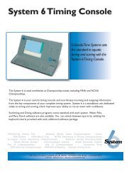
1 HARDWARE<br />
Figure 1 - <strong>MicroTab</strong> Led <strong>Light</strong><br />
‣ Single display board<br />
‣ Matrix: 16 x 64 <strong>LED</strong>s<br />
‣ Dimensions: 16 x 64 x 15 cm (H x W x D)<br />
‣ Weight: approx. 3,5 kg<br />
‣ Controllable via: RS232, RS485<br />
‣ USB port for internal flash programming<br />
Microgate <strong>MicroTab</strong> Led <strong>Light</strong> <strong>User</strong> <strong>Manual</strong> Page 3 of 19
1.1 CONTROL PANEL<br />
LOW BATTERY: Battery status signal <strong>LED</strong>.<br />
SERIAL1: 6-pole Amphenol connector for serial<br />
input/output<br />
START STOP LAP INPUTS: 6-pole Amphenol<br />
connector for START, STOP, and LAP signals<br />
FUSE: Fuse cavity<br />
SPEAKER: Jack connector for external speaker<br />
connection<br />
START STOP: Green START STOP button used<br />
for manual START and STOP signals and for<br />
modifying values in program settings 1<br />
LAP RESET: Yellow LAP RESET button used for<br />
manual LAP signals and for confirming program<br />
settings 2<br />
POWER: On/Off switch<br />
SUPPLY: Neutrik connector for external power<br />
supply and battery charging (if used)<br />
USB: USB cable connector for firmware<br />
updating<br />
1 This button will hereafter be referred to as<br />
Figure 2 – Control panel<br />
START-MODIFY<br />
2 This button will hereafter be referred to as<br />
LAP-SETUP<br />
Microgate <strong>MicroTab</strong> Led <strong>Light</strong> <strong>User</strong> <strong>Manual</strong> Page 4 of 19
1.2 CONNECTIONS<br />
SERIAL 1 Input/Output (6-pole Amphenol)<br />
1 Serial 1 RS232 TX (output)<br />
2 Serial 1 SYNC IN (input)<br />
3 Serial 1 RS485+<br />
4 Serial 1 RS485-<br />
5 Serial 1 GND (cable braiding)<br />
6 Serial 1 RS232 RX (input)<br />
Figure 3 - 6-pole Amphenol connector<br />
START – STOP – LAP Input/Output (6-pole Amphenol)<br />
1 START signal (input)<br />
2 Controlled output 5V, max 500mA (for external device power supply)<br />
3 GND<br />
4 LAP signal (input)<br />
5 STOP signal (input)<br />
6 AUX signal (input)<br />
Microgate <strong>MicroTab</strong> Led <strong>Light</strong> <strong>User</strong> <strong>Manual</strong> Page 5 of 19
1.3 POWER SUPPLY<br />
Power can be supplied in three ways:<br />
• Connecting the <strong>MicroTab</strong> Led <strong>Light</strong> display board to the Microgate network adapter<br />
(code $ACC47). In this way it is possible to supply a mains graphic display board and to<br />
keep the batteries (if used) charged at the same time. This guarantees perfect<br />
functioning also when the mains power supply is interrupted. The $ACC147 network<br />
adapter operates with an input of 50 or 60 Hz alternate current, within a range of 100<br />
and 240 Volts.<br />
• Using the internal batteries of the display board (optional module $ACC163); in this<br />
case autonomy is usually over 8 hours of continuous functioning (depending on the<br />
type of display used).<br />
• Connecting the display board via the DC/DC 12/48V converter (optional module<br />
$ACC174) to any direct current supply (stabilized or not) between 11 and 16 Volts,<br />
which is able to supply at least 100W peak power and approximately 50W average<br />
power. A (60Ah) car battery usually ensures more than 6 hours continuous operation<br />
(depending on the used display type).<br />
IMPORTANT NOTICE: The $ACC47 network adapter is not suitable for outdoor use. Consequently<br />
Microgate is not liable for any damages to persons or things caused by incorrect use of the<br />
network adapter.<br />
1.3.1.1 BATTERY CHARGING<br />
To enter charging mode, press the green 'START MODIFY' button on the control panel for at least 2<br />
seconds with the display board turned off and after having connected an external power source to<br />
the SUPPLY connector. Charging can take up to 10 hours, depending on the initial battery level.<br />
The charging process can be interrupted by pressing again the green 'START MODIFY' button on<br />
the control panel for at least 2 seconds.<br />
The more frequently lithium-ion polymer (Li-poly) batteries are charged, the longer the battery life<br />
will be.<br />
Microgate <strong>MicroTab</strong> Led <strong>Light</strong> <strong>User</strong> <strong>Manual</strong> Page 6 of 19
The LOW BATTERY <strong>LED</strong> on the control panel indicates the battery level, the power source used, and the<br />
charging status (if applicable).<br />
EXTERNAL SUPPLY<br />
STATUS<br />
<strong>Display</strong> board on/off<br />
Batteries charged<br />
<strong>Display</strong> board on/off<br />
Batteries empty<br />
LOW BATTERY <strong>LED</strong><br />
Green – Green – Pause<br />
Green – Red – Pause<br />
INTERNAL SUPPLY (BATTERIES)<br />
STATUS<br />
<strong>Display</strong> board off<br />
Batteries charged/empty<br />
<strong>Display</strong> board on<br />
Batteries charged<br />
<strong>Display</strong> board on<br />
Batteries empty<br />
LOW BATTERY <strong>LED</strong><br />
Off<br />
Green – Pause – Green – Pause<br />
Red – Pause – Red – Pause<br />
CHARGE<br />
STATUS<br />
LOW BATTERY <strong>LED</strong><br />
Batteries charging Pause – Green – Pause – Green FAST<br />
Charging complete Steady green<br />
Microgate <strong>MicroTab</strong> Led <strong>Light</strong> <strong>User</strong> <strong>Manual</strong> Page 7 of 19
1.4 FIRMWARE UPDATING<br />
Each time <strong>MicroTab</strong> Led <strong>Light</strong> is turned on, it displays the firmware version presently stored,<br />
usually with the following syntax: x.y.z (major, minor, revision).<br />
Figure 4 - Firmware version<br />
The firmware can be updated downloading it from the SUPPORT section of the www.microgate.it<br />
website.<br />
Once downloaded the file, please follow the steps below:<br />
<br />
<br />
<br />
<br />
<br />
Turn on the display board and wait until boot is complete.<br />
Connect the USB cable (not supplied) from the display board to a USB port of your PC.<br />
Launch the Updater program following the on-screen instructions. In particular, if the<br />
software does not detect Active Sync (for Windows XP) or Windows Mobile Device Center<br />
(Vista/Windows 7), it suggests a link for downloading and installing it.<br />
Select the option 'Keep existing settings' to maintain all current settings; if you do not<br />
select it, the default values are restored.<br />
After a few minutes the display board is reset automatically displaying the number of the<br />
new installed version.<br />
Figure 5 – Updater Software<br />
Microgate <strong>MicroTab</strong> Led <strong>Light</strong> <strong>User</strong> <strong>Manual</strong> Page 8 of 19
1.5 HARDWARE RESET<br />
If the display board stops responding to commands (e.g. entering the Setup menu as described in<br />
par. 2.1), a Strong Reset can be carried out choosing to reset all values to the default parameters<br />
(Factory Settings).<br />
The steps to carry out are the following:<br />
<br />
<br />
Turn off the display board by pressing the Power (Off) button.<br />
Press simultaneously the START-MODIFY and LAP-SETUP buttons to turn on the display board<br />
(Power -> On)<br />
<br />
<br />
During the first boot phase, when the first 4 <strong>LED</strong>s (2x2) in the upper left corner are blinking,<br />
keep the two buttons pressed.<br />
<br />
When the blinking <strong>LED</strong>s are 6 (3 x 2) release the two buttons.<br />
<br />
After a few moments the software asks if you want to restore the factory settings (Reset<br />
Setting? Yellow=Yes) or use the stored settings. Press LAP-SETUP to reset all values<br />
to the initial conditions.<br />
Microgate <strong>MicroTab</strong> Led <strong>Light</strong> <strong>User</strong> <strong>Manual</strong> Page 9 of 19
1.6 BRIGHTNESS SENSOR<br />
<strong>Display</strong> board <strong>LED</strong> brightness can be set manually (from the menu or software) or assessed<br />
automatically depending on the ambient light detected by the brightness sensor in the upper left<br />
corner (4th row, 5th column). There are other sensors for each 32x32 <strong>LED</strong> area, but only the one in<br />
the upper left corner is used for active control.<br />
The minimum-maximum brightness values range from 1 to 100%, although in the default settings<br />
60 is the maximum value. This means that the maximum brightness value that can be set<br />
automatically by the sensor is 60. Normally this value is enough even in case of strong light or<br />
sunny days. If you want to increase brightness (which causes higher power and battery<br />
consumption), set 1 – 100 as minimum and maximum value so that the sensor can set higher<br />
values. Of course it is possible to set Brightness Type = <strong>Manual</strong> (instead of Automatic) and to<br />
choose a fixed brightness level (see par. 2.1)<br />
Figure 6 – Brightness sensor<br />
Microgate <strong>MicroTab</strong> Led <strong>Light</strong> <strong>User</strong> <strong>Manual</strong> Page 10 of 19
2 INTERNAL PROGRAMS<br />
Besides the 'Base Program', which waits for PC or chronometer commands and displays the<br />
received information, <strong>MicroTab</strong> Led <strong>Light</strong> display boards also have a series of internal programs for<br />
various timing needs.<br />
The programs available at the time of printing this guide are:<br />
Base Program<br />
Timer<br />
Clock<br />
Date & Clock<br />
Test Pixel<br />
Waits for commands via serial cable<br />
Works like a normal 1/100 second precision chronometer.<br />
<strong>Display</strong>s the time of the internal clock of the display board.<br />
<strong>Display</strong>s date and time of the internal clock of the display board.<br />
Checks that the <strong>LED</strong>s work correctly.<br />
To change program follow these steps:<br />
<br />
<br />
<br />
<br />
<br />
Keep the YELLOW LAP-SETUP button pressed for at least 3 seconds.<br />
The currently selected program is displayed.<br />
Press the GREEN START-MODIFY button to scroll down the above-stated program list.<br />
Once the desired program has been reached, press the LAP-SETUP button to confirm.<br />
Depending on the chosen program, further settings may be required or the program is<br />
executed immediately.<br />
Microgate <strong>MicroTab</strong> Led <strong>Light</strong> <strong>User</strong> <strong>Manual</strong> Page 11 of 19
2.1 GENERAL SETUP<br />
Enter the Setup menu of a program (if available) by pressing the yellow LAP-SETUP button for 3<br />
seconds. Once concluded the program configuration the so-called 'Advanced Setup' is displayed,<br />
i.e. the possibility to change the general parameters of the display board applied to all programs.<br />
When Advanced Setup is displayed, press any button and confirm pressing LAP-SETUP to enter the<br />
menu.<br />
The values available for each menu item can be scrolled down with the green START-MODIFY button<br />
and are confirmed by pressing the yellow LAP-SETUP button:<br />
Brightness Type<br />
AUTO | MANUAL<br />
Brightness<br />
1…100%<br />
Set the brightness type. Automatic uses the brightness sensor, whereas<br />
<strong>Manual</strong> uses the level set in the following step<br />
If Brightness Type = MANUAL, set brightness with START-MODIFY. Holding the<br />
button, the numbers increase rapidly<br />
Firmware<br />
x.y.z<br />
Serial Number<br />
xxxxxxxxxxx<br />
The currently loaded firmware version is displayed.<br />
The display board serial number is displayed. Press LAP-Setup to continue<br />
and exit the Advanced Setup menu.<br />
Microgate <strong>MicroTab</strong> Led <strong>Light</strong> <strong>User</strong> <strong>Manual</strong> Page 12 of 19
2.2 BASE PROGRAM<br />
Selecting Base Program <strong>MicroTab</strong> Led <strong>Light</strong> can be controlled via the SERIAL 1 communication<br />
port.<br />
2.2.1 SETUP<br />
Keep the LAP-SETUP pressed for at least 2 seconds to enter the Setup. Press START-MODIFY to change the<br />
displayed values.<br />
Advanced Setup ? Press any key to continue.<br />
Yellow = Yes Press LAP-SETUP to enter the general setup (see par. 2.1)<br />
Green = No<br />
Press START-MODIFY to scroll the setup of the current program<br />
Font<br />
Regular|Narrow<br />
Set the default font (normal or narrow)<br />
Press LAP-SETUP<br />
Row<br />
0...15 Set the row address (0 = first row)<br />
Press LAP-SETUP<br />
Column<br />
0...3 Set column address (0 = first column)<br />
Press LAP-SETUP<br />
X Offset<br />
0...384 Set the number of X Offset <strong>LED</strong>s. All commands (with the ALPHA protocol)<br />
will be shifted to the left by a certain amount of <strong>LED</strong>s.<br />
Press LAP-SETUP<br />
Baud<br />
1200…230400 Set the speed of the serial port applying one of the default values ('1200',<br />
'2400', '4800', '9600', '19200', '38400', '38400', '57600', '115200', '230400').<br />
Press LAP-SETUP<br />
Green to Default<br />
Press the green START-MODIFY button to reset the display board to the<br />
default values, or press the yellow LAP-SETUP button to accept the entered<br />
values.<br />
Microgate <strong>MicroTab</strong> Led <strong>Light</strong> <strong>User</strong> <strong>Manual</strong> Page 13 of 19
2.3 TIMER (CHRONOMETER)<br />
In this mode <strong>MicroTab</strong> Led <strong>Light</strong> works as a typical 1/100 second precision chronometer.<br />
• Pressing Start (manual or from input) the chronometer begins to count.<br />
• With Lap (manual or from input) the chronometer displays an intermediate time for 5<br />
seconds.<br />
• The chronometer is stopped using the manual Start/Stop<br />
• At this point it is possible to reset the chronometer with a further Lap.<br />
Without reset the chronometer starts from the displayed value.<br />
If the AutoReset time has been set, after each Stop (or manual Start) the chronometer is reset<br />
after a given amount of time.<br />
2.3.1 SETUP<br />
Keep the LAP-SETUP pressed for at least 2 seconds to enter the Setup. Press START-MODIFY to change the<br />
displayed values.<br />
Configuration<br />
Normal | Over 24H | Until 24H Set the desired mode:<br />
Normal = the chronometer starts from 0:00<br />
Over 24H = the chronometer continues infinitely and after 24h displays<br />
time as 24:00:01<br />
Until 24H = the chronometer stops after 24h.00.00<br />
Press LAP-SETUP<br />
Advanced Setup ?<br />
Press any key to continue.<br />
Yellow = Yes Press LAP-SETUP to enter the general setup (see par. 2.1)<br />
Green = No<br />
Press START-MODIFY to scroll the setup of the current program<br />
Set Starttime<br />
HH= 0<br />
Set Starttime<br />
MM= 0<br />
Set Starttime<br />
SS= 0<br />
Set Starttime<br />
mm= 0<br />
Set the hours<br />
Press LAP-SETUP<br />
Set the minutes<br />
Press LAP-SETUP<br />
Set the seconds<br />
Press LAP-SETUP<br />
Set the thousandths of a second<br />
Press LAP-SETUP<br />
Microgate <strong>MicroTab</strong> Led <strong>Light</strong> <strong>User</strong> <strong>Manual</strong> Page 14 of 19
Autoreset<br />
Time= 0<br />
Start – Stop<br />
Start – Start<br />
Set the automatic Reset time (in seconds). After a stop command and<br />
when the above-stated time has passed, the chronometer is reset to<br />
zero. An invalid (zero) time disables the Autoreset function.<br />
Press LAP-SETUP<br />
The Start button is used at start and finish<br />
The Start button is used only at start<br />
The chronometer is stopped and shows the preset time, ready to start.<br />
Microgate <strong>MicroTab</strong> Led <strong>Light</strong> <strong>User</strong> <strong>Manual</strong> Page 15 of 19
2.4 CLOCK<br />
This program allows you to display the time of the internal <strong>MicroTab</strong> Led <strong>Light</strong> clock.<br />
2.4.1 SETUP<br />
It is possible to set the date and time of the internal clock.<br />
NOTE: When setting the time, <strong>MicroTab</strong> Led <strong>Light</strong> shows the time of first setting. If no value is modified,<br />
time is not changed and continues to run as if Setup had not been used.<br />
Keep the LAP-SETUP button pressed for at least 2 seconds to enter the Setup. Press START-MODIFY to change<br />
the displayed values.<br />
Configuration<br />
HH:MM:SS | HH:MM<br />
Set display mode with START-MODIFY<br />
Advanced Setup ? Press any key to continue.<br />
Yellow = Yes Press LAP-SETUP to enter the general setup (see par. 2.1)<br />
Green = No<br />
Press START-MODIFY to scroll the setup of the current program<br />
Set R.T. Date<br />
Day = 13<br />
Set R.T. Date<br />
daynum = 3<br />
Set R.T. Date<br />
month = 7<br />
Set R.T. Clock<br />
HH = 0<br />
Set R.T. Clock<br />
MM = 0<br />
Set R.T. Clock<br />
SS = 0<br />
Set the day of the month with START-MODIFY<br />
Press LAP-SETUP<br />
Set the week day with START-MODIFY<br />
(1 Sunday, 2 Monday, ..., 7 Saturday)<br />
Press LAP-SETUP<br />
Set the month with START-MODIFY<br />
(1 January, 2 February, …, 12 December)<br />
Press LAP-SETUP<br />
Set the time with START-MODIFY<br />
Press LAP-SETUP<br />
Set the minutes with START-MODIFY<br />
Press LAP-SETUP<br />
Set the seconds with START-MODIFY<br />
Press LAP-SETUP<br />
Microgate <strong>MicroTab</strong> Led <strong>Light</strong> <strong>User</strong> <strong>Manual</strong> Page 16 of 19
2.5 DATE & CLOCK<br />
This mode allows you to display the time of the internal <strong>MicroTab</strong> Led <strong>Light</strong> clock.<br />
2.5.1 SETUP<br />
It is possible to set the date and time of the internal clock. The steps are the same as in the Clock Program<br />
(see par. 2.4.1).<br />
Microgate <strong>MicroTab</strong> Led <strong>Light</strong> <strong>User</strong> <strong>Manual</strong> Page 17 of 19
2.6 TEST PIXEL<br />
The Test Pixel program is used to check the correct functioning of <strong>LED</strong>s: the display board turns all<br />
<strong>LED</strong>s on and off for a certain number of times. If an <strong>LED</strong> does not turn on, please contact our<br />
technical support.<br />
Microgate <strong>MicroTab</strong> Led <strong>Light</strong> <strong>User</strong> <strong>Manual</strong> Page 18 of 19
Copyright<br />
Copyright © 2011 by Microgate S.r.l.<br />
All rights reserved<br />
No part of this document or of any of the individual manuals may be copied or reproduced<br />
without prior written authorization by Microgate s.r.l.<br />
All the trademarks or names of products mentioned in this document or in the individual manuals<br />
are or may be registered trademarks belonging to the individual firms.<br />
Microgate, REI2, RaceTime2, and MiSpeaker are registered trademarks belonging to Microgate<br />
s.r.l. Windows is a registered mark of Microsoft Co.<br />
Microgate s.r.l. reserves the right to modify the products described in this document and/or in the<br />
relative manuals without notice.<br />
Microgate S.r.l.<br />
Via Stradivari, 4<br />
I-39100 Bolzano<br />
ITALY<br />
Tel. +39 0471 501532 - Fax +39 0471 501524<br />
info@microgate.it<br />
http://www.microgate.it<br />
Microgate <strong>MicroTab</strong> Led <strong>Light</strong> <strong>User</strong> <strong>Manual</strong> Page 19 of 19