CE EMC TEST REPORT - pc winner international inc.
CE EMC TEST REPORT - pc winner international inc.
CE EMC TEST REPORT - pc winner international inc.

You also want an ePaper? Increase the reach of your titles
YUMPU automatically turns print PDFs into web optimized ePapers that Google loves.
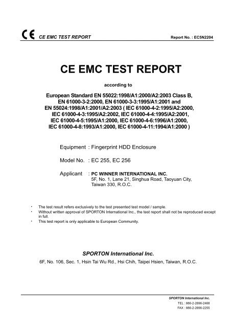
<strong>CE</strong> <strong>EMC</strong> <strong>TEST</strong> <strong>REPORT</strong><br />
Report No. : EC5N2204<br />
<strong>CE</strong> <strong>EMC</strong> <strong>TEST</strong> <strong>REPORT</strong><br />
according to<br />
European Standard EN 55022:1998/A1:2000/A2:2003 Class B,<br />
EN 61000-3-2:2000, EN 61000-3-3:1995/A1:2001 and<br />
EN 55024:1998/A1:2001/A2:2003 ( IEC 61000-4-2:1995/A2:2000,<br />
IEC 61000-4-3:1995/A2:2002, IEC 61000-4-4:1995/A2:2001,<br />
IEC 61000-4-5:1995/A1:2000, IEC 61000-4-6:1996/A1:2000,<br />
IEC 61000-4-8:1993/A1:2000, IEC 61000-4-11:1994/A1:2000 )<br />
Equipment : Fingerprint HDD Enclosure<br />
Model No. : EC 255, EC 256<br />
Applicant<br />
: PC WINNER INTERNATIONAL INC.<br />
5F, No. 1, Lane 21, Singhua Road, Taoyuan City,<br />
Taiwan 330, R.O.C.<br />
• The test result refers exclusively to the test presented test model / sample.<br />
• Without written approval of SPORTON International Inc., the test report shall not be reproduced except<br />
in full.<br />
• This test report is only applicable to European Community.<br />
SPORTON International Inc.<br />
6F, No. 106, Sec. 1, Hsin Tai Wu Rd., Hsi Chih, Taipei Hsien, Taiwan, R.O.C.<br />
SPORTON International Inc.<br />
TEL : 886-2-2696-2468<br />
FAX : 886-2-2696-2255
<strong>CE</strong> <strong>EMC</strong> <strong>TEST</strong> <strong>REPORT</strong><br />
Report No. : EC5N2204<br />
Table of Contents<br />
History of this test report...................................................................................................................................iii<br />
<strong>CE</strong>RTIFICATE OF COMPLIAN<strong>CE</strong>........................................................................................................................1<br />
1. General Description of Equipment under Test.............................................................................................2<br />
1.1 Applicant..........................................................................................................................................................................................2<br />
1.2 Manufacturer ...................................................................................................................................................................................2<br />
1.3 Basic Description of Equipment under Test ....................................................................................................................................2<br />
1.4 Feature of Equipment under Test ...................................................................................................................................................2<br />
2. Test Configuration of Equipment under Test ...............................................................................................3<br />
2.1 Test Manner ....................................................................................................................................................................................3<br />
2.2 Description of Test System .............................................................................................................................................................3<br />
3. Test Software ...................................................................................................................................................6<br />
4. General Information of Test............................................................................................................................7<br />
4.1 Test Facility .....................................................................................................................................................................................7<br />
4.2 Test Voltage ....................................................................................................................................................................................7<br />
4.3 Standard for Methods of Measurement...........................................................................................................................................7<br />
4.4 Test in Compliance with ..................................................................................................................................................................7<br />
4.5 Frequency Range Investigated .......................................................................................................................................................7<br />
4.6 Test Distance ..................................................................................................................................................................................7<br />
5. Test of Conducted Powerline .........................................................................................................................8<br />
5.1 Description of Major Test Instruments ............................................................................................................................................8<br />
5.2 Test Procedures..............................................................................................................................................................................9<br />
5.3 Typical Test Setup Layout of Conducted Powerline .....................................................................................................................10<br />
5.4 Test Result of AC Powerline Conducted Emission .......................................................................................................................11<br />
5.5 Photographs of Conducted Powerline Test Configuration ............................................................................................................13<br />
6. Test of Radiated Emission............................................................................................................................14<br />
6.1 Description of Major Test Instruments ..........................................................................................................................................14<br />
6.2 Test Procedures............................................................................................................................................................................15<br />
6.3 Typical Test Setup Layout of Radiated Emission..........................................................................................................................16<br />
6.4 Test Result of Radiated Emission .................................................................................................................................................17<br />
6.5 Photographs of Radiated Emission Test Configuration ................................................................................................................21<br />
7. Harmonics Test..............................................................................................................................................22<br />
8. Voltage Fluctuations Test.............................................................................................................................23<br />
8.1 Standard........................................................................................................................................................................................23<br />
8.2 Test Procedure..............................................................................................................................................................................23<br />
8.3 Test Equipment Settings ...............................................................................................................................................................23<br />
8.4 Test Setup.....................................................................................................................................................................................23<br />
8.5 Test Result Of Voltage Fluctuation And Flicker Test ....................................................................................................................24<br />
8.6 Photographs Of Voltage Fluctuation And Flicker Test ..................................................................................................................25<br />
9. Electrostatic Discharge Immunity Test (ESD) ............................................................................................26<br />
9.1 Test setup......................................................................................................................................................................................26<br />
9.2 Test Setup for Tests Performed in Laboratory ..............................................................................................................................27<br />
9.3 ESD Test Procedure .....................................................................................................................................................................28<br />
9.4 Test Severity Levels......................................................................................................................................................................29<br />
9.5 Test Points ....................................................................................................................................................................................30<br />
9.6 Photographs of Electrostatic Discharge Immunity Test ................................................................................................................31<br />
SPORTON International Inc. Page Number : i<br />
TEL : 886-2-2696-2468 Issued Date : Dec. 13, 2005<br />
FAX : 886-2-2696-2255
<strong>CE</strong> <strong>EMC</strong> <strong>TEST</strong> <strong>REPORT</strong><br />
Report No. : EC5N2204<br />
10. Radio Frequency Electromagnetic Field Immunity Test (RS).................................................................32<br />
10.1 Test setup......................................................................................................................................................................................32<br />
10.2 Test Procedure..............................................................................................................................................................................33<br />
10.3 Test Severity Levels......................................................................................................................................................................33<br />
10.4 Photographs of Radio Frequency Electromagnetic Field Immunity Test ......................................................................................34<br />
11. Electrical Fast Transient/Burst Immunity Test (EFT/BURST) .................................................................35<br />
11.1 Test setup......................................................................................................................................................................................35<br />
11.2 Test on Power Line .......................................................................................................................................................................36<br />
11.3 Test on Communication Lines.......................................................................................................................................................36<br />
11.4 Test Procedure..............................................................................................................................................................................36<br />
11.5 Test Severity Levels......................................................................................................................................................................37<br />
11.6 Photographs of Electrical Fast Transient/BURST Immunity Test .................................................................................................38<br />
12. SURGE IMMUNITY <strong>TEST</strong>.............................................................................................................................39<br />
12.1 <strong>TEST</strong> RECORD.............................................................................................................................................................................39<br />
12.2 <strong>TEST</strong> LEVEL.................................................................................................................................................................................40<br />
12.3 <strong>TEST</strong> PRO<strong>CE</strong>DURE .....................................................................................................................................................................40<br />
12.4 OPERATING CONDITION............................................................................................................................................................41<br />
12.5 Photographs of SURGE IMMUNITY <strong>TEST</strong> ...................................................................................................................................42<br />
13. CONDUCTED DISTURBAN<strong>CE</strong>S INDU<strong>CE</strong>D BY RADIO-FREQUENCY FIELD IMMUNITY <strong>TEST</strong> ( CS )...43<br />
13.1 <strong>TEST</strong> LEVEL.................................................................................................................................................................................43<br />
13.2 OPERATING CONDITION............................................................................................................................................................43<br />
13.3 <strong>TEST</strong> PRO<strong>CE</strong>DURE .....................................................................................................................................................................44<br />
13.4 Photographs of Conducted Disturbanced Induced By Radio-Frequency Field Immunity Test .....................................................45<br />
14. Power Frequency Magnetic Field immunity tests....................................................................................46<br />
14.1 <strong>TEST</strong> RECORD.............................................................................................................................................................................46<br />
14.2 <strong>TEST</strong> SETUP ................................................................................................................................................................................46<br />
14.3 Photographs of Power Frequency Magnetic Field immunity tests ................................................................................................47<br />
15. VOLTAGE DIPS AND VOLTAGE INTERRUPTIONS IMMUNITY <strong>TEST</strong>S ..................................................48<br />
15.1 <strong>TEST</strong> RECORD OF VOLTAGE INTERRUPTION ........................................................................................................................48<br />
15.2 <strong>TEST</strong> RECORD OF VOLTAGE DIPS ...........................................................................................................................................48<br />
15.3 <strong>TEST</strong>ING REQUIREMENT AND PRO<strong>CE</strong>DURE ..........................................................................................................................49<br />
15.4 <strong>TEST</strong> CONDITIONS......................................................................................................................................................................49<br />
15.5 OPERATING CONDITION............................................................................................................................................................49<br />
15.6 Photographs of VOLTAGE DIPS AND VOLTAGE IMMUNITY <strong>TEST</strong>S ........................................................................................50<br />
16. List of Measuring Equipment Used ...........................................................................................................51<br />
17. Notice for Class A Product.........................................................................................................................53<br />
18. Declaration of Conformity and the <strong>CE</strong> Mark.............................................................................................54<br />
Appendix A. Photographs of EUT........................................................................................................ A1 ~ A31<br />
SPORTON International Inc. Page Number : ii<br />
TEL : 886-2-2696-2468 Issued Date : Dec. 13, 2005<br />
FAX : 886-2-2696-2255
<strong>CE</strong> <strong>EMC</strong> <strong>TEST</strong> <strong>REPORT</strong><br />
Report No. : EC5N2204<br />
History of this test report<br />
Original Report Issue Date: Dec. 13, 2005<br />
■ No additional attachment.<br />
□ Additional attachment were issued as following record:<br />
Attachment No. Issue Date Description<br />
SPORTON International Inc. Page Number : iii<br />
TEL : 886-2-2696-2468 Issued Date : Dec. 13, 2005<br />
FAX : 886-2-2696-2255
<strong>CE</strong> <strong>EMC</strong> <strong>TEST</strong> <strong>REPORT</strong><br />
Report No. : EC5N2204<br />
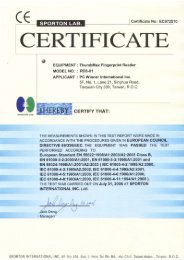
Certificate No. : EC5N2204<br />
<strong>CE</strong>RTIFICATE OF COMPLIAN<strong>CE</strong><br />
according to<br />
European Standard EN 55022:1998/A1:2000/A2:2003 Class B,<br />
EN 61000-3-2:2000, EN 61000-3-3:1995/A1:2001 and<br />
EN 55024:1998/A1:2001/A2:2003 ( IEC 61000-4-2:1995/A2:2000,<br />
IEC 61000-4-3:1995/A2:2002, IEC 61000-4-4:1995/A2:2001,<br />
IEC 61000-4-5:1995/A1:2000, IEC 61000-4-6:1996/A1:2000,<br />
IEC 61000-4-8:1993/A1:2000, IEC 61000-4-11:1994/A1:2000 )<br />
Equipment : Fingerprint HDD Enclosure<br />
Model No. : EC 255, EC 256<br />
Applicant<br />
: PC WINNER INTERNATIONAL INC.<br />
5F, No. 1, Lane 21, Singhua Road, Taoyuan City,<br />
Taiwan 330, R.O.C.<br />
I HEREBY <strong>CE</strong>RTIFY THAT :<br />
The measurements shown in this test report were made in accordance with the procedures given in<br />
EUROPEAN COUNCIL DIRECTIVE 89/336/EEC. The equipment was passed the test performed according<br />
to European Standard EN 55022:1998/A1:2000/A2:2003 Class B, EN 61000-3-2:2000,<br />
EN 61000-3-3:1995/A1:2001 and EN 55024:1998/A1:2001/A2:2003 ( IEC 61000-4-2:1995/A2:2000,<br />
IEC 61000-4-3:1995/A2:2002, IEC 61000-4-4:1995/A2:2001, IEC 61000-4-5:1995/A1:2000,<br />
IEC 61000-4-6:1996/A1:2000, IEC 61000-4-8:1993/A1:2000, IEC 61000-4-11:1994/A1:2000 ). The test was<br />
carried out on Dec. 08, 2005 at SPORTON International Inc.<br />
Jones Chan<br />
Supervisor<br />
SPORTON International Inc.<br />
6F, No. 106, Sec. 1, Hsin Tai Wu Rd., Hsi Chih, Taipei Hsien, Taiwan, R.O.C.<br />
SPORTON International Inc. Page Number : 1 of 54<br />
TEL : 886-2-2696-2468 Issued Date : Dec. 13, 2005<br />
FAX : 886-2-2696-2255
<strong>CE</strong> <strong>EMC</strong> <strong>TEST</strong> <strong>REPORT</strong><br />
Report No. : EC5N2204<br />
1. General Description of Equipment under Test<br />
1.1 Applicant<br />
PC WINNER INTERNATIONAL INC.<br />
5F, No. 1, Lane 21, Singhua Road, Taoyuan City, Taiwan 330, R.O.C.<br />
1.2 Manufacturer<br />
Same as 1.1<br />
1.3 Basic Description of Equipment under Test<br />
Equipment<br />
: Fingerprint HDD Enclosure<br />
Model No. : EC 255, EC 256<br />
Trade Name : PC Winner. ThumbMax<br />
USB Cable : Braided-Shielded, 1.0m<br />
Power Supply Type : Switching<br />
AC Power Cord : Non-Shielded, 1.8m, 3 pin<br />
1.4 Feature of Equipment under Test<br />
Interface: USB 2.0<br />
Adapter: DVE / DSA-0101F-05<br />
Input: 100-240V, 50/60Hz 0.3A<br />
Output: 5V/ 2A<br />
SPORTON International Inc. Page Number : 2 of 54<br />
TEL : 886-2-2696-2468 Issued Date : Dec. 13, 2005<br />
FAX : 886-2-2696-2255
<strong>CE</strong> <strong>EMC</strong> <strong>TEST</strong> <strong>REPORT</strong><br />
Report No. : EC5N2204<br />
2. Test Configuration of Equipment under Test<br />
2.1 Test Manner<br />
a. During testing, the interface cables and equipment positions were varied according to European<br />
Standard EN 55022.<br />
b. The complete test system <strong>inc</strong>luded COMPAQ PC, VIEWSONIC LCD Monitor, COMPAQ PS/2<br />
Keyboard, COMPAQ PS/2 Mouse, EPSON Printer, A<strong>CE</strong>EX Modem, HITACHI HDD and EUT for EMI<br />
test.<br />
c. The complete test system <strong>inc</strong>luded DELL Notebook, HITACHI HDD and EUT for EMS test.<br />
d. For Conducted test, the following mode was final tested:<br />
Mode 1. EC 255<br />
e. For Radiated test, the following modes were pretested:<br />
Mode 1. EC 255<br />
Mode 2. EC 256<br />
cause “ Mode 1” generated the worst test result, it was reported as final data<br />
f. Frequency range investigated: conduction 150 KHz to 30 MHz, radiation 30 MHz to 1000MHz.<br />
2.2 Description of Test System<br />
< EMI ><br />
Support Unit 1. -- LCD Monitor (VIEWSONIC)<br />
FCC ID<br />
: N/A<br />
Model No.<br />
: VLCDS6104-3W<br />
Power Supply Type : Switching<br />
Power Cord<br />
: Non-Shielded<br />
Serial No.<br />
: SP0013<br />
Data Cable : D-Shielded, 360 degree via metal backshells, 1.8m<br />
Remark<br />
: This support device was tested to comply with FCC standards<br />
and authorized under a declaration of conformity.<br />
Support Unit 2. -- Printer (EPSON)<br />
FCC ID<br />
: N/A<br />
Model No.<br />
: EPSON STYLUS C61<br />
Power Supply Type : Linear<br />
Power Cord<br />
: Non-Shielded<br />
Serial No.<br />
: SP0019<br />
Data Cable : Shielded, 360 degree via metal backshells, 1.8m<br />
Remark<br />
: This support device was tested to comply with FCC standards and<br />
authorized under a declaration of conformity.<br />
SPORTON International Inc. Page Number : 3 of 54<br />
TEL : 886-2-2696-2468 Issued Date : Dec. 13, 2005<br />
FAX : 886-2-2696-2255
<strong>CE</strong> <strong>EMC</strong> <strong>TEST</strong> <strong>REPORT</strong><br />
Report No. : EC5N2204<br />
Support Unit 3. -- Modem (A<strong>CE</strong>EX)<br />
FCC ID<br />
: IFAXDM1414<br />
Model No.<br />
: DM1414<br />
Power Supply Type : Linear<br />
Power Cord<br />
: Non-Shielded<br />
Serial No.<br />
: SP0020<br />
Data Cable : Shielded, 360 degree via metal backshells, 1.8m<br />
Support Unit 4. -- PS/2 Keyboard (COMPAQ)<br />
FCC ID<br />
: N/A<br />
Model No.<br />
: 6511-VA<br />
Serial No.<br />
: SP0017<br />
Data Cable : AL-F-Shielded, 1.8m<br />
Remark<br />
: This support device was tested to comply with FCC standards<br />
and authorized under a declaration of conformity.<br />
Support Unit 5. -- PS/2 Mouse (COMPAQ)<br />
FCC ID<br />
: N/A<br />
Model No.<br />
: M-S69<br />
Serial No.<br />
: SP0015<br />
Data Cable : AL-F-Shielded, 1.8m<br />
Remark<br />
: This support device was tested to comply with FCC standards<br />
and authorized under a declaration of conformity.<br />
Support Unit 6. -- Personal Computer (COMPAQ)<br />
FCC ID<br />
: N/A<br />
Model No.<br />
: Evo D380MX<br />
Power Supply Type : Switching<br />
Serial No.<br />
: SP0006<br />
Remark<br />
: This support device was tested to comply with FCC standards<br />
and authorized under a declaration of conformity.<br />
Support Unit 7. -- HDD (HITACHI)<br />
Model No.<br />
: HTS548030M9AT00 (30G)<br />
SPORTON International Inc. Page Number : 4 of 54<br />
TEL : 886-2-2696-2468 Issued Date : Dec. 13, 2005<br />
FAX : 886-2-2696-2255
<strong>CE</strong> <strong>EMC</strong> <strong>TEST</strong> <strong>REPORT</strong><br />
Report No. : EC5N2204<br />
< EMS ><br />
Support Unit 1. -- Notebook (DELL)<br />
FCC ID<br />
Model No.<br />
Power Cord<br />
Serial No.<br />
Remark<br />
: N/A<br />
: PP10S<br />
: Non-Shielded<br />
: SP0033<br />
: This support device was tested to comply with FCC standards and<br />
authorized under a declaration of conformity.<br />
Support Unit 2. -- HDD (HITACHI)<br />
Model No.<br />
: HTS548030M9AT00 (30G)<br />
SPORTON International Inc. Page Number : 5 of 54<br />
TEL : 886-2-2696-2468 Issued Date : Dec. 13, 2005<br />
FAX : 886-2-2696-2255
<strong>CE</strong> <strong>EMC</strong> <strong>TEST</strong> <strong>REPORT</strong><br />
Report No. : EC5N2204<br />
3. Test Software<br />
< EMI ><br />
An executive program, <strong>EMC</strong><strong>TEST</strong>.EXE under WIN XP, which generate a complete line of continuously<br />
repeating “ H “ pattern was used as the test software.<br />
The program was executed as follows :<br />
a. Turn on the power of all equipment.<br />
b. The PC reads the test program from the hard disk drive and runs it.<br />
c. The PC sends " H " messages to the monitor, and the monitor displays " H " patterns on the screen.<br />
d. The PC sends " H " messages to the printer, then the printer prints them on the paper.<br />
e. The PC sends " H " messages to the modem.<br />
f. The PC sends " H " messages to the internal Hard Disk, and the Hard Disk reads and writes the message.<br />
g. Repeat the steps from c to f.<br />
h. At the same time, “WINTHRAX.EXE” to read data from EUT.<br />
< EMS ><br />
An executive program, <strong>EMC</strong><strong>TEST</strong>.EXE under WIN XP, which generate a complete line of continuously<br />
repeating “ H “ pattern was used as the test software.<br />
The program was executed as follows :<br />
a. Turn on the power of all equipment.<br />
b. The Notebook reads the test program from the hard disk drive and runs it.<br />
c. The Notebook sends “ H “ messages to the monitor, and the monitor displays “ H “ patterns on the screen.<br />
d. The Notebook sends “ H ” messages to the internal Hard Disk, and the Hard Disk reads and writes the<br />
message.<br />
e. Repeat the steps from c to d.<br />
f. At the same time, “WINTHRAX.EXE” to read data from EUT.<br />
SPORTON International Inc. Page Number : 6 of 54<br />
TEL : 886-2-2696-2468 Issued Date : Dec. 13, 2005<br />
FAX : 886-2-2696-2255
<strong>CE</strong> <strong>EMC</strong> <strong>TEST</strong> <strong>REPORT</strong><br />
Report No. : EC5N2204<br />
4. General Information of Test<br />
4.1 Test Facility<br />
<br />
Test Site Location : No. 30-2, Lin 6, Diing-Fwu Tsuen, Lin-Kou-Hsiang,<br />
Taipei Hsien, Taiwan, R.O.C.<br />
TEL : 886-2-2601-1640<br />
FAX : 886-2-2601-1695<br />
Test Site No. : CO02-LK, OS06-LK<br />
<br />
Test Site Location : No. 52, Hwa Ya 1St Road, Hwa Ya Technology Park,<br />
Kwei-Shan Hsiang, TaoYuan Hsien, Taiwan, R.O.C.<br />
TEL : 886-3-3273456<br />
FAX : 886-3-3180055<br />
4.2 Test Voltage<br />
230V/50Hz<br />
4.3 Standard for Methods of Measurement<br />
EMI Test (Conduction and Radiation ) : European Standard EN55022 Class B<br />
Harmonics Test<br />
: European Standard EN61000-3-2.<br />
Voltage Fluctuations Test<br />
: European Standard EN61000-3-3.<br />
EMS Test<br />
: European Standard EN55024.<br />
(ESD: IEC61000-4-2, RS: IEC61000-4-3, EFT: IEC61000-4-4, SURGE: IEC61000-4-5,<br />
CS: IEC61000-4-6, Power Frequency Magnetic Field: IEC61000-4-8, DIPS: IEC61000-4-11)<br />
4.4 Test in Compliance with<br />
EMI Test (Conduction and Radiation ) : European Standard EN55022 Class B<br />
Harmonics Test<br />
: European Standard EN61000-3-2.<br />
Voltage Fluctuations Test<br />
: European Standard EN61000-3-3.<br />
EMS Test<br />
: European Standard EN55024.<br />
(ESD: IEC61000-4-2, RS: IEC61000-4-3, EFT: IEC61000-4-4, SURGE: IEC61000-4-5,<br />
CS: IEC61000-4-6, Power Frequency Magnetic Field: IEC61000-4-8, DIPS: IEC61000-4-11)<br />
4.5 Frequency Range Investigated<br />
a. Conducted emission test: from 150 kHz to 30 MHz<br />
b. Radiated emission test: from 30 MHz to 1,000 MHz<br />
c. Radio frequency electromagnetic field immunity test : 80-1000 MHz.<br />
4.6 Test Distance<br />
The test distance of radiated emission test from antenna to EUT is 10 M.<br />
The test distance of radio frequency electromagnetic field immunity test from antenna to EUT is 3 M.<br />
SPORTON International Inc. Page Number : 7 of 54<br />
TEL : 886-2-2696-2468 Issued Date : Dec. 13, 2005<br />
FAX : 886-2-2696-2255
<strong>CE</strong> <strong>EMC</strong> <strong>TEST</strong> <strong>REPORT</strong><br />
Report No. : EC5N2204<br />
5. Test of Conducted Powerline<br />
Conducted Emissions were measured from 150 kHz to 30 MHz with a bandwidth of 9 kHz on the power and<br />
return leads of the EUT according to the methods defined in European Standard EN55022 Clause 9. The<br />
EUT was placed on a nonmetallic stand in a shielded room 0.8 meters above the ground plane as shown in<br />
section 5.3. The interface cables and equipment positioning were varied within limits of reasonable<br />
applications to determine the position producing maximum conducted emissions.<br />
5.1 Description of Major Test Instruments<br />
• Test Receiver ( R&S ESCS 30 )<br />
Attenuation<br />
10 dB<br />
Start Frequency<br />
0.15 MHz<br />
Stop Frequency<br />
30 MHz<br />
IF Bandwidth<br />
9 KHz<br />
SPORTON International Inc. Page Number : 8 of 54<br />
TEL : 886-2-2696-2468 Issued Date : Dec. 13, 2005<br />
FAX : 886-2-2696-2255
<strong>CE</strong> <strong>EMC</strong> <strong>TEST</strong> <strong>REPORT</strong><br />
Report No. : EC5N2204<br />
5.2 Test Procedures<br />
a. The EUT was placed on a desk 0.8 meters height from the metal ground plane and 0.4 meter from the<br />
conducting wall of the shielding room and it was kept at least 0.8 meters from any other grounded<br />
conducting surface.<br />
b. Connect EUT to the power mains through a line impedance stabilization network (LISN).<br />
c. All the support units are connect to the other LISN.<br />
d. The LISN provides 50 ohm coupling impedance for the measuring instrument.<br />
e. The CISPR states that a 50 ohm , 50 microhenry LISN should be used.<br />
f. Both sides of AC line were checked for maximum conducted interference.<br />
g. The frequency range from 150 kHz to 30 MHz was searched.<br />
h. Set the test-receiver system to Peak Detect Function and Specified Bandwidth with Maximum Hold<br />
Mode.<br />
SPORTON International Inc. Page Number : 9 of 54<br />
TEL : 886-2-2696-2468 Issued Date : Dec. 13, 2005<br />
FAX : 886-2-2696-2255
<strong>CE</strong> <strong>EMC</strong> <strong>TEST</strong> <strong>REPORT</strong><br />
Report No. : EC5N2204<br />
5.3 Typical Test Setup Layout of Conducted Powerline<br />
10 cm<br />
80 cm to the ground plane<br />
L.I.S.N.<br />
L.I.S.N.<br />
SPORTON International Inc. Page Number : 10 of 54<br />
TEL : 886-2-2696-2468 Issued Date : Dec. 13, 2005<br />
FAX : 886-2-2696-2255
<strong>CE</strong> <strong>EMC</strong> <strong>TEST</strong> <strong>REPORT</strong><br />
Report No. : EC5N2204<br />
5.4 Test Result of AC Powerline Conducted Emission<br />
• Frequency Range of Test : from 0.15 MHz to 30 MHz<br />
• Temperature : 17 ℃<br />
• Relative Humidity : 58 %<br />
• Corrected Reading (dBuV) = LISN Factor + Cable Loss + Read Level = Level<br />
■ The test was passed at the minimum margin that marked by a frame in the following table<br />
SPORTON International Inc. Page Number : 11 of 54<br />
TEL : 886-2-2696-2468 Issued Date : Dec. 13, 2005<br />
FAX : 886-2-2696-2255
<strong>CE</strong> <strong>EMC</strong> <strong>TEST</strong> <strong>REPORT</strong><br />
Report No. : EC5N2204<br />
Test Engineer :<br />
Sam Chang<br />
SPORTON International Inc. Page Number : 12 of 54<br />
TEL : 886-2-2696-2468 Issued Date : Dec. 13, 2005<br />
FAX : 886-2-2696-2255
<strong>CE</strong> <strong>EMC</strong> <strong>TEST</strong> <strong>REPORT</strong><br />
Report No. : EC5N2204<br />
5.5 Photographs of Conducted Powerline Test Configuration<br />
• The photographs show the configuration that generates the maximum emission.<br />
FRONT VIEW<br />
REAR VIEW<br />
SPORTON International Inc. Page Number : 13 of 54<br />
TEL : 886-2-2696-2468 Issued Date : Dec. 13, 2005<br />
FAX : 886-2-2696-2255
<strong>CE</strong> <strong>EMC</strong> <strong>TEST</strong> <strong>REPORT</strong><br />
Report No. : EC5N2204<br />
6. Test of Radiated Emission<br />
Radiated emissions from 30 MHz to 1000 MHz were measured with a bandwidth of 120 kHz according to the<br />
methods defines in European Standard EN55022, Clause 10. The EUT was placed on a nonmetallic stand,<br />
0.8 meter above the ground plane, as shown in section 6.3. The interface cables and equipment positions<br />
were varied within limits of reasonable applications to determine the positions producing maximum radiated<br />
emissions.<br />
6.1 Description of Major Test Instruments<br />
• Spectrum Analyzer (R&S FSP7 )<br />
Attenuation<br />
10 dB<br />
Start Frequency<br />
30 MHz<br />
Stop Frequency<br />
1000 MHz<br />
Resolution Bandwidth<br />
120 KHz<br />
Signal Input<br />
9 KHz to 7 GHz<br />
• Amplifier (HP 8447D)<br />
RF Gain<br />
25 dB<br />
Signal Input<br />
100KHz -1.3GHz<br />
• Test Receiver ( R&S ESCS 30 )<br />
Resolution Bandwidth<br />
120 KHz<br />
Frequency Band<br />
9 K – 2.75 GHz<br />
Quasi-Peak Detector<br />
ON for Quasi-Peak Mode<br />
OFF for Peak Mode<br />
SPORTON International Inc. Page Number : 14 of 54<br />
TEL : 886-2-2696-2468 Issued Date : Dec. 13, 2005<br />
FAX : 886-2-2696-2255
<strong>CE</strong> <strong>EMC</strong> <strong>TEST</strong> <strong>REPORT</strong><br />
Report No. : EC5N2204<br />
6.2 Test Procedures<br />
a. The EUT was placed on a rotatable table top 0.8 meter above ground.<br />
b. The EUT was set 10 meters from the interference-receiving antenna which was mounted on the top of<br />
a variable height antenna tower.<br />
c. The table was rotated 360 degrees to determine the position of the highest radiation.<br />
d. The antenna is a half wave dipole and its height is varied between one meter and four meters above<br />
ground to find the maximum value of the field strength both horizontal polarization and vertical<br />
polarization of the antenna are set to make the measurement.<br />
e. For each suspected emission the EUT was arranged to its worst case and then tune the antenna tower<br />
(from 1 M to 4 M) and turn table (from 0 degree to 360 degrees) to find the maximum reading.<br />
f. Set the test-receiver system to Peak Detect Function and specified bandwidth with Maximum Hold<br />
Mode.<br />
g. If the emission level of the EUT in peak mode was 3 dB lower than the limit specified, then testing will<br />
be stopped and peak values of EUT will be reported, otherwise, the emissions which do not have 3 dB<br />
margin will be repeated one by one using the quasi-peak method and reported.<br />
SPORTON International Inc. Page Number : 15 of 54<br />
TEL : 886-2-2696-2468 Issued Date : Dec. 13, 2005<br />
FAX : 886-2-2696-2255
<strong>CE</strong> <strong>EMC</strong> <strong>TEST</strong> <strong>REPORT</strong><br />
Report No. : EC5N2204<br />
6.3 Typical Test Setup Layout of Radiated Emission<br />
Antenna<br />
Equipment under Test<br />
Test distance<br />
0.8 M<br />
Ground Plane<br />
TurnTable<br />
Receiver<br />
SPORTON International Inc. Page Number : 16 of 54<br />
TEL : 886-2-2696-2468 Issued Date : Dec. 13, 2005<br />
FAX : 886-2-2696-2255
<strong>CE</strong> <strong>EMC</strong> <strong>TEST</strong> <strong>REPORT</strong><br />
Report No. : EC5N2204<br />
6.4 Test Result of Radiated Emission<br />
• Frequency Range of Test : from 30 MHz to 1000 MHz<br />
• Test Distance : 10m<br />
• Temperature : 13 ℃<br />
• Relative Humidity : 69 %<br />
• Emission level (dBuV/m) = 20 log Emission level (uV/m)<br />
• Corrected Reading: Antenna Factor + Cable Loss + Read Level - Preamp Factor = Level<br />
■The test was passed at the minimum margin that marked by the frame in the following test record<br />
SPORTON International Inc. Page Number : 17 of 54<br />
TEL : 886-2-2696-2468 Issued Date : Dec. 13, 2005<br />
FAX : 886-2-2696-2255
<strong>CE</strong> <strong>EMC</strong> <strong>TEST</strong> <strong>REPORT</strong><br />
Report No. : EC5N2204<br />
SPORTON International Inc. Page Number : 18 of 54<br />
TEL : 886-2-2696-2468 Issued Date : Dec. 13, 2005<br />
FAX : 886-2-2696-2255
<strong>CE</strong> <strong>EMC</strong> <strong>TEST</strong> <strong>REPORT</strong><br />
Report No. : EC5N2204<br />
SPORTON International Inc. Page Number : 19 of 54<br />
TEL : 886-2-2696-2468 Issued Date : Dec. 13, 2005<br />
FAX : 886-2-2696-2255
<strong>CE</strong> <strong>EMC</strong> <strong>TEST</strong> <strong>REPORT</strong><br />
Report No. : EC5N2204<br />
Test Engineer :<br />
Fred Yu<br />
SPORTON International Inc. Page Number : 20 of 54<br />
TEL : 886-2-2696-2468 Issued Date : Dec. 13, 2005<br />
FAX : 886-2-2696-2255
<strong>CE</strong> <strong>EMC</strong> <strong>TEST</strong> <strong>REPORT</strong><br />
Report No. : EC5N2204<br />
6.5 Photographs of Radiated Emission Test Configuration<br />
• The photographs show the configuration that generates the maximum emission.<br />
FRONT VIEW<br />
REAR VIEW<br />
SPORTON International Inc. Page Number : 21 of 54<br />
TEL : 886-2-2696-2468 Issued Date : Dec. 13, 2005<br />
FAX : 886-2-2696-2255
<strong>CE</strong> <strong>EMC</strong> <strong>TEST</strong> <strong>REPORT</strong><br />
Report No. : EC5N2204<br />
7. Harmonics Test<br />
As specified on clause 7 and figure Z1 of EN 61000-3-2:2000, the limits are not specified for equipment with<br />
a rated power of 75W or less.<br />
The EUT meets the above condition, so it conforms to EN 61000-3-2.<br />
SPORTON International Inc. Page Number : 22 of 54<br />
TEL : 886-2-2696-2468 Issued Date : Dec. 13, 2005<br />
FAX : 886-2-2696-2255
<strong>CE</strong> <strong>EMC</strong> <strong>TEST</strong> <strong>REPORT</strong><br />
Report No. : EC5N2204<br />
8. Voltage Fluctuations Test<br />
8.1 Standard<br />
• Standard : EN61000-3-3:1995/A1:2001<br />
8.2 Test Procedure<br />
The equipment shall be tested under the conditions of Clause 5.<br />
The total impedance of the test circuit, excluding the appliance under test, but <strong>inc</strong>luding the internal<br />
impedance of the supply source, shall be equal to the reference impedance. The stability and tolerance of<br />
the reference impedance shall be adequate to ensure that the overall accuracy of ±8% is achieved during<br />
the whole assessment procedure.<br />
8.3 Test Equipment Settings<br />
• Line Voltage : 230 V<br />
• Line Frequency : 50 Hz<br />
• Measurement Delay : 10.0 seconds<br />
• Pst Integration Time : 10 minutes<br />
• Pst Integration Periods : 1<br />
• Test Duration : 00:10:00 minutes<br />
8.4 Test Setup<br />
SPORTON International Inc. Page Number : 23 of 54<br />
TEL : 886-2-2696-2468 Issued Date : Dec. 13, 2005<br />
FAX : 886-2-2696-2255
<strong>CE</strong> <strong>EMC</strong> <strong>TEST</strong> <strong>REPORT</strong><br />
Report No. : EC5N2204<br />
8.5 Test Result Of Voltage Fluctuation And Flicker Test<br />
• FINAL <strong>TEST</strong> RESULT : PASS<br />
• Temperature : 24 ℃<br />
• Relative Humidity : 52 % RH<br />
• Atmospheric pressure : 99 kPa<br />
• Test Date : Dec. 08, 2005<br />
Urms = 230.1V Freq = 50.000 Range: 0.5 A<br />
Irms = 0.064A Ipk = 0.316A cf = 4.924<br />
P = 5.951W Pap = 14.78VA pf = 0.403<br />
Test - Time : 1 x 10min = 10min ( 100 %)<br />
LIN (Line Impedance Network) : SLIN 0.24ohm +j0.15ohm N:0.16ohm +j0.10ohm<br />
Limits : Plt : 0.65 Pst : 1.00<br />
dmax : 4.00 % dc : 3.30 %<br />
dtLim: 3.30 % dt>Lim: 500ms<br />
Test completed, Result: PASSED<br />
Plt = 0.072<br />
Pst P50s P10s P3s P1s P0.1s dmax dc dt>Lim<br />
1 0.072 0.010 0.010 0.010 0.010 0.010 0.000 0.010 0.000<br />
Test Engineer :<br />
Cat Lin<br />
SPORTON International Inc. Page Number : 24 of 54<br />
TEL : 886-2-2696-2468 Issued Date : Dec. 13, 2005<br />
FAX : 886-2-2696-2255
<strong>CE</strong> <strong>EMC</strong> <strong>TEST</strong> <strong>REPORT</strong><br />
Report No. : EC5N2204<br />
8.6 Photographs Of Voltage Fluctuation And Flicker Test<br />
FRONT VIEW<br />
REAR VIEW<br />
SPORTON International Inc. Page Number : 25 of 54<br />
TEL : 886-2-2696-2468 Issued Date : Dec. 13, 2005<br />
FAX : 886-2-2696-2255
<strong>CE</strong> <strong>EMC</strong> <strong>TEST</strong> <strong>REPORT</strong><br />
Report No. : EC5N2204<br />
9. Electrostatic Discharge Immunity Test (ESD)<br />
• FINAL <strong>TEST</strong> RESULT : PASS<br />
• Pass Performance Criteria : A<br />
• Required performance criteria : B<br />
• Basic Standard : IEC 61000-4-2:1995/A2:2000<br />
• Product Standard : EN55024:1998/A1:2001/A2:2003<br />
• Level : 3 for air discharge,<br />
2 for contact discharge<br />
• Tested voltage : ±2 / ±4 / ±8 KV for air discharge,<br />
±2 / ±4 KV for contact discharge<br />
• Temperature : 24 ℃<br />
• Relative Humidity : 52 %<br />
• Atmospheric pressure : 99 kPa<br />
• Observation : Dec. 08, 2005<br />
9.1 Test setup<br />
The test setup consists of the test generator, EUT and auxiliary instrumentation necessary to perform<br />
DIRECT and INDIRECT application of discharges to the EUT as applicable, in the follow manner :<br />
a. CONTACT DISCHARGE to the conductive surfaces and to coupling plane;<br />
b. AIR DISCHARGE at insulating surfaces.<br />
The preferred test method is that of type tests performed in laboratories and the only accepted method of<br />
demonstrating conformance with this standard. The EUT was arranged as closely as possible to<br />
arrangement in final installed conditions.<br />
SPORTON International Inc. Page Number : 26 of 54<br />
TEL : 886-2-2696-2468 Issued Date : Dec. 13, 2005<br />
FAX : 886-2-2696-2255
<strong>CE</strong> <strong>EMC</strong> <strong>TEST</strong> <strong>REPORT</strong><br />
Report No. : EC5N2204<br />
9.2 Test Setup for Tests Performed in Laboratory<br />
A ground reference plane was provided on the floor of the test site. It was a metallic sheet (copper or<br />
aluminum) of 0.25 mm, minimum thickness; other metallic may be used but they shall have at least 0.65<br />
mm thickness. In the SPORTON <strong>EMC</strong> LAB., we provided 1 mm thickness aluminum ground reference<br />
plane or 1 mm thickness stainless steel ground reference plane. The minimum size of the ground reference<br />
plane is 1 m x 1 m, the exact size depending on the dimensions of the EUT. It was connected to the<br />
protective grounding system.<br />
The EUT was arranged and connected according to its functional requirements. A distance of 1m minimum<br />
was provided between the EUT and the wall of the lab. and any other metallic structure. In cases where this<br />
length exceeds the length necessary to apply the discharges to the selected points, the excess length shall,<br />
where possible, be placed non-inductively off the ground reference plane and shall not come closer than<br />
0.2m to other conductive parts in the test setup.<br />
Where the EUT is installed on a metal table, the table was connected to the reference plane via a cable<br />
with a 470k ohm resister located at each end, to prevent a build-up of charge. The test setup was consist a<br />
wooden table, 0.8m high, standing on the ground reference plane. A HCP, 1.6 m x 0.8 m, was placed on the<br />
table. The EUT and cables was isolated from the HCP by an insulating support 0.5 mm thick. The VCP size,<br />
0.5 m x 0.5 m.<br />
SPORTON International Inc. Page Number : 27 of 54<br />
TEL : 886-2-2696-2468 Issued Date : Dec. 13, 2005<br />
FAX : 886-2-2696-2255
<strong>CE</strong> <strong>EMC</strong> <strong>TEST</strong> <strong>REPORT</strong><br />
Report No. : EC5N2204<br />
9.3 ESD Test Procedure<br />
a. In the case of air discharge testing the climatic conditions shall be within the following ranges:<br />
- ambient temperature: 15℃ to 35℃;<br />
- relative humidity : 30% to 60%;<br />
- atmospheric pressure : 86 kPa (860 mbar) to 106 kPa (1060 mbar).<br />
b. Test programs and software shall be chosen so as to exercise all normal modes of operation of the EUT.<br />
The use of special exercising software is encouraged, but permitted only where it can be shown that the<br />
EUT is being comprehensively exercised.<br />
c. The test voltage shall be <strong>inc</strong>reased from the minimum to the selected test severity level, in order to<br />
determine any threshold of failure. The final severity level should not exceed the product specification<br />
value in order to avoid damage to the equipment.<br />
d. The test shall be performed with both air discharge and contact discharge. On preselected points at least<br />
10 single discharges (in the most sensitive polarity) shall be applied on air discharge. On preselected<br />
points at least 25 single discharges (in the most sensitive polarity) shall be applied on contact discharge.<br />
e. For the time interval between successive single discharges an initial value of one second is<br />
recommended. Longer intervals may be necessary to determine whether a system failure has occurred.<br />
f. In the case of contact discharges, the tip of the discharge electrode shall touch the EUT before the<br />
discharge switch is operated.<br />
g. In the case of painted surface covering a conducting substrate, the following procedure shall be<br />
adopted :<br />
- If the coating is not declared to be an insulating coating by the equipment manufacturer, then the<br />
pointed tip of the generator shall penetrate the coating so as to make contact with the conducting<br />
substrate.<br />
- Coating declared as insulating by the manufacturer shall only be submitted to the air discharge.<br />
- The contact discharge test shall not be applied to such surfaces.<br />
h. In the case of air discharges, the round discharge tip of the discharge electrode shall be approached as<br />
fast as possible (without causing mechanical damage) to touch the EUT . After each discharge, the ESD<br />
generator (discharge electrode) shall be removed from the EUT. The generator is then retriggered for a<br />
new single discharge. This procedure shall be repeated until the discharges are completed. In the case<br />
of an air discharge test, the discharge switch, which is used for contact discharge, shall be closed.<br />
SPORTON International Inc. Page Number : 28 of 54<br />
TEL : 886-2-2696-2468 Issued Date : Dec. 13, 2005<br />
FAX : 886-2-2696-2255
<strong>CE</strong> <strong>EMC</strong> <strong>TEST</strong> <strong>REPORT</strong><br />
Report No. : EC5N2204<br />
9.4 Test Severity Levels<br />
9.4.1 Contact Discharge<br />
Level<br />
Test Voltage (KV) of Contact discharge<br />
1 ±2<br />
2 ±4<br />
3 ±6<br />
4 ±8<br />
X<br />
Specified<br />
Remark : “X” is an open level.<br />
9.4.2 Air Discharge<br />
Level<br />
Test Voltage (KV) of Air Discharge<br />
1 ±2<br />
2 ±4<br />
3 ±8<br />
4 ±15<br />
X<br />
Specified<br />
Remark : “X” is an open level.<br />
SPORTON International Inc. Page Number : 29 of 54<br />
TEL : 886-2-2696-2468 Issued Date : Dec. 13, 2005<br />
FAX : 886-2-2696-2255
<strong>CE</strong> <strong>EMC</strong> <strong>TEST</strong> <strong>REPORT</strong><br />
Report No. : EC5N2204<br />
9.5 Test Points<br />
9.5.1 Test Result of Air Discharge<br />
Test Point Voltage Tested No.<br />
LED ±2 / ±4 / ±8 KV BY 10<br />
DC input jack ±2 / ±4 / ±8 KV BY 10<br />
USB Port ±2 / ±4 / ±8 KV BY 10<br />
Fingerprint block ±2 / ±4 / ±8 KV BY 10<br />
9.5.2 Result of Contact Discharge<br />
Test Point Voltage Tested No.<br />
HCP (At Front) ±2 / ±4 KV BY 25<br />
HCP (At Left) ±2 / ±4 KV BY 25<br />
HCP (At Right) ±2 / ±4 KV BY 25<br />
HCP (At Rear) ±2 / ±4 KV BY 25<br />
VCP (At Front) ±2 / ±4 KV BY 25<br />
VCP (At Left) ±2 / ±4 KV BY 25<br />
VCP (At Right) ±2 / ±4 KV BY 25<br />
VCP (At Rear) ±2 / ±4 KV BY 25<br />
Case ±2 / ±4 KV BY 25<br />
Screw ±2 / ±4 KV BY 25<br />
Test Engineer :<br />
Cat Lin<br />
SPORTON International Inc. Page Number : 30 of 54<br />
TEL : 886-2-2696-2468 Issued Date : Dec. 13, 2005<br />
FAX : 886-2-2696-2255
<strong>CE</strong> <strong>EMC</strong> <strong>TEST</strong> <strong>REPORT</strong><br />
Report No. : EC5N2204<br />
9.6 Photographs of Electrostatic Discharge Immunity Test<br />
FRONT VIEW<br />
REAR VIEW<br />
SPORTON International Inc. Page Number : 31 of 54<br />
TEL : 886-2-2696-2468 Issued Date : Dec. 13, 2005<br />
FAX : 886-2-2696-2255
<strong>CE</strong> <strong>EMC</strong> <strong>TEST</strong> <strong>REPORT</strong><br />
Report No. : EC5N2204<br />
10. Radio Frequency Electromagnetic Field Immunity Test (RS)<br />
• FINAL <strong>TEST</strong> RESULT : PASS<br />
• Pass Performance Criteria : A<br />
• Required performance criteria : A<br />
• Basic Standard : IEC 61000-4-3:1995/A2:2002<br />
• Product Standard : EN 55024:1998/A1:2001/A2:2003<br />
• Level : 2<br />
• Frequency Range : 80-1000 MHz<br />
• Field Strength : 3 V/m (Modulated 80% AM)<br />
• Temperature : 23 ℃<br />
• Relative Humidity : 54 %<br />
• Atmospheric pressure : 99 kPa<br />
• Test Date : Dec. 08, 2005<br />
• Observation : Normal<br />
10.1 Test setup<br />
NOTE : The SPORTON 7m x 4m x 4m semichoic chamber is compliance with the sixteen points<br />
uniform field requirement as stated in IEC 1000-4-3 Section 6.2.<br />
The procedure defined in this part requires the generation of electromagnetic fields within which the test<br />
sample is placed and its operation observed. To generate fields that are useful for simulation of actual (field)<br />
conditions may require significant antenna drive power and the resultant high field strength levels. To<br />
comply with local regulations and to prevent biological hazards to the testing personnel, it is recommended<br />
that these tests be carried out in a shielded enclosure or semichoic chamber.<br />
SPORTON International Inc. Page Number : 32 of 54<br />
TEL : 886-2-2696-2468 Issued Date : Dec. 13, 2005<br />
FAX : 886-2-2696-2255
<strong>CE</strong> <strong>EMC</strong> <strong>TEST</strong> <strong>REPORT</strong><br />
Report No. : EC5N2204<br />
10.2 Test Procedure<br />
a. The equipment to be tested is placed in the center of the enclosure on a wooden table. The equipment is<br />
then connected to power and signal leads according to pertinent installation instructions.<br />
b. The antenna which is enabling the complete frequency range of 80-1000 MHz is placed 3m away from<br />
the equipment. The required field strength is determined by placing the field strength meter(s) on top of<br />
or directly alongside the equipment under test and monitoring the field strength meter via a remote field<br />
strength indicator outside the enclosure while adjusting the continuous-wave to the applicable antennae.<br />
c. The test is normally performed with the generating antenna facing each of four sides of the EUT. The<br />
polarization of the field generated by the broadband (bilog) antenna necessitates testing each position<br />
twice, once with the antenna positioned vertically and again with the antenna positioned horizontally.<br />
d. At each of the above conditions, the frequency range is swept 80-1000 MHz, pausing to adjust the R.F.<br />
signal level or to switch oscillators and antenna. The rate of sweep is in the order of 1.5*10-3 decades/s.<br />
The sensitive frequencies or frequencies of dominant interest may be discretely analyzed.<br />
10.3 Test Severity Levels<br />
Frequency Band : 80-1000 MHz<br />
Level<br />
Test field strength (V/m)<br />
1 1<br />
2 3<br />
3 10<br />
X<br />
Specified<br />
Remark : “X” is an open class.<br />
Test Engineer :<br />
Cat Lin<br />
SPORTON International Inc. Page Number : 33 of 54<br />
TEL : 886-2-2696-2468 Issued Date : Dec. 13, 2005<br />
FAX : 886-2-2696-2255
<strong>CE</strong> <strong>EMC</strong> <strong>TEST</strong> <strong>REPORT</strong><br />
Report No. : EC5N2204<br />
10.4 Photographs of Radio Frequency Electromagnetic Field Immunity Test<br />
FRONT VIEW<br />
REAR VIEW<br />
SPORTON International Inc. Page Number : 34 of 54<br />
TEL : 886-2-2696-2468 Issued Date : Dec. 13, 2005<br />
FAX : 886-2-2696-2255
<strong>CE</strong> <strong>EMC</strong> <strong>TEST</strong> <strong>REPORT</strong><br />
Report No. : EC5N2204<br />
11. Electrical Fast Transient/Burst Immunity Test (EFT/BURST)<br />
• FINAL <strong>TEST</strong> RESULT : PASS<br />
• Pass Performance Criteria : A<br />
• Required performance criteria : B<br />
• Basic Standard : IEC 61000-4-4:1995/A2:2001<br />
• Product Standard : EN 55024:1998/A1:2001/A2:2003<br />
• Level : on Power Supply -- 2<br />
• Tested voltage : on Power Supply -- ±1.0 KV<br />
• Temperature : 24 ℃<br />
• Relative Humidity : 53 %<br />
• Atmospheric pressure : 99 kPa<br />
• Test Date : Dec. 08, 2005<br />
• Observation : Normal<br />
11.1 Test setup<br />
The EUT was placed on a ground reference plane and was insulated from it by an insulating support<br />
about 0.1m thick. If the EUT is table-top equipment, it was located approximately 0.8m above the<br />
GRP.. The GRP. was a metallic sheet (copper or aluminum) of 0.25 mm ,minimum thickness; other<br />
metallic may be used but they shall have at least 0.65 mm thickness. It shall project beyond the EUT<br />
by at least 0.1m on all sides and connected to the protective earth. In the SPORTON <strong>EMC</strong> LAB. we<br />
provided 1 mm thickness aluminum ground reference plane or 1 mm thickness stainless steel<br />
ground reference plane. The minimum size of the ground reference plane is 1 m x 1 m, the exact<br />
size depending on the dimensions of the EUT. It was connected to the protective grounding system.<br />
The EUT was arranged and connected according to its functional requirements. The minimum<br />
distance between the EUT and other conductive structures, except the GRP. beneath the EUT, was<br />
more than 0.5 m. Using the coupling clamp, the minimum distance between the coupling plates and<br />
all other conductive structures, except the GRP. beneath the EUT, was more than 0.5 m. The length<br />
of the signal and power lines between the coupling device and the EUT was 1m or less.<br />
SPORTON International Inc. Page Number : 35 of 54<br />
TEL : 886-2-2696-2468 Issued Date : Dec. 13, 2005<br />
FAX : 886-2-2696-2255
<strong>CE</strong> <strong>EMC</strong> <strong>TEST</strong> <strong>REPORT</strong><br />
Report No. : EC5N2204<br />
11.2 Test on Power Line<br />
a. The EFT/B-generator was located on the GRP.. The length from the EFT/B-generator to the EUT as not<br />
exceed 1 m.<br />
b. The EFT/B-generator provides the ability to apply the test voltage in a non-symmetrical condition to the<br />
power supply input terminals of the EUT.<br />
11.3 Test on Communication Lines<br />
a. The coupling clamp is composed of a clamp unit for housing the cable (length more than 3 m), and was<br />
placed on the GRP..<br />
b. The coupling clamp provides the ability of coupling the fast transient/bursts to the cable under test.<br />
11.4 Test Procedure<br />
a. In order to minimize the effect of environmental parameters on test results, the climatic conditions when<br />
test is carrying out shall comply with the following requirements:<br />
- ambient temperature: 15℃ to 35℃;<br />
- relative humidity : 45% to 75%;<br />
- atmospheric pressure : 86 kPa (860 mbar) to 106 kPa (1060 mbar).<br />
b. In order to minimize the effect of environmental parameters on test results, the electromagnetic<br />
environment of the laboratory shall not influence the test results.<br />
c. The variety and diversity of equipment and systems to be tested make it difficult to establish general<br />
criteria for the evaluation of the effects of fast transients/bursts on equipment and systems.<br />
d. The test results may be classified on the basic of the operating conditions and the functional<br />
specification of the equipment under test, according to the following performance criteria :<br />
- Normal performance within the specification limits.<br />
- Temporary degradation or loss of function or performance which is self-recoverable.<br />
- Temporary degradation or loss of function or performance which requires operator intervention or<br />
system reset.<br />
- Degradation or loss of function which is not recoverable due to damage of equipment (components).<br />
SPORTON International Inc. Page Number : 36 of 54<br />
TEL : 886-2-2696-2468 Issued Date : Dec. 13, 2005<br />
FAX : 886-2-2696-2255
<strong>CE</strong> <strong>EMC</strong> <strong>TEST</strong> <strong>REPORT</strong><br />
Report No. : EC5N2204<br />
11.5 Test Severity Levels<br />
The following test severity levels are recommended for the fast transient/burst test :<br />
Open circuit output test voltage ± 10%<br />
Level On Power Supply On I/O signal, data and control line<br />
1 0.5 KV 0.25 KV<br />
2 1.0 KV 0.50 KV<br />
3 2.0 KV 1.00 KV<br />
4 4.0 KV 2.00 KV<br />
X Specified Specified<br />
Remark : “ X ” is an open level. The level is subject to negotiation between the user and the<br />
manufacturer or is specified by the manufacturer.<br />
Test Engineer :<br />
Cat Lin<br />
SPORTON International Inc. Page Number : 37 of 54<br />
TEL : 886-2-2696-2468 Issued Date : Dec. 13, 2005<br />
FAX : 886-2-2696-2255
<strong>CE</strong> <strong>EMC</strong> <strong>TEST</strong> <strong>REPORT</strong><br />
Report No. : EC5N2204<br />
11.6 Photographs of Electrical Fast Transient/BURST Immunity Test<br />
FRONT VIEW<br />
REAR VIEW<br />
SPORTON International Inc. Page Number : 38 of 54<br />
TEL : 886-2-2696-2468 Issued Date : Dec. 13, 2005<br />
FAX : 886-2-2696-2255
<strong>CE</strong> <strong>EMC</strong> <strong>TEST</strong> <strong>REPORT</strong><br />
Report No. : EC5N2204<br />
12. SURGE IMMUNITY <strong>TEST</strong><br />
• FINAL <strong>TEST</strong> RESULT : PASS<br />
• Pass performance Criteria : A<br />
• Required performance criteria : B<br />
• Basic Standard : IEC 61000-4-5:1995/A1:2000<br />
• Product Standard : EN55024:1998/A1:2001/A2:2003<br />
• Surge wave form (Tr/Th) : 1, 2/50(8/20)μs<br />
• Level : 2<br />
• Test Voltage : ±1.0 KV<br />
• Temperature : 24 ℃<br />
• Relative Humidity : 52 %<br />
• Atmospheric pressure : 99 kPa<br />
• Test Date : Dec. 08, 2005<br />
• Observation : Normal<br />
12.1 <strong>TEST</strong> RECORD<br />
Voltage ( KV ) Test Location<br />
Polarity<br />
Phase Angle<br />
Test<br />
0° 90° 180° 270° Result<br />
1 KV L - N<br />
+ A A A A PASS<br />
- A A A A PASS<br />
Remark : PE = Earth reference<br />
SPORTON International Inc. Page Number : 39 of 54<br />
TEL : 886-2-2696-2468 Issued Date : Dec. 13, 2005<br />
FAX : 886-2-2696-2255
<strong>CE</strong> <strong>EMC</strong> <strong>TEST</strong> <strong>REPORT</strong><br />
Report No. : EC5N2204<br />
12.2 <strong>TEST</strong> LEVEL<br />
Level<br />
Open-circuit test voltage, ± 10%, KV<br />
1 0.5<br />
2 1.0<br />
3 2.0<br />
4 4.0<br />
x<br />
Specified<br />
NOTE - x is an open class.<br />
This level can be specified in the product specification.<br />
12.3 <strong>TEST</strong> PRO<strong>CE</strong>DURE<br />
a. Climatic conditions<br />
The climatic conditions shall comply with the following requirements :<br />
-- ambient temperature : 15 ℃ to 35 ℃<br />
-- relative humidity : 10 % to 75 %<br />
-- atmospheric pressure : 86 kPa to 106 kPa ( 860 mbar to 1060 mbar )<br />
b. Electromagnetic conditions<br />
The electromagnetic environment of the laboratory shall not influence the test results.<br />
c. The test shall be performed according the test plan that shall specify the test set-up with<br />
-- generator and other equipment utilized;<br />
-- test level ( voltage/current );<br />
-- generator source impedance;<br />
-- internal or external generator trigger;<br />
-- number of tests : at least five positive and five negative at the selected points;<br />
-- repetition rate : maximum 1/min.<br />
-- inputs and outputs to be tested;<br />
-- representative operating conditions of the EUT;<br />
-- sequence of application of the surge to the circuit;<br />
-- phase angle in the case of a.c. power supply;<br />
-- actual installation conditions, for example :<br />
AC : neutral earthed,<br />
DC : ( + ) or ( - ) earthed to simulated the actual earthing conditions.<br />
d. If not otherwise specified the surges have to be applied synchronized to the voltage phase at the<br />
zero-crossing and the peak value of the a.c. voltage wave ( positive and negative ).<br />
e. The surges have to be applied line to line and line(s) and earth. When testing line to earth, the test<br />
voltage has to be applied successively between each of the lines and earth, if there is no other<br />
specification.<br />
SPORTON International Inc. Page Number : 40 of 54<br />
TEL : 886-2-2696-2468 Issued Date : Dec. 13, 2005<br />
FAX : 886-2-2696-2255
<strong>CE</strong> <strong>EMC</strong> <strong>TEST</strong> <strong>REPORT</strong><br />
Report No. : EC5N2204<br />
f. The test procedure shall also consider the non-linear current-voltage characteristics of the equipment<br />
under test. Therefore the test voltage has to be <strong>inc</strong>reased by steps up to the test level specified in<br />
the product standard or test plan.<br />
g. All lower levels <strong>inc</strong>luding the selected test level shall be satisfied. For testing the secondary<br />
protection, the output voltage of the generator shall be <strong>inc</strong>reased up to the worstcase voltage<br />
breakdown level ( let-through level ) of the primary protection.<br />
h. If the actual operating signal sources are not available, the may be simulated. Under no<br />
circumstances may the test level exceed the product specification. The test shall be carried out<br />
according the a test plan.<br />
i. To find all critical points of the duty cycle of the equipment, a sufficient number of positive and<br />
negative test pulses shall be applied. For acceptance test a previously unstressed equipment shall<br />
be used to the protection devices shall be replaced.<br />
12.4 OPERATING CONDITION<br />
Full system<br />
Test Engineer :<br />
Cat Lin<br />
SPORTON International Inc. Page Number : 41 of 54<br />
TEL : 886-2-2696-2468 Issued Date : Dec. 13, 2005<br />
FAX : 886-2-2696-2255
<strong>CE</strong> <strong>EMC</strong> <strong>TEST</strong> <strong>REPORT</strong><br />
Report No. : EC5N2204<br />
12.5 Photographs of SURGE IMMUNITY <strong>TEST</strong><br />
FRONT VIEW<br />
REAR VIEW<br />
SPORTON International Inc. Page Number : 42 of 54<br />
TEL : 886-2-2696-2468 Issued Date : Dec. 13, 2005<br />
FAX : 886-2-2696-2255
<strong>CE</strong> <strong>EMC</strong> <strong>TEST</strong> <strong>REPORT</strong><br />
Report No. : EC5N2204<br />
13. CONDUCTED DISTURBAN<strong>CE</strong>S INDU<strong>CE</strong>D BY RADIO-FREQUENCY<br />
FIELD IMMUNITY <strong>TEST</strong> ( CS )<br />
• FINAL <strong>TEST</strong> RESULT : PASS<br />
• Pass performance Criteria : A<br />
• Required performance criteria : A<br />
• Basic Standard : IEC 61000-4-6:1996/A1:2000<br />
• Product Standard : EN55024 :1998/A1:2001/A2:2003<br />
• Level : 2<br />
• Test Voltage : 3 V rms ( Modulated, 1KHz, 80%, AM )<br />
• Frequency Range : 0.15 MHz to 80 MHz<br />
• Dwell time : 2.9 seconds<br />
• Frequency step size : 1 %<br />
• Coupling mode : CDN-M2 SW for AC Power Port<br />
• Temperature : 23 ℃<br />
• Relative Humidity : 51 %<br />
• Atmospheric pressure : 99 kPa<br />
• Test Date : Dec. 08, 2005<br />
• Observation : Normal<br />
13.1 <strong>TEST</strong> LEVEL<br />
Level Voltage Level ( EMF )<br />
1 1 V<br />
2 3 V<br />
3 10 V<br />
x<br />
Specified<br />
NOTE - x is an open class.<br />
This level can be specified in the product specification.<br />
13.2 OPERATING CONDITION<br />
Full system<br />
SPORTON International Inc. Page Number : 43 of 54<br />
TEL : 886-2-2696-2468 Issued Date : Dec. 13, 2005<br />
FAX : 886-2-2696-2255
<strong>CE</strong> <strong>EMC</strong> <strong>TEST</strong> <strong>REPORT</strong><br />
Report No. : EC5N2204<br />
13.3 <strong>TEST</strong> PRO<strong>CE</strong>DURE<br />
a. The EUT shall be operated within its intended climatic conditions. The temperature and relative<br />
humidity should be recorded.<br />
b. This test method test can be performed without using a sell shielded enclosure. This is because the<br />
disturbance levels applied and the geometry of the setups are not likely to radiated a high amount of<br />
energy, especially at the lower frequencies. If under certain circumstances the radiated energy is<br />
too high, a shielded enclosure has to be used.<br />
c. The test shall be performed with the test generator connected to each of the coupling and decoupling<br />
devices in turn while the other non-excited RF-input ports of the coupling devices are terminated by a<br />
50 ohm load resistor.<br />
d. The frequency range is swept from 150 KHz to 230 MHz, using the signal levels established during<br />
the setting process, and with the disturbance signal 80% amplitude modulated with a 1KHz sinewave,<br />
pausing to adjust the RF-signal level or to switch coupling devices as necessary. The rate of sweep<br />
shall no exceed 1.5 x 10 -3 decades/s. Where the frequency is swept <strong>inc</strong>rementally, the step size<br />
shall no exceed 1% of the start and thereafter 1% of the preceding frequency value.<br />
e. The dwell time at each frequency shall not be less than the time necessary for the EUT to be<br />
exercised, and able to respond. Sensitive frequencies e.g. clock frequency(ies) and harmonics or<br />
frequencies of dominant interest shall be analyzed separately.<br />
f. An alternative test procedure may be adopted, wherein the frequency range is swept <strong>inc</strong>rementally,<br />
with a step size not exceeding 4% of the start ad thereafter 4% of the preceding frequency value.<br />
The test level should be at least twice the value of the specified test level.<br />
g. In cases of dispute, the test procedure using a step size not exceeding 1% of the start and thereafter<br />
1% of preceding frequency value shall take precedence.<br />
h. Attempts should be made to fully exercise the EUT during testing, and to fully interrogate all exercise<br />
modes selected for susceptibility.<br />
i. The use of special exercising programs is recommended.<br />
j. Testing shall be performed according to a Test Plan, which shall be <strong>inc</strong>luded in the test report.<br />
k. It may be necessary to carry out some investigatory testing in order to establish some aspects of the<br />
test plan.<br />
Test Engineer :<br />
Cat Lin<br />
SPORTON International Inc. Page Number : 44 of 54<br />
TEL : 886-2-2696-2468 Issued Date : Dec. 13, 2005<br />
FAX : 886-2-2696-2255
<strong>CE</strong> <strong>EMC</strong> <strong>TEST</strong> <strong>REPORT</strong><br />
Report No. : EC5N2204<br />
13.4 Photographs of Conducted Disturbanced Induced By Radio-Frequency<br />
Field Immunity Test<br />
FRONT VIEW<br />
REAR VIEW<br />
SPORTON International Inc. Page Number : 45 of 54<br />
TEL : 886-2-2696-2468 Issued Date : Dec. 13, 2005<br />
FAX : 886-2-2696-2255
<strong>CE</strong> <strong>EMC</strong> <strong>TEST</strong> <strong>REPORT</strong><br />
Report No. : EC5N2204<br />
14. Power Frequency Magnetic Field immunity tests<br />
• FINAL <strong>TEST</strong> RESULT : PASS<br />
• Pass performance Criteria : A<br />
• Required performance criteria : A<br />
• Basic Standard : IEC 61000-4-8:1993/A1:2000<br />
• Product Standard : EN 55024 :1998/A1:2001/A2:2003<br />
• Temperature : 24 ℃<br />
• Relative Humidity : 51 %<br />
• Atmospheric pressure : 99 kPa<br />
• Test Date : Dec. 08, 2005<br />
• Observation : Normal<br />
14.1 <strong>TEST</strong> RECORD<br />
Power Frequency Testing duration Coil<br />
Results Remark<br />
Magnetic Field<br />
Orientation<br />
50Hz, 1A/m 1.0 Min X-axis Pass Normal<br />
50Hz, 1A/m 1.0 Min Y-axis Pass Normal<br />
50Hz, 1A/m 1.0 Min Z-axis Pass Normal<br />
14.2 <strong>TEST</strong> SETUP<br />
GRP: Ground plane C1: Power supply circuit<br />
A: Safety earth C2: Signal circuit<br />
S: Insulating support L: Communication line<br />
EUT: Equipment under test B: To power supply source<br />
Lc: Induction coil D: To signal source, simulator<br />
E: Earth terminal G: To the test generator<br />
Test Engineer :<br />
Cat Lin<br />
SPORTON International Inc. Page Number : 46 of 54<br />
TEL : 886-2-2696-2468 Issued Date : Dec. 13, 2005<br />
FAX : 886-2-2696-2255
<strong>CE</strong> <strong>EMC</strong> <strong>TEST</strong> <strong>REPORT</strong><br />
Report No. : EC5N2204<br />
14.3 Photographs of Power Frequency Magnetic Field immunity tests<br />
FRONT VIEW<br />
REAR VIEW<br />
SPORTON International Inc. Page Number : 47 of 54<br />
TEL : 886-2-2696-2468 Issued Date : Dec. 13, 2005<br />
FAX : 886-2-2696-2255
<strong>CE</strong> <strong>EMC</strong> <strong>TEST</strong> <strong>REPORT</strong><br />
Report No. : EC5N2204<br />
15. VOLTAGE DIPS AND VOLTAGE INTERRUPTIONS IMMUNITY <strong>TEST</strong>S<br />
• FINAL <strong>TEST</strong> RESULT : PASS<br />
• Pass performance Criteria : C for voltage interruption, A for voltage dips<br />
• Required performance criteria : C for voltage interruption, B/C for voltage dips<br />
• Basic Standard : IEC 61000-4-11:1994/A1:2000<br />
• Product Standard : EN 55024:1998/A1:2001/A2:2003<br />
• Temperature : 24 ℃<br />
• Relative Humidity : 52 %<br />
• Atmospheric pressure : 99 kPa<br />
• Test Date : Dec. 08, 2005<br />
15.1 <strong>TEST</strong> RECORD OF VOLTAGE INTERRUPTION<br />
Voltage Phase Angle % Reduction<br />
( V ) 0 ° 180 °<br />
During<br />
(periods)<br />
Observation<br />
230 C C >95% 250<br />
After the interruption, the power<br />
of EUT was off. The power of the<br />
EUT must be reset by the<br />
operator.<br />
15.2 <strong>TEST</strong> RECORD OF VOLTAGE DIPS<br />
Voltage Phase Angle % Reduction<br />
( V ) 0 ° 180 °<br />
During<br />
(periods)<br />
Observation<br />
230 A A 30 % 25 Normal<br />
230 A A >95 % 0.5 Normal<br />
SPORTON International Inc. Page Number : 48 of 54<br />
TEL : 886-2-2696-2468 Issued Date : Dec. 13, 2005<br />
FAX : 886-2-2696-2255
<strong>CE</strong> <strong>EMC</strong> <strong>TEST</strong> <strong>REPORT</strong><br />
Report No. : EC5N2204<br />
15.3 <strong>TEST</strong>ING REQUIREMENT AND PRO<strong>CE</strong>DURE<br />
The test was based on IEC 61000-4-11:1994/A1:2000<br />
15.4 <strong>TEST</strong> CONDITIONS<br />
1. Source voltage and frequency : 230V / 50Hz, Single phase.<br />
2. Test of interval : 10 sec.<br />
3. Level and duration : Sequency of 3 dips/interrupts.<br />
4. Voltage rise (and fall) time : 1 ∼ 5 μs.<br />
5. Test severity :<br />
Voltage dip and Interrupt<br />
reduction (%)<br />
Test Duration<br />
(ms)<br />
30 500<br />
60 100<br />
100 10<br />
100 80<br />
100 5000<br />
15.5 OPERATING CONDITION<br />
Full system<br />
Test Engineer :<br />
Cat Lin<br />
SPORTON International Inc. Page Number : 49 of 54<br />
TEL : 886-2-2696-2468 Issued Date : Dec. 13, 2005<br />
FAX : 886-2-2696-2255
<strong>CE</strong> <strong>EMC</strong> <strong>TEST</strong> <strong>REPORT</strong><br />
Report No. : EC5N2204<br />
15.6 Photographs of VOLTAGE DIPS AND VOLTAGE IMMUNITY <strong>TEST</strong>S<br />
FRONT VIEW<br />
REAR VIEW<br />
SPORTON International Inc. Page Number : 50 of 54<br />
TEL : 886-2-2696-2468 Issued Date : Dec. 13, 2005<br />
FAX : 886-2-2696-2255
<strong>CE</strong> <strong>EMC</strong> <strong>TEST</strong> <strong>REPORT</strong><br />
Report No. : EC5N2204<br />
16. List of Measuring Equipment Used<br />
< EMI><br />
Instrument Manufacturer Model No. Serial No. Characteristics Calibration Date Remark<br />
Receiver R&S ESCS 30 100168 9 kHz - 2.75 GHz Dec. 09, 2004<br />
LISN Rolf Hoine NNB-2/16Z 98087 9 kHz - 30 MHz Sep. 12, 2005<br />
LISN Rolf Hoine NNB-2/16Z 98009 9 kHz - 30 MHz Sep. 21, 2005<br />
RF Cable-CON<br />
Suhner<br />
Switzerland<br />
Open Area Test Site SPORTON OATS-10 OS06-LK<br />
RG223/U CB018 9 kHz - 30 MHz Feb. 04, 2005<br />
30 MHz - 1 GHz<br />
10m, 3m<br />
Oct. 21, 2005<br />
Amplifier HP 8447D 2944A08290 100 kHz - 1.3 GHz Feb. 24, 2005<br />
Spectrum Analyzer R&S FSP7 100642 9 kHz - 7 GHz Jun. 28, 2005<br />
Receiver R&S ESCS 30 100167 9 kHz - 2.75 GHz Dec. 15, 2004<br />
Bilog Antenna SCHAFFNER CBL6111C 2722 30 MHz - 1 GHz Jun. 04, 2005<br />
Turn Table <strong>EMC</strong>O 1670 N/A 0 - 360 degree N/A<br />
Antenna Mast <strong>EMC</strong>O 2070-2 2263 1 m - 4 m N/A<br />
RF Cable-R10m MIYAZAKI 5DFB CB015 30 MHz - 1 GHz Aug. 09, 2005<br />
RF Cable-R03m MIYAZAKI 5DFB CB016 30 MHz - 1 GHz Aug. 09, 2005<br />
※ Calibration Interval of instruments listed above is one year.<br />
Conduction<br />
(CO02-LK)<br />
Conduction<br />
(CO02-LK)<br />
Conduction<br />
(CO02-LK)<br />
Conduction<br />
(CO02-LK)<br />
Radiation<br />
(OS06-LK)<br />
Radiation<br />
(OS06-LK)<br />
Radiation<br />
(OS06-LK)<br />
Radiation<br />
(OS06-LK)<br />
Radiation<br />
(OS06-LK)<br />
Radiation<br />
(OS06-LK)<br />
Radiation<br />
(OS06-LK)<br />
Radiation<br />
(OS06-LK)<br />
Radiation<br />
(OS06-LK)<br />
SPORTON International Inc. Page Number : 51 of 54<br />
TEL : 886-2-2696-2468 Issued Date : Dec. 13, 2005<br />
FAX : 886-2-2696-2255
<strong>CE</strong> <strong>EMC</strong> <strong>TEST</strong> <strong>REPORT</strong><br />
Report No. : EC5N2204<br />
< EMS><br />
Instrument Manufacturer Model No. Serial No. Characteristics Calibration Date Remark<br />
ESD Simulator KEYTEK MZ-15/EC 9507279<br />
Air: 0 KV - 15 KV<br />
Contact: 0 KV -8KV<br />
Jan. 03, 2005<br />
ESD<br />
Antenna CHASE CBL6121A 1027 26 MHz - 1 GHz Jan. 05, 2005 RS<br />
Field Strength<br />
Monitoring Antennas<br />
(Probe)<br />
RS immunity Test<br />
system<br />
ETS FP6001 307205 0.1 MHz - 5 GHz Apr. 26, 2005 RS<br />
HP EMS test System 2062<br />
80 MHz - 1 GHz<br />
3V/m<br />
10v/m<br />
Jan. 05, 2005<br />
RS<br />
Amplifier AR 100W 1000M3 16060 80 MHz - 1 GHz Dec. 31, 2004 RS<br />
Power Meter <strong>EMC</strong> Automation 438A 3513U04050 100 KHz -4.2 GHz Dec. 20, 2004 RS<br />
Signal Generator HP 8648A 3426A00771 100 KHz - 1 GHz Dec. 20, 2004 RS<br />
Power Sensor HP 8481D 3318A13140 100 KHz - 1 GHz Dec. 20, 2004 RS<br />
Power Sensor HP 8482A 3318A26464 100 KHz - 1 GHz Dec. 20, 2004 RS<br />
Attenuator HP 8491A 53603 100 KHz - 1 GHz Dec. 20, 2004 RS<br />
EFT Generator KEYTEK <strong>EMC</strong>PRO 0303194 0KV – 4.4KV Mar. 10, 2005 EFT<br />
HARMONICS System <strong>EMC</strong> PARTNER HARMONICS 1000 089<br />
4000VA<br />
16A PEAK<br />
Nov. 22, 2005<br />
Harmonics,<br />
Flicker<br />
SURGE Generator KEYTEK <strong>EMC</strong>PRO 0303194<br />
0KV – 6KV/2Ω<br />
0KV – 500V/12Ω<br />
Mar. 10, 2005<br />
SURGE<br />
RF-SYNTHESIZER/A<br />
MPLIFIER<br />
SCHAFFNER NSG2070-1 1063 100KHz ~ 266MHz Apr. 06, 2005 CS<br />
Magnetic<br />
Generator<br />
FCC<br />
(KEYTEK)<br />
F-1000-4-8/G--125A 9830<br />
30A//CONTINUOUS<br />
100A/2Hrs<br />
230A/30SEC<br />
Mar. 18, 2005<br />
PFMF<br />
Magnetic field<br />
Immunity Loop<br />
FCC<br />
(KEYTEK)<br />
F-1000-4-8/9/10-L-1AM 03004<br />
30A//CONTINUOUS<br />
100A/2Hrs<br />
230A/30SEC<br />
Mar. 18, 2005<br />
PFMF<br />
PQF Generator KEYTEK <strong>EMC</strong>PRO 0303194<br />
230VA/50Hz/60Hz<br />
0%Open/5S<br />
0%Short/5S<br />
40%0.10S<br />
70%/0.01S<br />
Mar. 10, 2005<br />
DIP<br />
※ Calibration Interval of instruments listed above is one year.<br />
SPORTON International Inc. Page Number : 52 of 54<br />
TEL : 886-2-2696-2468 Issued Date : Dec. 13, 2005<br />
FAX : 886-2-2696-2255
<strong>CE</strong> <strong>EMC</strong> <strong>TEST</strong> <strong>REPORT</strong><br />
Report No. : EC5N2204<br />
17. Notice for Class A Product<br />
This Notice is for class A product only. If the Equipment under Test is a class B product, this<br />
notice should be disregarded.<br />
Class A ITE is a category of all other ITE which satisfies the class A ITE limits but not the class B ITE limits.<br />
Such equipment should not be restricted in its sale but the following warning shall be <strong>inc</strong>luded in the<br />
instructions for use:<br />
Warning<br />
This is a class A product. In a domestic environment this product may cause radio interference<br />
in which case the user may be required to take adequate measures.<br />
SPORTON International Inc. Page Number : 53 of 54<br />
TEL : 886-2-2696-2468 Issued Date : Dec. 13, 2005<br />
FAX : 886-2-2696-2255
<strong>CE</strong> <strong>EMC</strong> <strong>TEST</strong> <strong>REPORT</strong><br />
Report No. : EC5N2204<br />
18. Declaration of Conformity and the <strong>CE</strong> Mark<br />
There are three possible procedures pertaining to the declaration of conformity :<br />
18.1 Conformity Testing and Declaration of Conformity by the Manufacturer or<br />
His Authorized Representative Established within the Community or by an<br />
Importer.<br />
- Article 10 (1) of the <strong>EMC</strong> Directive,<br />
- § 3 (1) no. 2a of the <strong>EMC</strong> Act.<br />
18.2 Declaration of Conformity Issued by the Manufacturer or His Authorized<br />
Representative Established within the Community or by an Importer<br />
Following Testing of the Product and Issued of an EC certificate of<br />
conformity by a competent body.<br />
- Article 10 (2) of the <strong>EMC</strong> Directive,<br />
- § 3 (1) no. 2b of the <strong>EMC</strong> Act.<br />
18.3 Declaration of Conformity Issued by the Manufacturer or His Authorized<br />
Representative Established within the Community or by an Importer<br />
Following Testing and Certification of the Product by a Notified Body.<br />
- Article 10 (5) of the <strong>EMC</strong> Directive,<br />
- § 3 (1) no. 2b of the <strong>EMC</strong> Act (radio transmitting installations).<br />
18.4 Specimen For The <strong>CE</strong> Marking Of Electrical / Electronical Equipment<br />
The components of the <strong>CE</strong> marking shall have substantially the same vertical dimension, which may not be<br />
less than 5 mm.<br />
SPORTON International Inc. Page Number : 54 of 54<br />
TEL : 886-2-2696-2468 Issued Date : Dec. 13, 2005<br />
FAX : 886-2-2696-2255
<strong>CE</strong> <strong>EMC</strong> <strong>TEST</strong> <strong>REPORT</strong><br />
<strong>REPORT</strong> NO.: EC5N2204<br />
APPENDIX A. Photographs of EUT<br />
Model no. : EC 255<br />
SPORTON International Inc.<br />
PAGE NUMBER : A1 OF A31<br />
TEL : 886-2-2696-2468 ISSUED DATE : Dec. 13, 2005<br />
FAX : 886-2-2696-2255
<strong>CE</strong> <strong>EMC</strong> <strong>TEST</strong> <strong>REPORT</strong><br />
<strong>REPORT</strong> NO.: EC5N2204<br />
SPORTON International Inc.<br />
PAGE NUMBER : A2 OF A31<br />
TEL : 886-2-2696-2468 ISSUED DATE : Dec. 13, 2005<br />
FAX : 886-2-2696-2255
<strong>CE</strong> <strong>EMC</strong> <strong>TEST</strong> <strong>REPORT</strong><br />
<strong>REPORT</strong> NO.: EC5N2204<br />
SPORTON International Inc.<br />
PAGE NUMBER : A3 OF A31<br />
TEL : 886-2-2696-2468 ISSUED DATE : Dec. 13, 2005<br />
FAX : 886-2-2696-2255
<strong>CE</strong> <strong>EMC</strong> <strong>TEST</strong> <strong>REPORT</strong><br />
<strong>REPORT</strong> NO.: EC5N2204<br />
SPORTON International Inc.<br />
PAGE NUMBER : A4 OF A31<br />
TEL : 886-2-2696-2468 ISSUED DATE : Dec. 13, 2005<br />
FAX : 886-2-2696-2255
<strong>CE</strong> <strong>EMC</strong> <strong>TEST</strong> <strong>REPORT</strong><br />
<strong>REPORT</strong> NO.: EC5N2204<br />
SPORTON International Inc.<br />
PAGE NUMBER : A5 OF A31<br />
TEL : 886-2-2696-2468 ISSUED DATE : Dec. 13, 2005<br />
FAX : 886-2-2696-2255
<strong>CE</strong> <strong>EMC</strong> <strong>TEST</strong> <strong>REPORT</strong><br />
<strong>REPORT</strong> NO.: EC5N2204<br />
SPORTON International Inc.<br />
PAGE NUMBER : A6 OF A31<br />
TEL : 886-2-2696-2468 ISSUED DATE : Dec. 13, 2005<br />
FAX : 886-2-2696-2255
<strong>CE</strong> <strong>EMC</strong> <strong>TEST</strong> <strong>REPORT</strong><br />
<strong>REPORT</strong> NO.: EC5N2204<br />
SPORTON International Inc.<br />
PAGE NUMBER : A7 OF A31<br />
TEL : 886-2-2696-2468 ISSUED DATE : Dec. 13, 2005<br />
FAX : 886-2-2696-2255
<strong>CE</strong> <strong>EMC</strong> <strong>TEST</strong> <strong>REPORT</strong><br />
<strong>REPORT</strong> NO.: EC5N2204<br />
SPORTON International Inc.<br />
PAGE NUMBER : A8 OF A31<br />
TEL : 886-2-2696-2468 ISSUED DATE : Dec. 13, 2005<br />
FAX : 886-2-2696-2255
<strong>CE</strong> <strong>EMC</strong> <strong>TEST</strong> <strong>REPORT</strong><br />
<strong>REPORT</strong> NO.: EC5N2204<br />
SPORTON International Inc.<br />
PAGE NUMBER : A9 OF A31<br />
TEL : 886-2-2696-2468 ISSUED DATE : Dec. 13, 2005<br />
FAX : 886-2-2696-2255
<strong>CE</strong> <strong>EMC</strong> <strong>TEST</strong> <strong>REPORT</strong><br />
<strong>REPORT</strong> NO.: EC5N2204<br />
SPORTON International Inc.<br />
PAGE NUMBER : A10 OF A31<br />
TEL : 886-2-2696-2468 ISSUED DATE : Dec. 13, 2005<br />
FAX : 886-2-2696-2255
<strong>CE</strong> <strong>EMC</strong> <strong>TEST</strong> <strong>REPORT</strong><br />
<strong>REPORT</strong> NO.: EC5N2204<br />
SPORTON International Inc.<br />
PAGE NUMBER : A11 OF A31<br />
TEL : 886-2-2696-2468 ISSUED DATE : Dec. 13, 2005<br />
FAX : 886-2-2696-2255
<strong>CE</strong> <strong>EMC</strong> <strong>TEST</strong> <strong>REPORT</strong><br />
<strong>REPORT</strong> NO.: EC5N2204<br />
SPORTON International Inc.<br />
PAGE NUMBER : A12 OF A31<br />
TEL : 886-2-2696-2468 ISSUED DATE : Dec. 13, 2005<br />
FAX : 886-2-2696-2255
<strong>CE</strong> <strong>EMC</strong> <strong>TEST</strong> <strong>REPORT</strong><br />
<strong>REPORT</strong> NO.: EC5N2204<br />
SPORTON International Inc.<br />
PAGE NUMBER : A13 OF A31<br />
TEL : 886-2-2696-2468 ISSUED DATE : Dec. 13, 2005<br />
FAX : 886-2-2696-2255
<strong>CE</strong> <strong>EMC</strong> <strong>TEST</strong> <strong>REPORT</strong><br />
<strong>REPORT</strong> NO.: EC5N2204<br />
SPORTON International Inc.<br />
PAGE NUMBER : A14 OF A31<br />
TEL : 886-2-2696-2468 ISSUED DATE : Dec. 13, 2005<br />
FAX : 886-2-2696-2255
<strong>CE</strong> <strong>EMC</strong> <strong>TEST</strong> <strong>REPORT</strong><br />
<strong>REPORT</strong> NO.: EC5N2204<br />
Model no. : EC 256<br />
SPORTON International Inc.<br />
PAGE NUMBER : A15 OF A31<br />
TEL : 886-2-2696-2468 ISSUED DATE : Dec. 13, 2005<br />
FAX : 886-2-2696-2255
<strong>CE</strong> <strong>EMC</strong> <strong>TEST</strong> <strong>REPORT</strong><br />
<strong>REPORT</strong> NO.: EC5N2204<br />
SPORTON International Inc.<br />
PAGE NUMBER : A16 OF A31<br />
TEL : 886-2-2696-2468 ISSUED DATE : Dec. 13, 2005<br />
FAX : 886-2-2696-2255
<strong>CE</strong> <strong>EMC</strong> <strong>TEST</strong> <strong>REPORT</strong><br />
<strong>REPORT</strong> NO.: EC5N2204<br />
SPORTON International Inc.<br />
PAGE NUMBER : A17 OF A31<br />
TEL : 886-2-2696-2468 ISSUED DATE : Dec. 13, 2005<br />
FAX : 886-2-2696-2255
<strong>CE</strong> <strong>EMC</strong> <strong>TEST</strong> <strong>REPORT</strong><br />
<strong>REPORT</strong> NO.: EC5N2204<br />
SPORTON International Inc.<br />
PAGE NUMBER : A18 OF A31<br />
TEL : 886-2-2696-2468 ISSUED DATE : Dec. 13, 2005<br />
FAX : 886-2-2696-2255
<strong>CE</strong> <strong>EMC</strong> <strong>TEST</strong> <strong>REPORT</strong><br />
<strong>REPORT</strong> NO.: EC5N2204<br />
SPORTON International Inc.<br />
PAGE NUMBER : A19 OF A31<br />
TEL : 886-2-2696-2468 ISSUED DATE : Dec. 13, 2005<br />
FAX : 886-2-2696-2255
<strong>CE</strong> <strong>EMC</strong> <strong>TEST</strong> <strong>REPORT</strong><br />
<strong>REPORT</strong> NO.: EC5N2204<br />
SPORTON International Inc.<br />
PAGE NUMBER : A20 OF A31<br />
TEL : 886-2-2696-2468 ISSUED DATE : Dec. 13, 2005<br />
FAX : 886-2-2696-2255
<strong>CE</strong> <strong>EMC</strong> <strong>TEST</strong> <strong>REPORT</strong><br />
<strong>REPORT</strong> NO.: EC5N2204<br />
SPORTON International Inc.<br />
PAGE NUMBER : A21 OF A31<br />
TEL : 886-2-2696-2468 ISSUED DATE : Dec. 13, 2005<br />
FAX : 886-2-2696-2255
<strong>CE</strong> <strong>EMC</strong> <strong>TEST</strong> <strong>REPORT</strong><br />
<strong>REPORT</strong> NO.: EC5N2204<br />
SPORTON International Inc.<br />
PAGE NUMBER : A22 OF A31<br />
TEL : 886-2-2696-2468 ISSUED DATE : Dec. 13, 2005<br />
FAX : 886-2-2696-2255
<strong>CE</strong> <strong>EMC</strong> <strong>TEST</strong> <strong>REPORT</strong><br />
<strong>REPORT</strong> NO.: EC5N2204<br />
SPORTON International Inc.<br />
PAGE NUMBER : A23 OF A31<br />
TEL : 886-2-2696-2468 ISSUED DATE : Dec. 13, 2005<br />
FAX : 886-2-2696-2255
<strong>CE</strong> <strong>EMC</strong> <strong>TEST</strong> <strong>REPORT</strong><br />
<strong>REPORT</strong> NO.: EC5N2204<br />
SPORTON International Inc.<br />
PAGE NUMBER : A24 OF A31<br />
TEL : 886-2-2696-2468 ISSUED DATE : Dec. 13, 2005<br />
FAX : 886-2-2696-2255
<strong>CE</strong> <strong>EMC</strong> <strong>TEST</strong> <strong>REPORT</strong><br />
<strong>REPORT</strong> NO.: EC5N2204<br />
SPORTON International Inc.<br />
PAGE NUMBER : A25 OF A31<br />
TEL : 886-2-2696-2468 ISSUED DATE : Dec. 13, 2005<br />
FAX : 886-2-2696-2255
<strong>CE</strong> <strong>EMC</strong> <strong>TEST</strong> <strong>REPORT</strong><br />
<strong>REPORT</strong> NO.: EC5N2204<br />
SPORTON International Inc.<br />
PAGE NUMBER : A26 OF A31<br />
TEL : 886-2-2696-2468 ISSUED DATE : Dec. 13, 2005<br />
FAX : 886-2-2696-2255
<strong>CE</strong> <strong>EMC</strong> <strong>TEST</strong> <strong>REPORT</strong><br />
<strong>REPORT</strong> NO.: EC5N2204<br />
SPORTON International Inc.<br />
PAGE NUMBER : A27 OF A31<br />
TEL : 886-2-2696-2468 ISSUED DATE : Dec. 13, 2005<br />
FAX : 886-2-2696-2255
<strong>CE</strong> <strong>EMC</strong> <strong>TEST</strong> <strong>REPORT</strong><br />
<strong>REPORT</strong> NO.: EC5N2204<br />
SPORTON International Inc.<br />
PAGE NUMBER : A28 OF A31<br />
TEL : 886-2-2696-2468 ISSUED DATE : Dec. 13, 2005<br />
FAX : 886-2-2696-2255
<strong>CE</strong> <strong>EMC</strong> <strong>TEST</strong> <strong>REPORT</strong><br />
<strong>REPORT</strong> NO.: EC5N2204<br />
SPORTON International Inc.<br />
PAGE NUMBER : A29 OF A31<br />
TEL : 886-2-2696-2468 ISSUED DATE : Dec. 13, 2005<br />
FAX : 886-2-2696-2255
<strong>CE</strong> <strong>EMC</strong> <strong>TEST</strong> <strong>REPORT</strong><br />
<strong>REPORT</strong> NO.: EC5N2204<br />
SPORTON International Inc.<br />
PAGE NUMBER : A30 OF A31<br />
TEL : 886-2-2696-2468 ISSUED DATE : Dec. 13, 2005<br />
FAX : 886-2-2696-2255
<strong>CE</strong> <strong>EMC</strong> <strong>TEST</strong> <strong>REPORT</strong><br />
<strong>REPORT</strong> NO.: EC5N2204<br />
SPORTON International Inc.<br />
PAGE NUMBER : A31 OF A31<br />
TEL : 886-2-2696-2468 ISSUED DATE : Dec. 13, 2005<br />
FAX : 886-2-2696-2255