Operators Manual
Operators Manual
Operators Manual

Create successful ePaper yourself
Turn your PDF publications into a flip-book with our unique Google optimized e-Paper software.
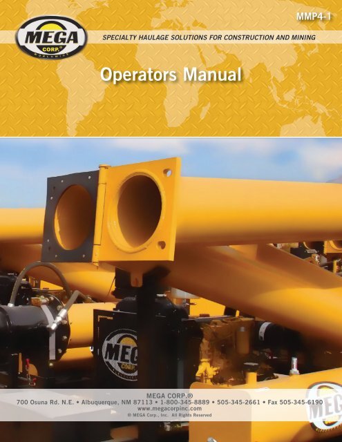
MMP4-1<br />
SPECIALTY HAULAGE SOLUTIONS FOR CONSTRUCTION AND MINING<br />
<strong>Operators</strong> <strong>Manual</strong><br />
MEGA CORP.®<br />
700 Osuna Rd. N.E. • Albuquerque, NM 87113 • 1-800-345-8889 • 505-345-2661 • Fax 505-345-6190<br />
www.megacorpinc.com<br />
® MEGA Corp., Inc. All Rights Reserved
TABLE OF CONTENTS<br />
MMP4(T2)-OPS-1<br />
4 Oct 2011<br />
Definitions and Abbreviations ………………………………………………………… 1-1<br />
Page<br />
System Description ……………………………………………………………………. 2-1<br />
System Operation ……………………………………………………………………… 3-1<br />
Appendix (<strong>Operators</strong> Checklist) ..…………………………………………………….. 4-1<br />
A
MMP4(T2)-OPS-1<br />
4 Oct 2011<br />
TABLE OF CONTENTS<br />
B(Blank)
SECTION 1<br />
Definitions and Abbreviations<br />
MMP4(T2)-OPS-1<br />
4 Oct 2011<br />
<strong>Manual</strong> Usage .,…………………………... 1-1<br />
Warning, Caution & Notes ……………..… 1-1<br />
Shall, Will, Should and May …………..…. 1-1<br />
Contents<br />
Safety Messages ……………………….…. 1-2<br />
Abbreviations …………………………….. 1-5<br />
MMP4 T2 Overview …………….....….…. 1-6<br />
MANUAL USAGE<br />
This technical manual only contains information<br />
required to safely operate the MMP4 powered by<br />
a CAT 3054B diesel engine. See the CAT<br />
3054B Engine Maintenance and <strong>Operators</strong><br />
Safety <strong>Manual</strong> for specific vehicle system<br />
information and maintenance procedures. The<br />
exact location of the hazards and description of<br />
the hazards are reviewed in this section. All<br />
personnel working on or operating the machine<br />
must become familiarized with all the safety<br />
messages.<br />
If your system is not covered in this manual or<br />
are having difficulties please contact the MEGA<br />
Corp. Product Support Group at:<br />
Toll free US 1-800-345-8889<br />
Direct 1-505-345-2661<br />
or visit our website at www.megacorpinc.com<br />
for more detailed contact information.<br />
WARNING, CAUTIONS AND NOTES<br />
The following definitions are found throughout<br />
the manual and apply as follows:<br />
Operating procedures and techniques, which<br />
could result in personal injury and/or loss of life<br />
if not carefully followed.<br />
Operating procedures and techniques, which<br />
could result in damage to equipment if not<br />
carefully followed.<br />
Operating procedures and techniques that are<br />
considered essential to emphasis.<br />
Due to the nature of these processes, ensure that<br />
all safety information, warnings and instructions<br />
are read and understood before any operation or<br />
any maintenance procedures are performed. This<br />
service function takes place with heavy<br />
components and at moderate heights, ensure<br />
proper safety procedures are maintained when<br />
performing this service. Failure to use and<br />
maintain proper safety.<br />
USE OF SHALL, WILL, SHOULD AND<br />
MAY<br />
Shall and Will – Used when application of a<br />
procedure is mandatory.<br />
Should – Used when application of a procedure<br />
is recommended.<br />
May - Used to indicate an acceptable or<br />
suggested means of accomplishment.<br />
1-1
MMP4(T2)-OPS-1<br />
4 Oct 2011<br />
SECTION 1<br />
Definitions and Abbreviations<br />
SAFETY MESSAGES<br />
There are several specific safety messages on<br />
this machine. The exact location of the hazards<br />
and description of the hazards are reviewed in<br />
this section. All personnel working on or<br />
operating the machine must become familiarized<br />
with all the safety messages.<br />
Make sure that all of the safety messages are<br />
legible. Clean the safety messages or replace the<br />
safety messages in you cannot read the words.<br />
Replace the illustrations if the illustrations are<br />
not legible. When you clean the safety<br />
messages, use a cloth, water and soap. Do not<br />
use solvent, gasoline or other harsh chemicals to<br />
clean the safety messages. Solvents, gasoline or<br />
harsh chemicals could loosen the adhesive that<br />
secures the safety messages. Loose adhesive<br />
will allow the safety messages to detach.<br />
Replace any safety message that is damaged or<br />
missing. If a safety message is attached to a part<br />
that is replaced, install a new safety message on<br />
the replacement part.<br />
Toxic Gas Hazard (1)<br />
This safety label is located on the side of the tank<br />
and at all water fill entrances.<br />
Cutting or welding operation on the inside of<br />
the tank can cause the accumulation of toxic<br />
gases. Read and understand instructions and<br />
warnings in the Maintenance <strong>Manual</strong>.<br />
Failure to provide proper ventilation or<br />
breathing apparatus while conducting these<br />
operations may result in serious injury or<br />
death.<br />
Do Not Operate (2)<br />
This safety label is located on the outside of the<br />
front and rear control boxes. (If equipped)<br />
Do not open this control box unless you read<br />
and understand the instructions and warnings<br />
in the Operator and Maintenance <strong>Manual</strong>.<br />
Failure to follow instructions or heed the<br />
warnings could result in serious injury or<br />
death.<br />
1-2
SECTION 1<br />
Definitions and Abbreviations<br />
MMP4(T2)-OPS-1<br />
4 Oct 2011<br />
Backing Runover Hazard (3)<br />
This safety label is located on the rear of the tank<br />
and inside the cab.<br />
Non-Potable (5)<br />
This safety label is located on the side of the tank<br />
and sump drain.<br />
The vehicle is equipped with a back-up alarm.<br />
Alarm must sound when operating this<br />
vehicle in reverse. Failure to maintain a clear<br />
view in the direction of travel could result in<br />
serious injury or death.<br />
Water held within tank is not potable. Do not<br />
use tank for transport of water intended for<br />
human or animal consumption or serious<br />
injury or death may result.<br />
Freezing (4)<br />
This safety label is located on the side of the<br />
tank, at the sump drain, and on the pump.<br />
Do Not Hoist While in Motion (6)<br />
This safety label is located inside the cab.<br />
Drain tank, fill pipe and valve in freezing<br />
weather. Refer to the Operator and<br />
Maintenance <strong>Manual</strong> for the procedure to<br />
follow.<br />
Do not engage hoist cylinders while vehicle is<br />
in motion. Before engaging hoist STOP the<br />
vehicle. Do not engage hoisting cylinders<br />
unless you read and understand the<br />
instructions and warnings in the Operator or<br />
Maintenance <strong>Manual</strong>. Failure to follow<br />
instructions or heed the warnings will result<br />
in injury or death.<br />
1-3
MMP4(T2)-OPS-1<br />
4 Oct 2011<br />
SECTION 1<br />
Definitions and Abbreviations<br />
Fall Hazard (7)<br />
This safety label is located at the top of the front<br />
and rear of the tank.<br />
High Pressure Sprayheads (9)<br />
This safety label is located on the spraybar.<br />
Do not walk on the top of tank without fall<br />
arrest PPE. Serious injury or death could<br />
occur from a fall.<br />
Do not operate sprayheads until all personnel<br />
are a safe distance away from the vehicle.<br />
Rotating Shaft (8)<br />
This safety label is located on the pump.<br />
High Pressure Monitor (10)<br />
This safety label is located on top of the cab<br />
control box.<br />
Do not place your hand or tools within pump<br />
bell while pump is rotating and/or pressure<br />
held within the motor supply hose. Refer to<br />
the Operator and Maintenance <strong>Manual</strong> for<br />
the procedures to operate and maintain the<br />
pump. Failure to follow proper procedures<br />
could result in serious injury.<br />
Do not operate the monitor until all personnel<br />
are a safe distance away from the vehicle.<br />
1-4
SECTION 1<br />
Definitions and Abbreviations<br />
MMP4(T2)-OPS-1<br />
4 Oct 2011<br />
High Pressure Motor (11)<br />
This safety label is located on the hydraulic<br />
motor.<br />
Hydraulic motor and supply lines contain oil<br />
under high pressure. Improper removal and<br />
repair procedures could cause severe injury.<br />
To remove or repair, instructions in the<br />
Maintenance <strong>Manual</strong> must be followed.<br />
Confined Space (12)<br />
This safety label is located near water tank<br />
access and fill ports.<br />
ABBREVIATIONS<br />
cc – Cubic Centimeters<br />
CCW – Counter Clockwise<br />
CW - Clockwise<br />
fl. oz. – Fluid Ounce<br />
FT - Feet<br />
FPM – Feet Per Minute<br />
GPM – Gallons Per Minute<br />
IN/SQ FT – Inches per Square Feet<br />
KM-H – Kilometers Per Hour<br />
Kg – kilograms<br />
kPa - Kilopascals<br />
l – liters<br />
lpm – Liters per minute<br />
LT – Left as viewed from the operators<br />
position facing forward<br />
m - meters<br />
MPH – Miles Per Hour<br />
MMP – MEGA Mobile Pump<br />
Nm – Newton meters of torque<br />
psi - pounds per square inch<br />
RPM – Revolutions Per Minute<br />
RT – Right as viewed from the operators<br />
position facing forward<br />
SQ FT – Square Feet<br />
VDC – Volts, Direct Current<br />
Do not enter confined spaces without<br />
following established site specific<br />
procedures. Failure to follow proper safety<br />
procedures will result in serious injury or<br />
death.<br />
1-5
MMP4(T2)-OPS-1<br />
4 Oct 2011<br />
SECTION 1<br />
Definitions and Abbreviations<br />
1<br />
MMP4 T2 Overview<br />
13 16<br />
15<br />
14<br />
3<br />
2<br />
5<br />
8<br />
7<br />
6<br />
9 10<br />
11<br />
3<br />
4<br />
16<br />
15<br />
14<br />
4<br />
13 12<br />
5<br />
8<br />
6<br />
10 11<br />
7<br />
6<br />
Tire and Rim Assembly<br />
1<br />
Discharge Boom<br />
7<br />
Fender<br />
12<br />
Inlet Debris Screen<br />
2<br />
Vacuum Break<br />
8<br />
5o Gallon Diesel Fuel Tank<br />
13<br />
Axial Water Pump<br />
3<br />
Tow Hitch<br />
9<br />
Discharge Boom Lift Cylinder<br />
14<br />
Inlet Boom<br />
4<br />
CAT 3054 Diesel Engine<br />
10<br />
Tail Lights<br />
15<br />
Hydraulic Control Valve<br />
5<br />
Landing Gear (3)<br />
11<br />
Hydraulic Oil Tank<br />
16<br />
Engine Control Box<br />
1-6
SECTION 2<br />
System Description<br />
MMP4(T2)-OPS-1<br />
4 Oct 2011<br />
MMP4 Description and Usage ………… 2-1<br />
MMP4 Frame …………………………… 2-1<br />
Hydraulics ……………………………….. 2-1<br />
Contents<br />
Axial Water Pump ………………………. 2-2<br />
Engine Control Box ……………………... 2-2<br />
MMP4 DESCRIPTION AND USAGE<br />
MMP4 FRAME<br />
The MMP4 frame is the back bone of the unit,<br />
manufactured using rectangular tubing.<br />
Attached to the frame is the 6,000 lbs (2,725<br />
kg) capacity axle assembly, boom supporting<br />
structures, hydraulic and fuel tanks, engine<br />
assembly including a battery and tool storage<br />
box, a fold away hitch assembly, rear walk<br />
way, fenders and DOT rated lighting.<br />
The MMP4 is designed to be towed behind a<br />
typical ¾ ton or 1 ton capacity pickup truck.<br />
The MMP4 can be transported over the road to<br />
just about any water holding pond area used for<br />
filling water distribution equipment.<br />
The MMP4 can be set up, made ready for<br />
operation and reconfigured for transport by 1<br />
person and simple hand tools. The MMP4’s<br />
primary usage is to lift water from a water<br />
holding pond and discharge the water into the<br />
fill port on water haulage equipment. The<br />
MMP4 is equipped with a Diesel engine with<br />
an integrated hydraulic pump and oil cooler, 50<br />
gallon (190 liter) diesel fuel tank, 32 gallon (87<br />
liter) hydraulic oil reservoir, 3 circuit hydraulic<br />
control valve, DOT rated lighting, 6,000 pound<br />
(2,725 kg) capacity axle and tire combination, 3<br />
point stabilizing jacking system, hydraulically<br />
operated inlet and discharge boos, 12” axial<br />
hydraulic drive water pump and a folding hitch<br />
assembly. The MMP4 is capable of lifting<br />
water approximately 25’ (7.62 meters) with a<br />
discharge port approximately 17’ (5.2 meters)<br />
above ground level.<br />
HYDRAULICS<br />
The hydraulic system of the MMP4 consists of<br />
an engine mounted hydraulic pump, 35 gallon<br />
(135 liter) hydraulic oil tank equipped with an<br />
inlet screen, return oil diffuser, external shut off<br />
valve, oil level sight glass and a breather<br />
equipped filler cap. The balance of the<br />
hydraulic system is designed with a 10 micron<br />
rated return oil filter, 3 spool hydraulic control<br />
valve with pressure regulation capability, a<br />
hydraulic oil cooler equipped with a bypass<br />
valve to protect against hydraulic shock when<br />
the oil is cold, hydraulically driven submergible<br />
12” axial water pump, hydraulic cylinders to<br />
lift the inlet and discharge booms.<br />
2-1
MMP4(T2)-OPS-1<br />
4 Oct 2011<br />
AXIAL WATER PUMP<br />
SECTION 2<br />
System Description<br />
ENGINE CONTROL BOX<br />
Engine Coolant<br />
Temperature<br />
Gauge<br />
Tachometer<br />
Engine<br />
Oil<br />
Pressure<br />
Gauge<br />
Emergency<br />
Stop<br />
Button<br />
The 12” axial, hydraulic drive water pump used<br />
on the MMP4 is mounted to a flange mounted<br />
on the inlet boom extension. The pump<br />
includes a heavy debris inlet screen to prevent<br />
any large pieces of debris from entering the<br />
pump and the water tanker to prevent possible<br />
damage to the spray systems and water pumps.<br />
Mounted to the water pump below the inlet<br />
screen is a protector plate, this plate can<br />
prevent the water pump inlet screen from<br />
setting directly on the bottom of the pond and<br />
picking up unwanted debris, dirt or partially<br />
restricting the intake of the water pump. When<br />
submerged in the holding pond the inlet of the<br />
water pump must be 2.5’ (0.762 meters) below<br />
the surface of the pond at all times while<br />
pumping water. The water pump hydraulic<br />
drive motor is connected to the hydraulic<br />
control valve by 2 hydraulic hoses, this routes<br />
hydraulic oil to the water pump drive motor<br />
when the control valve spool is shifted to the<br />
ON position returns oil back to the hydraulic<br />
control valve then to the 10 micron rated<br />
hydraulic oil filter. The water pump discharge<br />
volume is proportional to the engine rpm (e.g;<br />
the higher the engine rpm the larger the volume<br />
of water the pump will discharge). The water<br />
pump contains 2 oil reservoirs to lubricate the<br />
shaft bearings.<br />
Battery<br />
Volt<br />
Meter<br />
Engine Start – Stop Key<br />
Switch<br />
The engine control box controls and monitors<br />
the main engine functions. It is equipped with:<br />
• Magnetic safety switch (MURPHY) that will<br />
shut the engine OFF if the engine coolant<br />
temperature reads too high or the engine oil<br />
pressure reads too low.<br />
• Oil pressure gauge for monitoring the engine<br />
oil pressure.<br />
System<br />
Electrical<br />
Fuse<br />
MURPHY<br />
Switch<br />
Engine Preheat Button<br />
Hand Throttle<br />
• Engine coolant temperature for monitoring<br />
the engine coolant temperature.<br />
• Tachometer to monitor the engine rpms or<br />
speed.<br />
•<br />
2-2
SECTION 2<br />
System Description<br />
MMP4(T2)-OPS-1<br />
4 Oct 2011<br />
Battery voltage meter to monitor the battery<br />
voltage.<br />
• Pre-heater button to assist with starting when<br />
the ambient temperatures are low.<br />
• Emergency stop button to shut the engine off<br />
in case of an emergency.<br />
• System electrical fuse to protect the electrical<br />
system in case of an electrical malfunction.<br />
• Hand throttle to adjust the engine operating<br />
rpms.<br />
2-3
MMP4(T2)-OPS-1<br />
4 Oct 2011<br />
SECTION 2<br />
System Description<br />
2-4(Blank)
SECTION 3<br />
System Operation<br />
MMP4(T2)-OPS-1<br />
4 Oct 2011<br />
MMP4 Location ……………………….. 3-1<br />
Normal Operation Configuration ………. 3-1<br />
Contents<br />
Operation ……………..…………..……. 3-7<br />
Towing Configuration ………………….. 3-8<br />
MMP4 LOCATION<br />
1. Locate a suitable set up location based on<br />
the type of equipment being used at the job<br />
site, access and traffic flow to the MMP4<br />
fill site.<br />
Failure to observe and follow the<br />
recommendations below may result in<br />
damage to the MMP4, the water holding<br />
pond, serious personal injury or death.<br />
A. Ensure MMP4 water pump intake is at<br />
least 2.5’ (0.762 meters) below the<br />
surface of the pond.<br />
B. Ensure the MMP4 is located on a firm,<br />
level footing and water flow spillage will<br />
not erode the pad that the MMP4 is set up<br />
on.<br />
C. Ensure there is enough safe access to the<br />
control panel for the operator to prevent<br />
accidental slips and falls.<br />
CONFIGURING THE MMP4 FOR<br />
NORMAL OPERATION<br />
When the MMP4 is placed in the desirable<br />
position for usage:<br />
1. Chock wheels to prevent unwanted<br />
movement of MMP4.<br />
2. Lower the 2 front landing gear to the<br />
ground by lowering the inner leg. The<br />
inner leg can be lowered by removing the<br />
safety pin and allowing the insert to lower<br />
to the ground. Locate the next available<br />
adjusting hole in the leg and reinsert the<br />
locking pin, ensure the pin has the safety<br />
lock in place and properly installed before<br />
placing weight on the leg.<br />
3. Lower the landing gear by moving the<br />
crank on top of the leg in a clockwise<br />
direction, alternating between the 2 forward<br />
landing gear.<br />
D. Ensure the ponds liner (If applicable) is<br />
not loose or damaged.<br />
E. If the pond does not have a liner ensure<br />
the MMP4 water pump is not submerged<br />
in the silt or mud at the bottom.<br />
Ensure the MMP4 is properly secured and<br />
the wheels are chocked to prevent the<br />
MMP4 from moving when uncoupled to<br />
the tow vehicle. Failure to ensure MMP4<br />
will not move when uncoupled from tow<br />
vehicle can result in serious personal<br />
injury or death.<br />
3-1
MMP4(T2)-OPS-1<br />
4 Oct 2011<br />
SECTION 3<br />
System Operation<br />
4. Uncouple the hitch from the tow vehicle<br />
by lifting up the safety lever on the tow<br />
coupling.<br />
Safety Lever<br />
Released<br />
9. Check safety chain locking pins to ensure<br />
they are tight and locked in place.<br />
Safety Chain<br />
Safety Chain Lock Pin<br />
Tow Coupling<br />
5. Alternately raise the MMP4s 2 forward<br />
landing gear until the tow coupling clears<br />
the tow vehicle ball hitch.<br />
6. Remove the safety chains, disconnect the<br />
MMP4 light cable and move tow vehicle<br />
to a safe area away from the MMP4 set<br />
up.<br />
7. Lower rear landing gear to ground and<br />
level MMP4, ensure the unit is stable and<br />
secure.<br />
8. Ensure the MMP4 is level before<br />
deploying the booms.<br />
Ensure safety chains are taught, lock pins<br />
are placed to retain safety chain and the<br />
tethered cotter pin is securely inserted into<br />
the hole at the end of the lock pin. Failure<br />
to ensure the booms are secured using the<br />
safety chains and ensuring the safety chains<br />
are positioned correctly and the pin is<br />
completely seated may result in the boom<br />
swinging out of position or falling causing<br />
serious personal injury or death.<br />
10. Locate and tie a guide rope to the discharge<br />
boom vacuum break.<br />
Vacuum Break<br />
3-2
SECTION 3<br />
System Operation<br />
MMP4(T2)-OPS-1<br />
4 Oct 2011<br />
11. Remove the center travel lock bolt and<br />
safety chain from the center upright on the<br />
frame.<br />
Travel Lock Bolt<br />
13. Locate 2 flange retaining bolts (typically<br />
placed inside of the battery box), locate 2<br />
wrenches to tighten the flange bolts.<br />
14. Using the rope, swing the discharge boom<br />
to align the flanges.<br />
15. Insert 2 flange bolts in the holes of the<br />
flange, install nuts to the bolts.<br />
Safety Chain<br />
Travel Lock Bolt<br />
Safety Chain<br />
12. Remove the forward travel lock bolt near<br />
the discharge boom hinge.<br />
15. Tighten the flange retaining bolts until the<br />
flanges are parallel and secure.<br />
Forward Travel Lock Bolt<br />
16. Remove the guide rope from the discharge<br />
boom.<br />
3-3
MMP4(T2)-OPS-1<br />
4 Oct 2011<br />
SECTION 3<br />
System Operation<br />
17. Install the fabric discharge sock to the<br />
vacuum break by slipping the retaining<br />
hooks through the grommets in the sock.<br />
The sock can be stored in the battery box<br />
when MMP4 is ready for travel.<br />
19. Pull hitch straight out of frame tube until<br />
the rear hole of the insert lines up with the<br />
forward hole in the frame, insert 1 shear<br />
pin.<br />
18. Fold hitch away by removing the 2 shear<br />
pins and the safety clips.<br />
20. Rotate hitch CCW about 90° to position it<br />
out of the path of water haulers to be filled<br />
by the MMP4.<br />
3-4
SECTION 3<br />
System Operation<br />
MMP4(T2)-OPS-1<br />
4 Oct 2011<br />
21. Insert the second shear pin into the empty<br />
hole on the frame assembly and install both<br />
safety pins.<br />
26. Stand behind water pump and guide the<br />
inlet boom to full extension.<br />
Use caution when extending the inlet boom.<br />
Never stand in front of the water pump<br />
when extending boom. Standing in front of<br />
the inlet boom when extending may cause<br />
the operator to lose their balance and be<br />
impacted by the boom when it swings this<br />
can cause serious personal injury or death.<br />
22. Ensure the safety chain on the inlet boom<br />
cylinder is tight and the shear pin is fully<br />
seated and the safety pin is in place.<br />
23. Remove the retaining bolt from the travel<br />
lock on the inlet boom.<br />
27. When the inlet boom is fully extended<br />
insert and secure the 2 flange bolt<br />
assemblies.<br />
28. Tighten the bolts until the flanges are<br />
parallel.<br />
29. Loosen the Victaulic coupling 1 to 2 turns<br />
and loosen the pipe mounts to allow the<br />
booms to pivot.<br />
24. Remove the safety strap and the safety<br />
chain from the water pump.<br />
Victaulic<br />
Coupling Bolt<br />
25. Locate and secure the 2 flange bolt<br />
assemblies.<br />
Pipe Mount Bolts<br />
3-5
MMP4(T2)-OPS-1<br />
4 Oct 2011<br />
SECTION 3<br />
System Operation<br />
30. Check hydraulic oil level, adjust as<br />
required.<br />
31. Start engine, allow the engine to idle for a<br />
couple of minutes to stabilize the engine oil<br />
pressure and to begin to warm the hydraulic<br />
oil.<br />
32. Operate the PUMP INLET lever in the UP<br />
position until the hydraulic cylinder is fully<br />
retracted and the safety chain is slack. It<br />
may be necessary to increase the engine<br />
idle speed with the hand throttle to move<br />
the inlet boom UP.<br />
35. Lower pump inlet until the inlet of the<br />
water pump is at least 2.5’ (0.762 meters)<br />
below the surface of the water, ensure the<br />
water pump is a t least 18” (0.46 meters)<br />
above the bottom of the pond and not in<br />
contact with the pond liner.<br />
36. Install the safety chain shear pin and keeper<br />
to avoid misplacing the pin while the<br />
MMP4 is in operation.<br />
33. Place the PUMP INLET lever in the<br />
NEUTRAL position and remove the safety<br />
chain shear pin.<br />
37. Move the lever for the discharge boom to<br />
the UP position and hold as shown below.<br />
34. Slowly operate lever for PUMP INLET<br />
‘DOWN’ as shown below.<br />
3-6
SECTION 3<br />
System Operation<br />
MMP4(T2)-OPS-1<br />
4 Oct 2011<br />
38. When the discharge boom has reached the<br />
full UP angle move the lever to the neutral<br />
position.<br />
39. Secure the discharge boom safety chain.<br />
OPERATING THE MMP4<br />
1. Move water tanker into position with the<br />
fill port directly under the discharge boom<br />
fill sock.<br />
2. Check engine according to the CAT 3054<br />
Operations and Maintenance <strong>Manual</strong> for<br />
pre-operation checks.<br />
40. Ensure the safety chain is tight, the safety<br />
chain shear pin is fully seated and the safety<br />
keeper pin is installed.<br />
Ensure the safety chains are tensioned<br />
properly and shear pins and keepers are<br />
installed. Failure to ensure the safety<br />
chains are installed and secured properly<br />
may result in serious personal injury or<br />
death if the boom falls.<br />
41. Tighten the Victaulic coupling bolts and<br />
pipe mounting bolts that were previously<br />
loosened for tube movement.<br />
3. Ensure the unit is safe to operate.<br />
4. Start engine.<br />
5. Let engine idle to stabilize oil pressures and<br />
temperatures.<br />
6. Engage the MMP4 water pump.<br />
7. Move the PUMP lever to the ON position<br />
as shown below (a detent will hold the lever<br />
it the ON position until it is physically<br />
moved to OFF).<br />
42. Return the engine to LOW idle.<br />
43. Shut off engine.<br />
44. Stow and secure the travel lock bolts and<br />
hardware in the battery box tool<br />
compartment.<br />
45. Secure engine control box.<br />
3-7
MMP4(T2)-OPS-1<br />
4 Oct 2011<br />
SECTION 3<br />
System Operation<br />
8. Slowly increase the engine idle speed until<br />
the desired water flow is reached.<br />
The MMP4 hand throttle can be operated 2<br />
ways, by depressing the red button in the<br />
center of the hand throttle knob and pulling<br />
the knob out until the desired engine rpm is<br />
reach and releasing the button or by rotating<br />
the hand throttle knob counter clockwise<br />
until the desired engine rpm is reached. If<br />
the hand throttle fails to stay at the set rpm<br />
adjust the locking collar until the hand<br />
throttle stay at the set position.<br />
Hand Throttle Knob<br />
Red<br />
Button<br />
Locking Collar<br />
9. Observe the water filling the tank, when the<br />
tanker is filled to the desired level, return<br />
the MMP4 to LOW idle by depressing the<br />
red button on the hand throttle and pushing<br />
the knob IN until the engine is at low idle.<br />
10. Move the pump lever to the OFF position.<br />
11. Shut the engine OFF.<br />
12. Move the water tanker away from the<br />
MMP4.<br />
DISASSEMBLING THE MMP4 FOR<br />
TRANSPORT<br />
1. Ensure the MMP4 is safe for operation.<br />
2. Perform all pre-operation checks.<br />
3. Acquire the tools used for assembly.<br />
4. Reverse the set up procedure to return the<br />
MMP4 to the towing configuration.<br />
Hand Throttle at LOW idle<br />
Ensure that the inlet and discharge boom<br />
hydraulic cylinders are preloaded in the full<br />
RAISE position before removing the safety<br />
chain shear pins. Failure to ensure the<br />
cylinders are preloaded may result in the<br />
boom falling causing serious personal<br />
injury or death.<br />
Hand Throttle at HIGH idle<br />
Ensure all travel lock bolts, safety chains,<br />
shear pins, and shear pin safety pins are<br />
secured and installed properly before<br />
transporting the MMP4. Failure to ensure<br />
all safety equipment and procedures are<br />
installed and followed may result in<br />
damage to the MMP4 or tow vehicle.<br />
3-8
MMP4(T2)-OPS-1<br />
4 Oct 2011<br />
SECTION 4<br />
Appendix<br />
MMP4(T2)-OPS(CL)-1<br />
4 Oct 2011<br />
MMP4(T2)<br />
OPERATORS<br />
CHECKLIST<br />
4-1
MMP4(T2)-OPS-1<br />
4 Oct 2011<br />
SECTION 4<br />
Appendix<br />
MMP4(T2)-OPS(CL)-1<br />
4 Oct 2011<br />
TABLE OF CONTENTS<br />
Title<br />
Page<br />
1. BEFORE OPERATIONS……..…… N-2<br />
2. OPERATIONS…………………….. N-5<br />
3. AFTER OPERATIONS……………. N-7<br />
4. BEFORE TRANSPORTING MMP4 . N-8<br />
N-1<br />
4-2
MMP4(T2)-OPS-1<br />
4 Oct 2011<br />
SECTION 4<br />
Appendix<br />
MMP4(T2)-OPS(CL)-1<br />
4 Oct 2011<br />
BEFORE OPERATIONS<br />
These procedures are used to perform a walk-around<br />
inspection of the MEGA mobile water pump before<br />
use or beginning of the shift. This inspection is in<br />
addition to and does not replace the vehicle<br />
manufacturer’s inspection requirements.<br />
1. Chocks – As Required<br />
2. Landing Gear – Secure and Stabile<br />
3. Engine Control Switches – SET OFF<br />
4. Boom Safety Chains – SECURE AND<br />
PROPERLY ADJUSTED<br />
5. Hydraulic Oil Tank – CHECKED AND<br />
SECURED<br />
6. Hydraulic Oil Level - SERVICED<br />
7. Hydraulic Oil Quality – CLEAR<br />
8. Ball Valve On hydraulic Tank – OPEN<br />
9. Hydraulic Hoses and Fittings – SECURE AND<br />
NO LEAKS PRESENT<br />
N-2<br />
4-3
MMP4(T2)-OPS-1<br />
4 Oct 2011<br />
SECTION 4<br />
Appendix<br />
MMP4(T2)-OPS(CL)-1<br />
4 Oct 2011<br />
10. Hydraulic Pump – CHECKED AND SECURE<br />
11. Victaulic Coupling and Boom Mounts –<br />
CHECKED AND SECURE<br />
12. Boom Hydraulic Cylinders – CHECKED FOR<br />
SECURITY AND LEAKS<br />
13. Boom Flanges – CHECKED AND SECURED<br />
14. Discharge Sock – CHECKED AND SECURE<br />
15. Diesel Fuel Tank – PROPER LEVEL, SHUT<br />
OFF VALVES OPEN, CHECKED AND<br />
SECURE<br />
16. Fold Away Hitch – CHECKED AND SECURED<br />
17. Hydraulic Oil Cooler – CHECKED AND<br />
SECURED<br />
18. Diesel Engine – CHECKED AND SERVICED<br />
IN ACCORDANCE WITH MANUFACTURE<br />
OPERATIONS MANUAL AND SECURED<br />
19. Battery and Battery Box – CHECKED AND<br />
SECURED<br />
N-3<br />
4-4
MMP4(T2)-OPS-1<br />
4 Oct 2011<br />
SECTION 4<br />
Appendix<br />
MMP4(T2)-OPS(CL)-1<br />
4 Oct 2011<br />
20. Engine Control Box – CHECKED AND<br />
SECURED<br />
21. Hand Throttle Control – CHECKED AND SECURE<br />
22. Hydraulic Control Valve – CHECKED, SECURE<br />
AND NO LEAKS PRESENT<br />
23. Boom Positions – POSITIONS CHECKED AND<br />
SECURED<br />
24. Water Pump – CHECKED, SECURE AND NO<br />
LEAKS PRESENT<br />
25. Water Equipment Loading Access – CLEAR,<br />
EASILY ACCESSIBLE AND FREE FROM<br />
OBSTRUCTIONS<br />
N-4<br />
4-5
MMP4(T2)-OPS-1<br />
4 Oct 2011<br />
SECTION 4<br />
Appendix<br />
MMP4(T2)-OPS(CL)-1<br />
4 Oct 2011<br />
OPERATION<br />
Use these procedures to safely operate the MMP4<br />
when loading a water tanker.<br />
1. Enter water filling area.<br />
2. Position water tanker fill port directly under<br />
discharge sock.<br />
3. Secure vehicle.<br />
Ensure vehicle is safe and secured before exiting<br />
cab, [e.g; Transmission in NEUTRAL, Park brake<br />
ON, Engine OFF, Chock Blocks (if required)].<br />
Failure to ensure vehicle is safe to exit when<br />
dismounting cab may result in personal injury or<br />
death.<br />
4. Exit vehicle<br />
5. Hydraulic Control Valve Levers - OFF<br />
6. Start Engine – ON/RUN<br />
N-5<br />
4-6
SECTION 4<br />
Appendix<br />
MMP4(T2)-OPS-1<br />
4 Oct 2011<br />
7. Engine RPM – LOW IDLE<br />
8. PUMP Lever – ON<br />
MMP4(T2)-OPS(CL)-1<br />
4 Oct 2011<br />
Engaging/disengaging the water pump above<br />
LOW IDLE may result in water pump component<br />
damage and reduced service life.<br />
9. Slowly increase engine RPM until desired fill rate<br />
is achieved.<br />
10. Observe water level in water tanker being<br />
filled, when desired water level is reached,<br />
reduce engine RPM to LOW IDLE.<br />
11. PUMP Lever – OFF<br />
12. Engine - OFF<br />
13. Mount vehicle operators compartment.<br />
14. Exit filling area.<br />
N-6<br />
4-7
MMP4(T2)-OPS-1<br />
4 Oct 2011<br />
SECTION 4<br />
Appendix<br />
MMP4(T2)-OPS(CL)-1<br />
4 Oct 2011<br />
AFTER OPERATIONS<br />
These procedures are used to perform a walk-around<br />
inspection after using the MEGA Mobile Pump. This<br />
inspection is in addition to and does not replace the<br />
vehicle manufacturer’s inspection requirements.<br />
1. Diesel Engine – CHECKED AND SECURED<br />
2. Hydraulic System – CHECKED, SERVICED AND<br />
NO LEAKS PRESENT<br />
3. MMP4 Frame – CHECKED AND SECURED<br />
4. MMP4 Location and Set Up – SECURE AND<br />
STABILE<br />
5. Engine Control Box – CHECKED AND<br />
SECURED<br />
N-7<br />
4-8
SECTION 4<br />
Appendix<br />
MMP4(T2)-OPS-1<br />
4 Oct 2011<br />
MMP4(T2)-OPS(CL)-1<br />
4 Oct 2011<br />
BEFORE TRANSPORTING MMP4<br />
These procedures are used to perform a walk-around<br />
inspection on the MMP4 prior to transporting the unit.<br />
1. Ensure unit is safe for operation.<br />
2. Engine – STAR/RUN, LOW IDLE<br />
3. Lift INTAKE Boom - COMPLETED<br />
4. Remove INTAKE Boom Flange Bolts – REMOVED<br />
AND SECURED<br />
5. Install and secure INTAKE Boom Travel Straps,<br />
Safety Chains, Chains and Bolts – CHECKED AND<br />
SECURED<br />
6. Lift and Preload Discharge cylinder, release safety<br />
chain - COMPLETED<br />
7. Lower DISCHARGE Boom- LOWERED<br />
8. Remove DISCHARGE Boom Flange Bolts –<br />
REMOVED AND SECURED<br />
N-8<br />
4-9
MMP4(T2)-OPS-1<br />
4 Oct 2011<br />
SECTION 4<br />
Appendix<br />
MMP4(T2)-OPS(CL)-1<br />
4 Oct 2011<br />
9. Install and secure DISCHARGE Boom Travel Lock<br />
Bolts and Chain – CHECKED AND SECURED<br />
10. Engine – OFF<br />
11. Move Tow Hitch to TRAVEL Position and Secure –<br />
CHECKED AND SECURED<br />
12. Diesel Fuel Petcocks – OFF<br />
13. Hydraulic Oil Tank Ball Valve – OFF<br />
14. Rear Landing Gear – UP AND SECURE<br />
15. Couple Tow vehicle to MMP4 Ball Coupling –<br />
CHECKED AND SECURE<br />
16. Raise and Secure Front Landing Gear – UP AND<br />
SECURE<br />
17. Connect Trailer Light Cord – CHECKED AND<br />
CONNECTED<br />
18. Check all MMP4 Lights – CHECKED AND<br />
OPERATIONAL<br />
N-9<br />
4-10
SECTION 4<br />
Appendix<br />
MMP4(T2)-OPS-1<br />
4 Oct 2011<br />
MMP4(T2)-OPS(CL)-1<br />
4 Oct 2011<br />
19. Inflate Tire to 80 psi – CHECKED AND<br />
SERVICED<br />
20. Torque Lug Nuts to 80-90 ft/lbs<br />
(110 – 125 Nm) – SERVICED AND SECURED<br />
21. Ball Coupling Lock – CHECKED AND SECURE<br />
N-10<br />
4-11
MMP4(T2)-OPS-1<br />
4 Oct 2011<br />
SECTION 4<br />
Appendix<br />
4-12(Blank)