Regulating valve âCocon Qâ with automatic flow control
Regulating valve âCocon Qâ with automatic flow control
Regulating valve âCocon Qâ with automatic flow control

You also want an ePaper? Increase the reach of your titles
YUMPU automatically turns print PDFs into web optimized ePapers that Google loves.
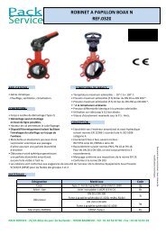
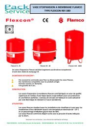
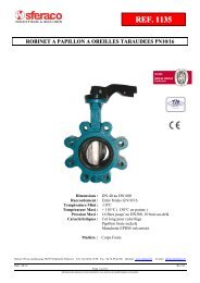
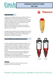
<strong>Regulating</strong> <strong>valve</strong> “Cocon Q”<br />
<strong>with</strong> <strong>automatic</strong> <strong>flow</strong> <strong>control</strong><br />
The Oventrop Quality Management<br />
System is certified to DIN-EN-ISO 9001<br />
Technical information<br />
Application:<br />
The Oventrop regulating <strong>valve</strong> “Cocon Q” is a <strong>valve</strong> combination<br />
consisting of an <strong>automatic</strong> regulator (nominal value manually<br />
adjust able) and a regulating <strong>valve</strong>. The regulating <strong>valve</strong> can be<br />
equipped <strong>with</strong> an actuator, temperature <strong>control</strong>ler or manual head<br />
(connection thread M 30 x 1.5).<br />
The <strong>valve</strong> is used for the hydronic balancing and temperature<br />
<strong>control</strong> of appliances or sections of the system in chilled ceiling,<br />
Fan-Coil, convector, central heating and surface heating systems.<br />
Technical data:<br />
Performance data<br />
Max. working temperature t s :<br />
Min. working temperature t s :<br />
Max. working pressure p s :<br />
Differential pressure:<br />
+120°C<br />
-10°C<br />
16 bar (1600 kPa)<br />
“p1”-“p3”: min. differential<br />
pressure depending on the<br />
nominal setting<br />
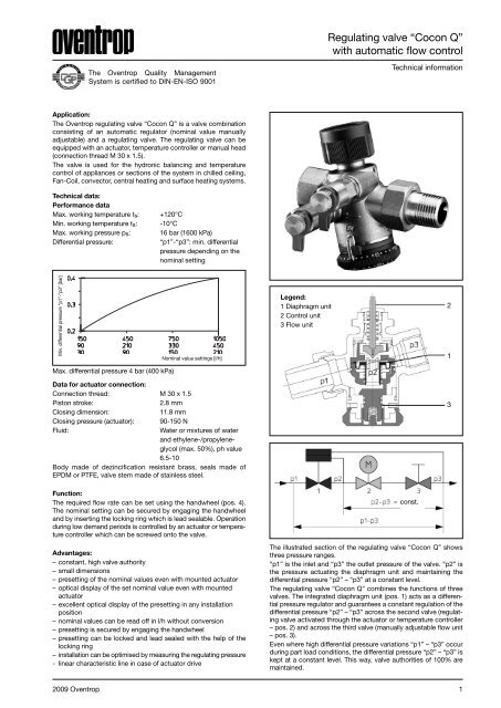
Min. differential pressure “p1”-“p3” [bar]<br />
Nominal value settings [l/h]<br />
Legend:<br />
1 Diaphragm unit<br />
2 Control unit<br />
3 Flow unit<br />
2<br />
1<br />
Max. differential pressure 4 bar (400 kPa)<br />
Data for actuator connection:<br />
Connection thread: M 30 x 1.5<br />
Piston stroke:<br />
2.8 mm<br />
Closing dimension:<br />
11.8 mm<br />
Closing pressure (actuator): 90-150 N<br />
Fluid:<br />
Water or mixtures of water<br />
and ethylene-/propyleneglycol<br />
(max. 50%), ph value<br />
6.5-10<br />
Body made of dezincification resistant brass, seals made of<br />
EPDM or PTFE, <strong>valve</strong> stem made of stainless steel.<br />
3<br />
Function:<br />
The required <strong>flow</strong> rate can be set using the handwheel (pos. 4).<br />
The nominal setting can be secured by engaging the handwheel<br />
and by inserting the locking ring which is lead sealable. Operation<br />
during low demand periods is <strong>control</strong>led by an actuator or tempera -<br />
ture <strong>control</strong>ler which can be screwed onto the <strong>valve</strong>.<br />
Advantages:<br />
– constant, high <strong>valve</strong> authority<br />
– small dimensions<br />
– presetting of the nominal values even <strong>with</strong> mounted actuator<br />
– optical display of the set nominal value even <strong>with</strong> mounted<br />
actuator<br />
– excellent optical display of the presetting in any installation<br />
position<br />
– nominal values can be read off in l/h <strong>with</strong>out conversion<br />
– presetting is secured by engaging the handwheel<br />
– presetting can be locked and lead sealed <strong>with</strong> the help of the<br />
locking ring<br />
– installation can be optimised by measuring the regulating pressure<br />
- linear characteristic line in case of actuator drive<br />
const.<br />
The illustrated section of the regulating <strong>valve</strong> “Cocon Q” shows<br />
three pressure ranges.<br />
“p1” is the inlet and “p3” the outlet pressure of the <strong>valve</strong>. “p2” is<br />
the pressure actuating the diaphragm unit and maintaining the<br />
differential pressure “p2” – “p3” at a constant level.<br />
The regulating <strong>valve</strong> “Cocon Q” combines the functions of three<br />
<strong>valve</strong>s. The integrated diaphragm unit (pos. 1) acts as a differential<br />
pressure regulator and guarantees a constant regulation of the<br />
differential pressure “p2” – “p3” across the second <strong>valve</strong> (regulating<br />
<strong>valve</strong> activated through the actuator or temperature <strong>control</strong>ler<br />
– pos. 2) and across the third <strong>valve</strong> (manually adjustable <strong>flow</strong> unit<br />
– pos. 3).<br />
Even where high differential pressure variations “p1” – “p3” occur<br />
during part load conditions, the differential pressure “p2” – “p3” is<br />
kept at a constant level. This way, <strong>valve</strong> authorities of 100% are<br />
maintained.<br />
2009 Oventrop 1
<strong>Regulating</strong> <strong>valve</strong> “Cocon Q”<br />
<strong>with</strong> <strong>automatic</strong> <strong>flow</strong> <strong>control</strong><br />
Flow rate [l/h]<br />
Differential pressure “p1”-“p3” [bar]<br />
The maximum <strong>flow</strong> volume (V)<br />
·<br />
<strong>with</strong>in the <strong>control</strong> range is set <strong>with</strong><br />
the help of the handwheel. During low demand periods, the <strong>flow</strong><br />
rate is regulated to the required value by the stroke position of the<br />
regulating <strong>valve</strong>.<br />
H2 H1<br />
Effective <strong>valve</strong> lift [%]<br />
· Flow rate V [l/h]<br />
L1<br />
DN L H1 H2<br />
15 65 52 48<br />
20 74 52 48<br />
The regulating <strong>valve</strong> “Cocon Q” has a linear characteristic line<br />
which is advantageous when using actuators (electrothermal or<br />
electromotive) which also have linear stroke behaviour. In general,<br />
the <strong>valve</strong> may also be combined <strong>with</strong> a temperature <strong>control</strong>ler.<br />
Dimensions:<br />
L2<br />
DN L1 L2 H1 H2<br />
15 70 98.5 52 48<br />
20 74 106 52 48<br />
L1<br />
H2 H1<br />
Actuators:<br />
The regulating <strong>valve</strong>s “Cocon Q” can be used <strong>with</strong> the following<br />
Oventrop actuators (M 30 x 1.5):<br />
Actuator Voltage<br />
Control<br />
2 point 3 point Proportional<br />
Electrothermal<br />
240 V 101 28 16/26 1012951 (0-10 V)<br />
Electromotive<br />
230 V<br />
240 V<br />
101 28 15/25/17<br />
101 27 01 1012700 (0-10V)<br />
230 V<br />
EIB<br />
LON<br />
101 27 10 101 27 03<br />
115 60 65/66<br />
115 70 65<br />
The regulating <strong>valve</strong>s “Cocon Q” can also be used <strong>with</strong> Oventrop<br />
thermostats and temperature <strong>control</strong>lers.<br />
Installation:<br />
– The direction of <strong>flow</strong> must conform to the arrow on the <strong>valve</strong><br />
body.<br />
– The <strong>valve</strong> may be installed in any position (electric actuators<br />
may not be installed vertically downwards).<br />
– Do not use any lubricant or oil when installing the <strong>valve</strong> as these<br />
may destroy the <strong>valve</strong> seals. If necessary, all dirt particles and<br />
lubricant or oil residues must be removed from the pipework by<br />
flushing the latter.<br />
– Any tension applied on the <strong>valve</strong> by the pipework must be<br />
avoided.<br />
– When choosing the operating fluid, the latest technical development<br />
must be considered (e.g. VDI 2035).<br />
– A strainer as well as isolating <strong>valve</strong>s for maintenance are to be<br />
installed in front of the <strong>valve</strong> and behind it.<br />
– The correction factors of the manufacturers of the antifreeze<br />
liquids have to be considered when setting the <strong>flow</strong> rate.<br />
– Once installation is completed, check all installation points for<br />
leaks.<br />
Pipe connection:<br />
Use suitable compression fittings “Ofix”, tailpipe connection sets<br />
or inserts (when using flat sealing tailpipes) of the Oventrop product<br />
range.<br />
2 2009 Oventrop
Examples of installation:<br />
Isolation<br />
Dew point <strong>control</strong><br />
<strong>Regulating</strong> <strong>valve</strong> “Cocon Q”<br />
<strong>with</strong> <strong>automatic</strong> <strong>flow</strong> <strong>control</strong><br />
Setting of the <strong>flow</strong> rate:<br />
The maximum <strong>flow</strong> rate can be set <strong>with</strong> the help of the protected<br />
presetting at the handwheel.<br />
1.Remove locking ring<br />
Isolation<br />
“Cocon Q”<br />
<strong>with</strong><br />
actuator<br />
Strainer<br />
Room<br />
Cooling<br />
2. Push handwheel and carry out presetting<br />
Two pipe system<br />
Isolation<br />
Dew point <strong>control</strong><br />
Thermostatic <strong>valve</strong> <strong>with</strong> actuator<br />
Isolation<br />
“Cocon Q” <strong>with</strong><br />
actuator<br />
Strainer<br />
Control <strong>valve</strong><br />
Room<br />
Isolation<br />
“Cocon Q”<br />
<strong>with</strong><br />
actuator<br />
3. Let handwheel snap back into<br />
the cogs and fit locking ring<br />
Cooling<br />
Heating<br />
Four pipe system<br />
2009 Oventrop 3
<strong>Regulating</strong> <strong>valve</strong> “Cocon Q”<br />
<strong>with</strong> <strong>automatic</strong> <strong>flow</strong> <strong>control</strong><br />
Differential pressure measurement:<br />
The <strong>flow</strong>-meter “OV-DMC 2” can be connected to the pressure<br />
test points (model “Cocon Q” <strong>with</strong> pressure test points). This will<br />
confirm if the <strong>valve</strong> is working <strong>with</strong>in the <strong>control</strong> range. The pump<br />
setting can be optimised by measuring the differential pressure.<br />
For this purpose, the pump head is reduced until the hydraulically<br />
underprivileged <strong>valve</strong>s are just working <strong>with</strong>in the <strong>control</strong> range.<br />
With a <strong>flow</strong>-meter connected (e.g. “OV-DMC 2”), the differential<br />
pressure is measured across the <strong>flow</strong> unit. To do so, the regulating<br />
<strong>valve</strong> must be fully opened (unscrew protection cap or set actuator<br />
to open position). If the measured differential pressure rises above<br />
200 mbar (20 kPa), the “Cocon Q” regulating <strong>valve</strong> works <strong>with</strong>in<br />
the <strong>control</strong> range if the nominal settings are low.<br />
With nominal settings higher than 450 l/h (150-1050 l/h), 210 l/h<br />
(90-450 l/h) or 90 l/h (30-210 l/h), the “Cocon Q” regulating <strong>valve</strong><br />
works <strong>with</strong>in the <strong>control</strong> range if the measured differential pressure<br />
rises above 300 mbar (30 kPa).<br />
Maintenance:<br />
In case of malfunctions, the <strong>valve</strong> has to be serviced.<br />
– The gland is replaceable under working conditions.<br />
– The <strong>valve</strong> insert is replaceable. To do so, close the isolating<br />
<strong>valve</strong>s in front of the <strong>valve</strong> and behind it and drain off the section<br />
in question of the system.<br />
Important: The installation instructions supplied <strong>with</strong> the new<br />
<strong>valve</strong> insert must be observed!<br />
red: 30-210 l/h<br />
blue: 90-450 l/h<br />
grey: 150-1050 l/h<br />
Valve insert<br />
Cap<br />
Pressure spring<br />
Handwheel<br />
Differential pressure measurement<br />
Models:<br />
Item no.<br />
DN<br />
Control range<br />
[l/h]<br />
kvsvalue<br />
<strong>with</strong>out pressure test points<br />
<strong>with</strong> pressure test points<br />
measuring technique “classic”<br />
male/male female/coupling male/male female/coupling<br />
15 (in preparation) 0,5 115 55 64 114 55 04 114 60 64 114 60 04<br />
15 90-450 1,1 114 56 64 114 56 04 114 61 64 114 61 04<br />
15 150-1050 1,8 114 57 64 114 57 04 114 62 64 114 62 04<br />
20 150-1050 1,8 114 55 66 114 55 06 114 60 66 114 60 06<br />
(further sizes in preparation)<br />
Subject to technical modification <strong>with</strong>out notice.<br />
Product group 3<br />
ti 218-1/10/MW<br />
Edition 2009<br />
Printed on paper free from<br />
chlorine bleaching.<br />
F. W. OVENTROP GmbH & Co. KG<br />
Paul-Oventrop-Straße 1<br />
D-59939 Olsberg<br />
Germany<br />
Telephone +49(0)2962 82-0<br />
Telefax +49(0)2962 82-450<br />
E-Mail mail@oventrop.de<br />
Internet www.oventrop.de<br />
For an overview of our global presence<br />
visit www.oventrop.de.<br />
4 2009 Oventrop