SELF-CLINCHING STANDOFFS BULLETIN - Colly Components
SELF-CLINCHING STANDOFFS BULLETIN - Colly Components
SELF-CLINCHING STANDOFFS BULLETIN - Colly Components
Create successful ePaper yourself
Turn your PDF publications into a flip-book with our unique Google optimized e-Paper software.
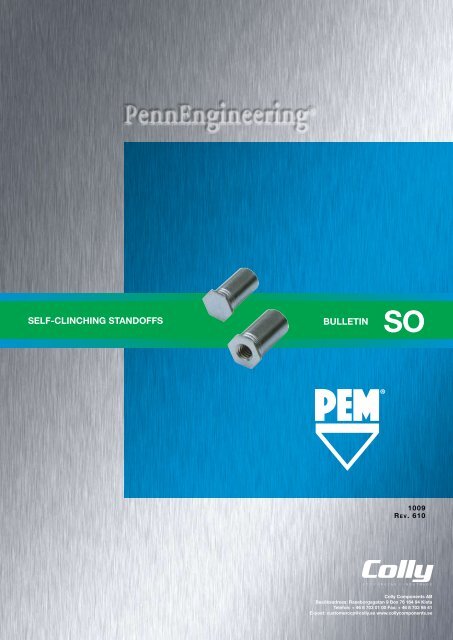
<strong>SELF</strong>-<strong>CLINCHING</strong> <strong>STANDOFFS</strong> <strong>BULLETIN</strong><br />
SO<br />
1009<br />
R e v . 610<br />
<strong>Colly</strong> <strong>Components</strong> AB<br />
Besöksadress: Raseborgsgatan 9 Box 76 164 94 Kista<br />
Telefon: + 46 8 703 01 00 Fax: + 46 8 703 98 41<br />
E-post: customerccp@colly.se www.collycomponents.se
<strong>SELF</strong>-<strong>CLINCHING</strong> <strong>STANDOFFS</strong><br />
<strong>SELF</strong>-<strong>CLINCHING</strong> <strong>STANDOFFS</strong><br />
These standoffs, which use the proven self-clinching design, install with a squeeze in properly sized round holes<br />
– and become permanently mounted in the thin sheet.<br />
PEM ® brand thru-hole threaded standoffs (Page 3) are installed with their heads flush with one surface of the<br />
mounting sheet. When blind-threaded types (Page 4) are used, outer sheet surfaces are not only flush, but closed<br />
as well. Unthreaded standoffs (Page 5) are also available for spacing multi-panel assemblies.<br />
Types SO4 and BSO4 standoffs (Pages 6 and 7) are for installation into stainless steel sheets as thin as 1.02<br />
mm.<br />
Types TSO, TSOS, and TSOA self-clinching threaded standoffs (Page 8) provide permanent threads in sheets<br />
as thin as 0.63 mm.<br />
PEM ® self-clinching standoffs are also available on special order in non-heat treated carbon steel as type SON<br />
(thru-hole threaded) or BSON (blind threaded).<br />
TYPES SO, SOA, AND SOS<br />
THRU-HOLE THREADED <strong>STANDOFFS</strong><br />
C<br />
B<br />
D<br />
L<br />
PART NUMBER DESIGNATION<br />
H<br />
METRIC<br />
Thread<br />
Code<br />
Min.<br />
Sheet<br />
Thickness<br />
Hole Size<br />
In Sheet<br />
+0.08<br />
GENERAL DIMENSIONAL DATA<br />
All dimensions are in millimeters.<br />
B<br />
Min. Dist.<br />
Counter- C H<br />
Hole C/<br />
Bore Dia. -0.13 Nom.<br />
±0.13 To Edge<br />
m3 1.02 4.22 3.2 4.2 4.8 6<br />
3.5m3 1.02 5.41 3.2 5.39 6.4 6.8<br />
M3.5 1.02 5.41 3.9 5.39 6.4 6.8<br />
m4 1.27 7.14 4.8 7.12 7.9 8<br />
m5 1.27 7.14 5.35 7.12 7.9 8<br />
Types DSO and DSOS standoffs (Page 9) are available for close-to-edge applications.<br />
SO S – M3 – 8 ZI<br />
Types SOAG and SOSG grounding standoffs (Page 9) are designed for clinching into steel or aluminum chassis<br />
while the “gripping teeth” on the opposite end of the standoff firmly contact mating PC board.<br />
If you require a standoff which we do not offer in this bulletin, please contact us. We will be happy to work with<br />
you to satisfy your special need. For other types of PEM ® brand standoffs and spacers see:<br />
Type<br />
Material<br />
Code<br />
Thread<br />
Size<br />
Code<br />
Length<br />
Code<br />
Finish<br />
Bulletin CH<br />
Bulletin K<br />
Bulletin SK<br />
Bulletin SSA<br />
PEM ® Concealed-head Standoffs.<br />
PEM ® Broaching and Surface Mount Standoffs for printed circuit boards.<br />
PEM ® KEYHOLE ® Standoffs.<br />
PEM ® brand SNAP-TOP ® Standoffs.<br />
THREAD SIZE AND LENGTH SELECTION DATA<br />
All dimensions are in millimeters.<br />
METRIC<br />
Thread<br />
Type<br />
Size x<br />
Thread<br />
Pitch<br />
Steel Stainless Aluminum Code<br />
Steel<br />
M3<br />
M3 x 0.5 SO SOS SOA<br />
3.5M3 (1)<br />
Length “L” +0.05 -0.13<br />
(Length Code in millimeters)<br />
3 4 6 8 10 12 14 16 18 N/A N/A N/A<br />
M3.5 x 0.6 SO SOS SOA M3.5 3 4 6 8 10 12 14 16 18 20 22 25<br />
m4 x 0.7 SO SOS SOA M4 3 4 6 8 10 12 14 16 18 20 22 25<br />
M5 x 0.8 SO SOS SOA M5 3 4 6 8 10 12 14 16 18 20 22 25<br />
D Dimension ±0.25 None 4 8 11<br />
Support This<br />
sheet<br />
(1) Standoffs with thread code 3.5M3 offer greater wall thickness for thread size M3.<br />
N/A - Not Available.<br />
Please contact your local PEM ® distributor for availability, minimum quantity, and pricing information.<br />
THRU-HOLE THREADS<br />
BLIND THREADS<br />
Always look for the<br />
“One or Two Groove”<br />
trademarks to be<br />
sure you are getting<br />
genuine PEM ® brand<br />
standoffs. On actual<br />
parts, location of<br />
grooves on barrel<br />
may be different than<br />
shown in photo.<br />
SO-2 PennEngineering • www.pemnet.com PennEngineering • www.pemnet.com SO-3
<strong>SELF</strong>-<strong>CLINCHING</strong> <strong>STANDOFFS</strong><br />
<strong>SELF</strong>-<strong>CLINCHING</strong> <strong>STANDOFFS</strong><br />
TYPES BSO, BSOA, AND BSOS<br />
BLIND THREADED <strong>STANDOFFS</strong><br />
C<br />
F<br />
L<br />
PART NUMBER DESIGNATION<br />
BSO S – M3 – 8 ZI<br />
H<br />
METRIC<br />
Thread<br />
Code<br />
GENERAL DIMENSIONAL DATA<br />
All dimensions are in millimeters.<br />
Min. Hole Size Min. Dist.<br />
C<br />
H<br />
Sheet In Sheet<br />
-0.13 Nom.<br />
Hole C/<br />
Thickness +0.08<br />
To Edge<br />
M3 1.02 4.22 4.2 4.8 6<br />
3.5M3 1.02 5.41 5.39 6.4 6.8<br />
M3.5 1.02 5.41 5.39 6.4 6.8<br />
M4 1.27 7.14 7.12 7.9 8<br />
M5 1.27 7.14 7.12 7.9 8<br />
TYPES SO, SOA, AND SOS<br />
THRU-HOLE UNTHREADED <strong>STANDOFFS</strong><br />
C<br />
B<br />
L<br />
PART NUMBER DESIGNATION<br />
SO S – 43.1 – 8 ZI<br />
H<br />
METRIC<br />
GENERAL DIMENSIONAL DATA<br />
All dimensions are in millimeters.<br />
Min. Hole Size Min. Dist.<br />
C<br />
H<br />
Thru-hole Sheet In Sheet<br />
Hole C/<br />
-0.13 Nom.<br />
Code Thickness +0.08<br />
To Edge<br />
43.1 1.02 4.22 4.2 4.8 6<br />
63.1 1.02 5.41 5.39 6.4 6.8<br />
63.6 1.02 5.41 5.39 6.4 6.8<br />
83.6 1.27 7.14 7.12 7.9 8<br />
84.1 1.27 7.14 7.12 7.9 8<br />
85.1 1.27 7.14 7.12 7.9 8<br />
PEM ® thru-hole, unthreaded standoffs<br />
are available on special order only.<br />
Type<br />
Material<br />
Code<br />
Thread<br />
Size<br />
Code<br />
Length<br />
Code<br />
Finish<br />
Type<br />
Material<br />
Code<br />
Thru-hole<br />
Code<br />
Length<br />
Code<br />
Finish<br />
THREAD SIZE AND LENGTH SELECTION DATA<br />
All dimensions are in millimeters.<br />
THRU-HOLE AND LENGTH SELECTION DATA<br />
All dimensions are in millimeters.<br />
METRIC<br />
Thread<br />
Type<br />
Size x<br />
Thread<br />
Steel Stainless Aluminum<br />
Pitch<br />
Code<br />
Steel<br />
M3 x 0.5 BSO BSOS BSOA<br />
M3<br />
3.5M3 (1)<br />
Length “L” +0.05 -0.13<br />
(Length Code in millimeters)<br />
6 8 10 12 14 16 18 20 22 25<br />
M3.5 x 0.6 BSO BSOS BSOA M3.5 6 8 10 12 14 16 18 20 22 25<br />
m4 x 0.7 BSO BSOS BSOA M4 6 8 10 12 14 16 18 20 22 25<br />
M5 x 0.8 BSO BSOS BSOA M5 6 8 10 12 14 16 18 20 22 25<br />
F Dimension Min. 3.2 4 5 6.5 9.5<br />
METRIC<br />
B<br />
Type<br />
Thru-hole<br />
Diameter<br />
Stainless<br />
+0.1 -0.08 Steel<br />
Steel<br />
3.1<br />
Aluminum<br />
s0 sos soa<br />
3.6 so sos soa<br />
Thru-hole<br />
Code<br />
43.1<br />
63.1 (1)<br />
63.6<br />
83.6 (1)<br />
Length “L” +0.05 -0.13<br />
(Length Code in millimeters)<br />
3 4 6 8 10 12 14 16 18 20<br />
3 4 6 8 10 12 14 16 18 20<br />
4.1 so sos soa 84.1 3 4 6 8 10 12 14 16 18 20<br />
5.1 SO SOS SOA 85.1 3 4 6 8 10 12 14 16 18 20<br />
(1) Standoffs with thread code 3.5M3 offer greater wall thickness for thread size M3.<br />
Please contact your local PEM ® distributor for availability, minimum quantity, and pricing information.<br />
(1) Standoffs with thread code 3.5M3 offer greater wall thickness for thread size M3.<br />
Please contact your local PEM ® distributor for availability, minimum quantity, and pricing information.<br />
SO-4 PennEngineering • www.pemnet.com PennEngineering • www.pemnet.com SO-5
<strong>SELF</strong>-<strong>CLINCHING</strong> <strong>STANDOFFS</strong><br />
<strong>SELF</strong>-<strong>CLINCHING</strong> <strong>STANDOFFS</strong><br />
TYPE SO4 THRU-HOLE THREADED<br />
<strong>STANDOFFS</strong> FOR INSTALLATION INTO<br />
STAINLESS STEEL SHEETS<br />
C<br />
B<br />
D<br />
METRIC<br />
Thread<br />
Code<br />
Min.<br />
Sheet<br />
Thickness<br />
Hole Size<br />
In Sheet<br />
+0.08<br />
GENERAL DIMENSIONAL DATA<br />
All dimensions are in millimeters.<br />
B<br />
Min. Dist.<br />
Counter- C H<br />
Hole C/<br />
Bore Dia. -0.13 Nom.<br />
±0.13 To Edge<br />
m3 1.02 4.22 3.25 4.2 4.8 6<br />
3.5m3 1.02 5.41 3.25 5.39 6.4 7.1<br />
M3.5 1.02 5.41 3.9 5.39 6.4 7.1<br />
m4 1.27 7.14 4.8 7.12 7.9 8.4<br />
m5 1.27 7.14 5.35 7.12 7.9 8.4<br />
TYPE BSO4 BLIND THREADED<br />
<strong>STANDOFFS</strong> FOR INSTALLATION INTO<br />
STAINLESS STEEL SHEETS<br />
C<br />
F<br />
METRIC<br />
Thread<br />
Code<br />
GENERAL DIMENSIONAL DATA<br />
All dimensions are in millimeters.<br />
Min. Hole Size Min. Dist.<br />
C<br />
H<br />
Sheet In Sheet<br />
-0.13 Nom.<br />
Hole C/<br />
Thickness +0.08<br />
To Edge<br />
M3 1.02 4.22 4.2 4.8 6<br />
3.5M3 1.02 5.41 5.39 6.4 7.1<br />
M3.5 1.02 5.41 5.39 6.4 7.1<br />
M4 1.27 7.14 7.12 7.9 8.4<br />
M5 1.27 7.14 7.12 7.9 8.4<br />
L<br />
H<br />
L<br />
H<br />
PART NUMBER DESIGNATION<br />
SO 4 – M3 – 8<br />
PART NUMBER DESIGNATION<br />
BSO 4 – M3 – 8<br />
Type<br />
Material<br />
Code<br />
Thread<br />
Size<br />
Code<br />
Length<br />
Code<br />
Type<br />
Material<br />
Code<br />
Thread<br />
Size<br />
Code<br />
Length<br />
Code<br />
THREAD SIZE AND LENGTH SELECTION DATA<br />
All dimensions are in millimeters.<br />
THREAD SIZE AND LENGTH SELECTION DATA<br />
All dimensions are in millimeters.<br />
Thread<br />
Size x<br />
Pitch<br />
Type<br />
Thread<br />
Code<br />
Length “L” +0.05 –0.13<br />
(Length Code in millimeters)<br />
Thread<br />
Size x<br />
Pitch<br />
Type<br />
Thread<br />
Code<br />
Length “L” +0.05 –0.13<br />
(Length Code in millimeters)<br />
METRIC<br />
M3 x 0.5 SO4<br />
M3<br />
3.5M3 (1) 3 4 6 8 10 12 14 16 18 N/A N/A N/A<br />
M3.5 x 0.6 SO4 M3.5 3 4 6 8 10 12 14 16 18 20 22 25<br />
m4 x 0.7 SO4 M4 3 4 6 8 10 12 14 16 18 20 22 25<br />
M5 x 0.8 SO4 M5 3 4 6 8 10 12 14 16 18 20 22 25<br />
D Dimension ±0.25 None 4 8 11<br />
METRIC<br />
M3 x 0.5<br />
bso4<br />
M3<br />
3.5M3 (1)<br />
6 8 10 12 14 16 18 20 22 25<br />
M3.5 x 0.6 BSO4 M3.5 6 8 10 12 14 16 18 20 22 25<br />
m4 x 0.7 bso4 M4 6 8 10 12 14 16 18 20 22 25<br />
M5 x 0.8 BSO4 M5 6 8 10 12 14 16 18 20 22 25<br />
F Dimension Min. 3.2 4 5 6.5 9.5<br />
(1) Standoffs with thread code 3.5M3 offer greater wall thickness for thread size M3.<br />
N/A Not Available.<br />
Please contact your local PEM ® distributor for availability, minimum quantity, and pricing information.<br />
(1) Standoffs with thread code 3.5M3 offer greater wall thickness for thread size M3.<br />
Please contact your local PEM ® distributor for availability, minimum quantity, and pricing information.<br />
SO-6 PennEngineering • www.pemnet.com PennEngineering • www.pemnet.com SO-7
<strong>SELF</strong>-<strong>CLINCHING</strong> <strong>STANDOFFS</strong><br />
<strong>SELF</strong>-<strong>CLINCHING</strong> <strong>STANDOFFS</strong><br />
TYPES TSO, TSOA AND TSOS THREADED <strong>STANDOFFS</strong><br />
FOR SHEETS AS THIN AS .025”/0.63mm<br />
GENERAL DIMENSIONAL DATA<br />
All dimensions are in millimeters.<br />
TYPES DSO AND DSOS THREADED <strong>STANDOFFS</strong><br />
FOR CLOSE-TO-EDGE APPLICATIONS<br />
C<br />
Style #1<br />
L<br />
D<br />
Style #2<br />
(Screw may not pass thru unthreaded end)<br />
C<br />
D<br />
Style #3 (Blind)<br />
L<br />
METRIC<br />
D<br />
Thread<br />
Min. Hole Size<br />
Min. Dist.<br />
C Min. H<br />
Code<br />
Sheet In Sheet<br />
Hole C/<br />
-0.13 Thread Nom.<br />
Thickness +0.08<br />
Depth<br />
To Edge<br />
M25 0.63 4.22 4.2<br />
4.8 5.8<br />
5.2<br />
6M25 0.63 5.41 5.39 6.4 7.1<br />
M3 0.63 4.22 4.2<br />
4.8 5.8<br />
6.2<br />
6M3 0.63 5.41 5.39 6.4 7.1<br />
M35 0.63 5.41 5.39 7 6.4 7.1<br />
All dimensions are in millimeters.<br />
PART NUMBER DESIGNATION<br />
DSO S – M3 – 7 ZI<br />
Type<br />
Material<br />
Code<br />
Thread<br />
Size<br />
Code<br />
Length<br />
Code<br />
Finish<br />
(if applicable)<br />
C<br />
L<br />
H<br />
C<br />
L<br />
H<br />
METRIC<br />
Thread Type Hole Size<br />
C<br />
L (1) Min. Dist.<br />
Size x Stainless Thread Length Sheet In Sheet<br />
Steel<br />
Max.<br />
H +0.05 Hole C/<br />
Pitch Steel Code Code Thickness +0.08 Nom. -0.13 To Edge<br />
6.35<br />
6.35<br />
M3 x 0.5 DSOS DSO M3<br />
0.94 - 6.35 4.22 4.2 4.92<br />
3.2<br />
7 7<br />
(1) Available in other lengths on special order.<br />
THREAD SIZE AND LENGTH SELECTION DATA<br />
All dimensions are in millimeters.<br />
Please contact your local PEM ® distributor for availability, minimum quantity, and pricing information.<br />
METRIC<br />
Thread<br />
Size x<br />
Pitch<br />
Steel<br />
M2.5 x 0.45 TSO Tsos Tsoa<br />
M3 x 0.5 Tso Tsos Tsoa<br />
Type Length “L” ±0.08<br />
For other lengths / thread depth data see chart below.<br />
Thread<br />
Stainless<br />
Steel<br />
Aluminum Code 2.00 3.00 4.00 6.00 8.00 10.00 12.00 14.00<br />
Length Code (Length “L” without decimal point)<br />
16.00 18.00 19.00<br />
M25<br />
6M25 (4)<br />
M3<br />
6M3 (4)<br />
200 (1) 300 (1) 400 (1) 600 (1) 800 (2) 1000 (3) 1200 (3) 1400 (3) 1600 (3) 1800 (3) 1900 (3)<br />
200 (1) 300 (1) 400 (1) 600 (1) 800 (2) 1000 (2) 1200 (3) 1400 (3) 1600 (3) 1800 (3) 1900 (3)<br />
M3.5 x 0.6 Tso Tsos TsoA M35 N/A 300 (1) 400 (1) 600 (1) 800 (1) 1000 (2) 1200 (2) 1400 (3) 1600 (3) 1800 (3) 1900 (3)<br />
(1) Style #1. (2) Style #2. (3) Style #3. (N/A) Not Available<br />
(4) Standoffs with thread code 6M3 offer greater wall thickness for thread size M3.<br />
Please contact your local PEM ® distributor for availability, minimum quantity, and pricing information.<br />
TYPES SOSG AND SOAG GROUNDING <strong>STANDOFFS</strong><br />
PC Board<br />
or plastic<br />
PART NUMBER DESIGNATION<br />
SOSG – 3.5M3 – 10<br />
C<br />
Gripping Teeth<br />
LENGTH/STYLE DATA<br />
All dimensions are in millimeters.<br />
(Length can be specified in .02mm increments.)<br />
METRIC<br />
Thread Length “L” Length “L” Length “L”<br />
Code (Style #1) (Style #2) (Style #3)<br />
M25<br />
6M25<br />
2.00 - 6.30 6.32 - 9.50 9.52 - 19.00<br />
M3<br />
6M3<br />
2.00 - 7.50 7.52 - 11.00 11.02 - 19.00<br />
M35 3.00 - 8.80 8.82 - 12.80 12.82 - 19.00<br />
PART NUMBER DESIGNATION<br />
TSO S – M3 – 300<br />
Type<br />
Material<br />
Code<br />
Thread<br />
Size<br />
Code<br />
Length<br />
Code<br />
ZI<br />
Finish<br />
(if applicable)<br />
METRIC<br />
Metal<br />
All dimensions are in millimeters.<br />
Type and Material<br />
SOSG = stainless steel<br />
SOAG = aluminum<br />
Thread<br />
Code<br />
Thread Type<br />
Length “L” +0.25<br />
Min. Hole D<br />
Size x<br />
Thread (Length Code is in millimeters) Sheet Size In C H P Min. Dist.<br />
Anvil<br />
Pitch<br />
Stainless<br />
Code<br />
(2)<br />
Thick- Sheet –0.13 ±0.25 Nom.<br />
HoleC/L<br />
Hole<br />
Steel Aluminum ness +0.08<br />
To Edge<br />
+0.08<br />
m3 x 0.5 sosg soag 3.5m3 3 ns 4 ns 6 8 10 12 1 5.4 5.39 6.4 0.76 6.8 5.5<br />
Length<br />
Code<br />
(2) For special lengths greater than .500” / 12 mm, Types SOSG and SOAG are blind threaded.<br />
H<br />
P<br />
L<br />
SO-8 PennEngineering • www.pemnet.com PennEngineering • www.pemnet.com SO-9
<strong>SELF</strong>-<strong>CLINCHING</strong> <strong>STANDOFFS</strong><br />
<strong>SELF</strong>-<strong>CLINCHING</strong> <strong>STANDOFFS</strong><br />
MATERIAL AND FINISH SPECIFICATIONS<br />
Threads (1) Fastener Materials Standard Finishes For Use In Sheet Hardness: (3)<br />
Internal, ASME Heat- Non-heat 300 400 Zinc Plated Passivated<br />
B1.1 2B treated Treated Series Series 5µm, and/or Tested HRB 88 / HRB 80 / HRB 70 / HRB 60 / HRB 50 /<br />
Type ASME Carbon Carbon Aluminum Stainless Stainless Colorless Per ASTM No HB 176 HB 150 HB 125 HB 107 HB 82<br />
B1.13M, 6H Steel Steel Steel Steel (2) A380 Finish or Less or Less or Less or Less or Less<br />
SO • • • •<br />
SOA • • • •<br />
SOS • • • •<br />
SO4 • • • •<br />
BSO • • • •<br />
BSOA • • • •<br />
BSOS • • • •<br />
BSO4 • • • •<br />
TSO • • • •<br />
TSOS • • • •<br />
TSOA • • • •<br />
DSO • • • •<br />
DSOS • • • •<br />
SOAG • • • •<br />
SOSG • • • •<br />
Part Number Codes For Finishes ZI None None<br />
(1) Where applicable.<br />
(2) See PEM Technical Support section of our web site for related plating standards and specifications.<br />
(3) HRB - Hardness Rockwell “B” Scale. HB - Hardness Brinell.<br />
INSTALLATION<br />
PUNCH<br />
INSTALLATION<br />
TYPES DSO, DSOS, SOAG AND SOSG<br />
1. Prepare properly sized mounting hole in sheet. Do not perform any secondary operations such as deburring.<br />
2. Insert fastener through mounting hole and into anvil as shown in drawing.<br />
3. With punch and anvil surfaces parallel, apply only enough squeezing force to embed the standoff’s head flush in<br />
the sheet.<br />
7 mm<br />
Min.<br />
Types DSO and DSOS<br />
PUNCH<br />
ANVIL<br />
4.3mm -<br />
4.4mm<br />
”L” Min.<br />
Types SOAG and SOSG<br />
PUNCH<br />
D<br />
+.003<br />
–.000<br />
ANVIL<br />
PEMSERTER ® PRESSES<br />
For best results we recommend using a<br />
PEMSERTER ® press for either manual or<br />
automatic installation of PEM standoffs. For<br />
more information on our line of presses call<br />
1-800-523-5321, or check our web site.<br />
TYPES SO, SOA, SOS, SO4, BSO, BSOA, BSOS AND BSO4<br />
PERFORMANCE DATA (1)<br />
1. Prepare properly sized mounting hole in sheet. Do not perform any<br />
secondary operation such as deburring.<br />
2. Insert standoff through mounting hole of sheet and into anvil as<br />
shown in drawing.<br />
3. With punch and anvil surfaces parallel, apply only enough<br />
squeezing force to embed the standoff’s head flush in the sheet.<br />
Drawing at right shows suggested tooling for applying these forces.<br />
TYPES TSO, TSOA AND TSOS<br />
1. Prepare properly sized mounting hole in sheet. Do not perform<br />
any secondary operation such as deburring.<br />
2. Insert standoff through mounting hole of sheet and into anvil as<br />
shown in drawing.<br />
3. With punch and anvil surfaces parallel, apply only enough<br />
squeezing force to embed the standoff’s head flush in the<br />
sheet. Drawing at right shows required installation anvil for<br />
sheet thickness of 0.63 to 0.81mm.<br />
A chamfered anvil is not required for sheets over 0.81mm.<br />
”L” Min.<br />
REQUIRED INSTALLATION ANVIL<br />
FOR SHEETS BELOW 0.81MM<br />
120˚<br />
B<br />
C<br />
+0.1 mm<br />
+0.18 mm<br />
”L” Min.<br />
PUNCH<br />
ANVIL<br />
ANVIL<br />
TYPES SO, SOA, SOS, BSO, BSOA AND BSOS<br />
METRIC<br />
Thread<br />
Code<br />
Max. Rec.<br />
Test Sheet Material<br />
Tightening<br />
Standoff<br />
Torque For<br />
1.5 mm 5052-H34 Aluminum (2) 1.5 mm Cold-rolled Steel (2)<br />
Material<br />
Mating Screw Installation Pushout Torque-out Pull-thru Installation Pushout Torque-out Pull-thru<br />
(N•m) (kN) (N) (N•m) (N) (kN) (N) (N•m) (N)<br />
Steel 0.55 4.9 710 1.24 1245 9.8 1000 2.15 1465<br />
M3 Stainless Steel 0.44 4.9 710 1.24 996 9.8 1000 2.15 1172<br />
Aluminum 0.33 4.9 710 1.24 747 (3) (3) (3) (3)<br />
Steel 0.55 7.6 1330 1.24 1245 14.7 1860 2.15 1465<br />
3.5M3 Stainless Steel 0.44 7.6 1330 1.24 996 14.7 1860 2.15 1172<br />
Aluminum 0.33 7.6 1330 1.24 747 (3) (3) (3) (3)<br />
Steel 0.91 7.6 1330 2.82 1375 14.7 1860 3.95 1690<br />
M3.5 Stainless Steel 0.73 7.6 1330 2.82 1100 14.7 1860 3.95 1352<br />
Aluminum 0.55 7.6 1330 2.82 825 (3) (3) (3) (3)<br />
Steel 2, 3.6 10.7 1780 5.08 2575 17.8 2490 8.47 3110<br />
M4, M5 Stainless Steel 1.6, 2.88 10.7 1780 5.08 2060 17.8 2490 8.47 2488<br />
Aluminum 1.2, 2.16 10.7 1780 5.08 1545 (3) (3) (3) (3)<br />
(1) The values reported are averages when all installation specifications and procedures are followed. Variations in mounting hole<br />
size, sheet material and installation procedure will affect this data. Performance testing of this product in your application is<br />
recommended. We will be happy to provide samples for this purpose.<br />
(2) Standoffs installed in sheets thinner than1.5mm and greater than the specified minimum sheet thickness will have pull-thru, pushout, and torqueout<br />
values approximately 80% of tabulated values.<br />
(3) Not recommended.<br />
All dimensions are in millimeters.<br />
Standoff “C”<br />
Anvil Dimensions<br />
Dimensions<br />
A<br />
B<br />
A<br />
4.19 4.24 - 4.32 4.75 - 4.93<br />
5.39 5.41 - 5.49 6.35 - 6.53<br />
SO-10 PennEngineering • www.pemnet.com PennEngineering • www.pemnet.com SO-11
<strong>SELF</strong>-<strong>CLINCHING</strong> <strong>STANDOFFS</strong><br />
PERFORMANCE DATA (1)<br />
TYPES SO4 AND BSO4<br />
METRIC<br />
Thread<br />
Code<br />
Max. Rec.<br />
Test Sheet Material<br />
Tightening<br />
Torque For<br />
1.3 mm 300 Series Stainless Steel<br />
Mating Screw Installation Pushout Torque-out Pull-thru<br />
(N•m) (kN) (N) (N•m) (N)<br />
M3 0.55 24.5 1493 2.36 2650<br />
3.5M3 0.55 42.3 2877 2.36 3025<br />
M3.5 0.91 42.3 2877 3.06 3025<br />
M4 2 46.7 4003 6.34 6458<br />
M5 3.6 46.7 4003 8.89 6226<br />
TYPES TSO, TSOA AND TSOS<br />
Test Sheet Material<br />
Standoff “C” Standoff 0.64 mm 5052-H34 Aluminum 0.64 mm Cold-rolled Steel<br />
Dimension<br />
Material<br />
Installation Pushout Torque-out Installation Pushout Torque-out<br />
(kN) (N) (N•m) (kN) (N) (N•m)<br />
Steel 6.7 311 0.68 8.9 445 1<br />
4.19 mm Stainless Steel 6.7 311 0.68 8.9 445 1<br />
Aluminum 6.7 311 0.68 — — —<br />
Steel 8 400 1.24 11.1 667 1.7<br />
5.38 mm Stainless Steel 8 400 1.24 11.1 667 1.7<br />
Aluminum 8 400 1.24 — — —<br />
TYPES DSO AND DSOS<br />
METRIC<br />
Thread<br />
Code<br />
Max. Rec.<br />
Test Sheet Material<br />
Tightening<br />
Torque For<br />
1 mm 5052-H34 Aluminum 1 mm Cold-rolled Steel<br />
Mating Screw Installation Pushout Torque-out Installation Pushout Torque-out<br />
(N•m) (kN) (N) (N•m) (kN) (N) (N•m)<br />
M3 0.44 4.5 223 1.1 5.8 334 1.1<br />
TYPES SOAG AND SOSG<br />
METRIC<br />
Thread Test Sheet Thickness and Installation Pushout Torque-out<br />
Code Test Sheet Material (kN) (N) (2) (N•m)<br />
3.5M3 1.6mm 5052-h34 Aluminum 7.6 1330 2.82<br />
(1) The values reported are averages when all installation specifications and procedures are followed. Variations in mounting hole<br />
size, sheet material and installation procedure will affect this data. Performance testing of this product in your application is<br />
recommended. We will be happy to provide samples for this purpose.<br />
(2) These are typical values for parts installed in drilled mounting holes. Punched mounting holes yield values approximately 15% less.<br />
RoHS compliance information can be found on our website.<br />
© 2010 PennEngineering.<br />
Specifications subject to change without notice.<br />
Check our website for the most current version of this bulletin.<br />
SO-12


