CERN PS/PP Note 2002-104 - Klaus Hanke's Home Page - CERN
CERN PS/PP Note 2002-104 - Klaus Hanke's Home Page - CERN
CERN PS/PP Note 2002-104 - Klaus Hanke's Home Page - CERN

You also want an ePaper? Increase the reach of your titles
YUMPU automatically turns print PDFs into web optimized ePapers that Google loves.
EUROPEAN ORGANIZATION FOR NUCLEAR RESEARCH<br />
<strong>CERN</strong> <strong>PS</strong>/<strong>PP</strong> <strong>Note</strong> <strong>2002</strong>-<strong>104</strong><br />
Possible Injection Schemes for the <strong>CERN</strong> Laser Ion Source into Linac III<br />
J.F. Amand, K.Hanke, A. Lombardi<br />
Abstract<br />
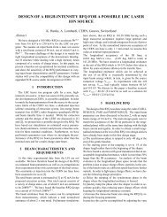
A laser ion source is presently under study at <strong>CERN</strong> in the frame of the LHC heavy ion<br />
program. This source is supposed to deliver a high-current beam of 208Pb 25+ via LEBT,<br />
RFQ and a dedicated injection line into the <strong>CERN</strong> ion linac (Linac III). While the design<br />
of LEBT and RFQ have been addressed in previous notes, we present in this note possible<br />
injection lines from the RFQ to the linac.<br />
Geneva, Switzerland<br />
June 5, <strong>2002</strong>
1 Introduction<br />
A possible source candidate for the LHC ion program is a Laser Ion Source (LIS),<br />
presently under study at <strong>CERN</strong>. We have studied for the example of this source possible extraction<br />
systems [1], possible low-energy beam transport lines (LEBT) [2] as well as a radiofrequency<br />
quadrupole (RFQ) [3]. In this note, we address possible injection schemes from the<br />
RFQ into the <strong>CERN</strong> ion linac (Linac III).<br />
We have studied a scheme, where a new ion source (here: LIS) injects into Linac III while<br />
keeping the possibility to inject beam from the present ECR source. We present two different<br />
scenarios: in the first case, the existing ECR source injects into Linac III through a modified<br />
MEBT which houses an additional dipole. The LIS injects via an achromatic line. In the second<br />
case, the LIS injects via the straight line, while the ECR source injects via the bent line.<br />
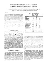
2 Input Beam Parameters<br />
We have used for the simulation of the injection line for the LIS input beam parameters<br />
which have been obtained from a simulation of a dedicated LIS RFQ [3]. For the beam coming<br />
from the present ECR source, we have used the beam parameters at the exit of the existing RFQ<br />
installed in Linac III. Table 1 summarises the beam parameters at the exit of both RFQs, which<br />
have been used as input for the simulation of the injection lines.<br />
new LIS RFQ design existing Linac III RFQ<br />
α x -1.75 1.54<br />
β x [m/rad] 0.16 0.22<br />
ε x (r.m.s., norm.) [mm mrad] 0.17 2 0.082 2<br />
α y 1.52 -1.46<br />
β y [m/rad] 0.14 0.19<br />
ε y (r.m.s., norm.) [mm mrad] 0.17 2 0.08 2<br />
α l -0.23 -0.037<br />
β l [deg/MeV] 28.24 57.61<br />
ε l (r.m.s.) [MeV deg/u] 0.016 0.0067<br />
2) 1/6 of total emittance for waterbag distribution.<br />
Table 1: Output beam parameters of new LIS RFQ and existing Linac III RFQ.<br />
3 Injection Lines into Linac III<br />
We have designed transfer lines from the RFQ to Linac III which allow to inject beam<br />
either from the present ECR source or from the LIS into the linac. Two possibilities of such a<br />
switch yard have been studied:<br />
1.) The present ECR source stays in its place. The existing MEBT of Linac III is modified such<br />
that it can house an additional dipole. The beam from the LIS RFQ is injected via an achromatic<br />
line.<br />
2.) The LIS injects via a straight line into Linac III and the present ECR source injects via an<br />
achromatic line.<br />
3.1 Scenario 1: LIS Injection via Achromatic Line; ECR Injection via Straight Line<br />
3.1.1 LIS Injection via Achromatic Line<br />
The bent line, via which the beam from the LIS RFQ is injected into Linac III, is supposed<br />
to be achromatic. Further design goals were to match the line to the IH acceptance parameters<br />
1
and to limit transverse and longitudinal emittance growth.<br />
In its simplest form, an achromatic line consists of two dipole magnets with two quadrupole<br />
magnets in between (see e.g. [4]). In our case, where the beam is space-charge dominated,<br />
we use two triplets between the dipoles in order to transport the beam without unacceptable<br />
transverse and longitudinal emittance growth. The longitudinal matching of this line to the<br />
IH acceptance is done by adjusting the voltage of the two buncher cavities before and after<br />
the bending magnets. Figure 1 shows the design of the achromatic line as simulated with the<br />
envelope code TRACE.<br />
From the simulation program TRACE we obtain the matched values of the quadrupoles and<br />
bunchers, but it does not take into consideration non-linearities. To evaluate the beam transport<br />
from the RFQ to the IH, we have used the multi-particle tracking code PATH. The figure of<br />
merit is the injection efficiency into the IH which is characterised by the following acceptance:<br />
in the horizontal plane α = 1.69, β = 0.94 mm/mrad, ε =1π mm mrad (norm.);<br />
in the vertical plane α = 0.47, β = 0.55 mm/mrad, ε =1π mm mrad (norm.);<br />
in the longitudinal plane α = -1.28, β = 0.23 mm/mrad, ε = 18.72 deg MeV.<br />
Figures 2, 3 and 4 show the horizontal, vertical and longitudinal phase space at the exit of the<br />
achromatic line. We find an injection efficiency into the IH of 87.6% in the horizontal plane,<br />
90.0% in the vertical plane and 65.9% in the longitudinal plane. This yields an overall injection<br />
efficiency of 54.7%. The remanent dispersion at the exit of the line is 15 cm.<br />
3.1.2 ECR Injection via Straight Line<br />
The existing MEBT of Linac III needs to be modified to house an additional dipole which<br />
is needed to inject the LIS beam. We have used the four quadrupoles from the existing line, but<br />
changed their positions and settings. The aperture of the first two quadrupoles is 20 mm, while<br />
for quadrupoles 3 and 4 it is 16 mm. Figure 5 shows the original and the modified MEBT of<br />
Linac III as simulated with TRACE. In the present MEBT, the aperture of the second quadrupole<br />
limits the transverse acceptance to 48.9 mm mrad. For the modified MEBT, we find an acceptance<br />
of 33.9 mm mrad. This would mean a reduction of about 30%. Possible ways to improve<br />
this are to increase the aperture of quadrupole 3 to 22 mm, which would yield the same acceptance<br />
as for the present MEBT. Alternatively, one can permute quadrupoles 1 and 3. In this case<br />
the acceptance is limited by the second quadrupole to 40 mm mrad, which means a reduction<br />
of the transverse acceptance by 18% with respect to the present MEBT.<br />
2
Figure 1: Achromatic line for LIS beam as simulated with TRACE.<br />
25<br />
20<br />
15<br />
10<br />
5<br />
x' [mrad]<br />
0<br />
-10 -8 -6 -4 -2 0 2 4 6 8 10<br />
-5<br />
-10<br />
-15<br />
-20<br />
-25<br />
x [mm]<br />
Figure 2: Horizontal phase space at the exit of the achromatic line as simulated with PATH. The<br />
solid ellipse indicates the acceptance of the IH, in which 87.6% of the particles are found.<br />
3
15<br />
10<br />
5<br />
y' [mrad]<br />
-10 -8 -6 -4 -2 0 2 4 6 8<br />
0<br />
-5<br />
-10<br />
-15<br />
y [mm]<br />
Figure 3: Vertical phase space at the exit of the achromatic line as simulated with PATH. The<br />
solid ellipse indicates the acceptance of the IH, in which 90.0% of the particles are found.<br />
2000<br />
1500<br />
1000<br />
500<br />
∆W [keV]<br />
0<br />
-100 -80 -60 -40 -20 0 20 40 60 80 100<br />
-500<br />
-1000<br />
-1500<br />
-2000<br />
Phi [deg]<br />
Figure 4: Longitudinal phase space at the exit of the achromatic line as simulated with PATH.<br />
The solid ellipse indicates the acceptance of the IH, in which 65.9% of the particles are found.<br />
4
Figure 5: Original (upper Figure) and modified MEBT (lower Figure) of Linac III as simulated<br />
with TRACE.<br />
5
3.2 Scenario 2:<br />
LIS Injection via Straight Line; ECR Injection via Achromatic Line<br />
3.2.1 LIS Injection via Straight Line<br />
As an alternative to the scheme reported in Section 3.1, we have studied a scheme where<br />
the beam from the LIS RFQ is injected via a straight line directly into Linac III. The present<br />
ECR source is in this scenario moved and injects via a bent, achromatic line. Figure 6 shows<br />
the straight injection line for the LIS as simulated with TRACE.<br />
Figure 6: LIS injection via straight line as simulated with TRACE.<br />
Again, this line was simulated using the tracking code PATH. Figures 7, 8 and 9 show the<br />
horizontal, vertical and longitudinal phase space at the exit of the straight line. We find an<br />
injection efficiency into the IH of 91.3% in the horizontal plane, 94.3% in the vertical plane and<br />
74.3% in the longitudinal plane. This yields an overall injection efficiency of 67.2%. This value<br />
is higher than in the case of the bent line because of the total absence of dispersion.<br />
6
25<br />
20<br />
15<br />
10<br />
x' [mrad]<br />
5<br />
0<br />
-15 -10 -5 0 5 10 15<br />
-5<br />
-10<br />
-15<br />
-20<br />
x [mm]<br />
Figure 7: Horizontal phase space at the exit of the straight line as simulated with PATH. The<br />
solid ellipse indicates the acceptance of the IH, in which 91.3% of the particles are found.<br />
15<br />
10<br />
5<br />
y' [mrad]<br />
0<br />
-10 -8 -6 -4 -2 0 2 4 6 8 10<br />
-5<br />
-10<br />
-15<br />
y [mm]<br />
Figure 8: Vertical phase space at the exit of the achromatic line as simulated with PATH. The<br />
solid ellipse indicates the acceptance of the IH, in which 94.3% of the particles are found.<br />
2000<br />
1500<br />
1000<br />
500<br />
∆W [keV]<br />
0<br />
-150 -100 -50 0 50 100 150<br />
-500<br />
-1000<br />
-1500<br />
-2000<br />
Phi [deg]<br />
Figure 9: Longitudinal phase space at the exit of the straight line as simulated with PATH. The<br />
solid ellipse indicates the acceptance of the IH, in which 74.3% of the particles are found.<br />
7
3.2.2 ECR Injection via Achromatic Line<br />
The ECR source injects via an achromatic line into Linac III. The lay-out of the line is<br />
the same as discussed in Section 3.1.1. Figure 10 shows the simulation of the line with TRACE.<br />
Figure 10: ECR source injecting via achromatic line. Simulation with TRACE.<br />
4 Conclusions<br />
We have studied two possible injection schemes for the beam coming from the <strong>CERN</strong><br />
laser ion source into the Linac III. The simulations are based on a simulation of the LIS RFQ,<br />
which, in turn, is based on assumed beam parameters from the source. A final design of RFQ<br />
and injection lines can only be made once the source parameters are experimentally known.<br />
So far we can conclude, that a direct injection of the high-current LIS beam into the IH is<br />
preferred with respect to an injection via a bent line. The main limitation for the injection<br />
efficiency is found in the longitudinal plane. The longitudinal matching could be improved by<br />
moving the position of the second buncher with respect to the IH entry plane. For the simulations<br />
reported here, the position of this buncher has been left as it is in the present Linac III MEBT.<br />
References<br />
[1] R. Scrivens, Extraction Geometry for the Future LIS Plasma, <strong>CERN</strong> <strong>PS</strong>/<strong>PP</strong> <strong>Note</strong> 2001-003<br />
(2001).<br />
[2] K. Hanke, S. Heising, R. Scrivens, Comparison of the Beam Dynamic Solutions for Low<br />
Energy Beam Transport Systems for a Laser Ion Source at <strong>CERN</strong>, <strong>CERN</strong> <strong>PS</strong>/<strong>PP</strong> <strong>Note</strong> 2001-<br />
004 (2001).<br />
[3] K. Hanke, A. Lombardi, Preliminary Design of an RFQ for the <strong>CERN</strong> Laser Ion Source,<br />
<strong>CERN</strong> <strong>PS</strong>/<strong>PP</strong> <strong>Note</strong> 067 (<strong>2002</strong>).<br />
[4] H. Wiedemann, Particle Accelerator Physics, Vol. I, Springer (1993).<br />
[5] Tracking Code PATH, <strong>CERN</strong> version, documentation in preparation.<br />
8
Distribution List<br />
J.F. Amand <strong>PS</strong>/<strong>PP</strong><br />
J.G. Correia <strong>PS</strong>/<strong>PP</strong><br />
K. Hanke <strong>PS</strong>/<strong>PP</strong><br />
H. Kugler <strong>PS</strong>/<strong>PP</strong><br />
A. Lombardi <strong>PS</strong>/<strong>PP</strong><br />
K. Schindl <strong>PS</strong>/<strong>PP</strong><br />
R. Scrivens <strong>PS</strong>/<strong>PP</strong><br />
9