conf. proc. LINAC2002 - Klaus Hanke's Home Page - CERN
conf. proc. LINAC2002 - Klaus Hanke's Home Page - CERN
conf. proc. LINAC2002 - Klaus Hanke's Home Page - CERN
- No tags were found...

Create successful ePaper yourself
Turn your PDF publications into a flip-book with our unique Google optimized e-Paper software.
PUBLIC DISCLOSURETitle of the Company:Türk Ekonomi Bankası A.Ş.Address of the Company: Meclis-i Mebusan Cad. 57, 34427, Fındıklı- İSTANBULTelephone and Fax Number : (0212) 251 21 21 - (0216) 636 36 36Telephone and Fax Number of: (0212) 251 21 21 - (0216) 636 36 36investor/shareholder relations unit of theCompanyDate : 23 February 2011SubjectShare transfers following the merger of Fortis Bank A.Ş.and our Bank.Explanation :In the Board of Directors meeting of TEB Mali Yatırımlar A.Ş. (“Company”), one of the shareholdersof our Bank, it has been resolved that capital of the Company be increased from TL 500,000,000 to TL590,863,380; title of the Company be amended as TEB Holding A.Ş. and the general assembly beinvited to extraordinary meeting following the approvals from the regulatory authorities in order todiscuss the other amendments to the articles of association.As a result of the intended capital increase, TEB Mali Yatırımlar A.Ş. (TEB Holding A.Ş.) shares,held by BNP Paribas Fortis Yatırımlar Holding A.Ş. will be increased from 50% to 57,28% and theshareholding ratio of Colakoglu Group will be decreased from 50% to 42,72%. However, as declaredin the public disclosure dated 3 June 2010 and following disclosures with regard to the merger:(i)In order to maintain TEB Mali Yatırımlar A.Ş. (TEB Holding A.Ş.) as the mainshareholder in Türk Ekonomi Bankası A.Ş. (“TEB”) following the merger, share transferagreements have been signed on 23 February 2011 for the transfer of 12,72% of TEBshares, held by Fortis Bank SA/NV and 0,238% of TEB shares held by Çolakoğlu Groupto TEB Mali Yatırımlar A.Ş.As a result of the transactions explained above, TEB Mali Yatırımlar A.Ş.’s (TEB HoldingA.Ş.) shareholding ratio in TEB.will be increased to 55%.Another share transfer agreement has been signed on 23 February 2011 for the transfer ofTürk Ekonomi Bankası A.Ş. shares from Fortis Bank SA/NV to BNPP Yatırımlar HoldingA.Ş. and BNP Paribas Fortis Yatırımlar Holding A.Ş. following the approvals from theregulatory authorities, as further described in the table below:
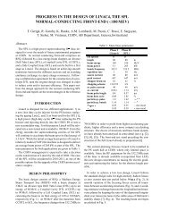
modulation in the first part of the RFQ, where the longitudinalemittance is formed. We find an RFQ withgood transmission (97.5%) and a longitudinal emittance ofε l = 0.015 MeV deg/u r.m.s. (0.075 MeV deg/u total). Thisis 20% below the IH acceptance and hence leaves somemargin for blow-up in the injection lines. The transverseemittance is essentially unchanged. The vane voltage is90 kV and the length of the RFQ is 396 cm. The radiusof curvature of the vane tips was chosen to ρ/r 0 =0.65 inorder to reduce the maximum electric field. The main RFQparameters are listed in Table 1. Figure 1 shows the inputand output beam as computed with PARMTEQM andFig. 2 shows the evolution of beam parameters versus cellnumber in the RFQ.design ion 208Pb 25+current [mA] 10.0input energy [keV/u] 9.6output energy [keV/u] 250.0design emittance (tot., norm) [mm mrad] 1.0frequency [MHz] 101.28vane voltage [kV] 90.0max. electric field [MV/m] 26.0RFQ length [cm] 396number of cells 310power loss (for 60 kΩm) [kW] 540minimum aperture [cm] 0.333max. modulation factor 1.7transmission 1 [%] 97.5mid-cell radial aperture r o [cm] 0.458vane tip radius of curvature ρ/r o 0.651) For 1 π mm mrad input emittance (tot., norm.) and 10 mA, simulationwith 1000 particles.Table 1: Important parameters of baseline RFQ.Figure 2: Evolution of beam parameters versus cell numberas simulated with PARMTEQM. The lines indicates thephysical aperture in the upper two plots and the separatrixin the lower two plots.4 PARAMETER SCAN4.1 Beam EnergyThe input beam energy is a trade-off between extractedbeam current and achievable longitudinal emittance. Thehigher the input beam energy, the longer the RFQ and themore difficult it is to form a small longitudinal emittance.We have found a solution for V extr =80 kV. However, wehave investigated the possibility of designing an RFQ forV extr =100 kV (12.0 keV/u). We find a solution with alength of 435 cm (390 cells) and an output longitudinalemittance of ε l =0.016 MeV deg/u, which is 12% belowthe IH acceptance. However, this solution is unstable andalready minor variations of the modulation lead to unacceptableblow-up of the longitudinal emittance. We willtherefore in the following sections only consider in moredetail the reference case with V extr =80 kV.4.2 Energy SpreadThe simulations shown in Section 3 have been done withzero energy spread. As from the real source we expect asignificant energy spread, we have changed in the simulationthe input beam accordingly. Figure 3 shows transmissionand longitudinal emittance versus energy spreadfor the baseline RFQ. It can be seen that the transmissiondrops down to about 85% for 10% energy spread. More important,the longitudinal emittance increases significantlyalready for small values of ∆E.Figure 1: Input (upper plots) and output (lower plots) beamof the RFQ as simulated with PARMTEQM.4.3 Beam EmittanceFigure 4 shows transmission versus input transverseemittance. For values smaller than the nominal value of1 π mm mrad, the transmission is constant around 98%.
9896transmission [%]9492908886840 0.2 0.4 0.6 0.8 1 1.2 1.4 1.6 1.8 2rms long. emit. [MeV deg/u]0.0450.040.0350.030.0250.020.0150 0.2 0.4 0.6 0.8 1 1.2 1.4 1.6 1.8 2total energy spread [keV/u]Figure 3: Transmission (upper plot) and longitudinal emittance(lower plot) versus input energy spread. The dashedline represents the longitudinal acceptance of the IH.No higher transmission can be achieved, as the losses havetheir origin in the longitudinal plane. For higher input emittancethan the nominal one, the transmission drops downuntil about 87% for twice the value of the nominal inputemittance. However, the acceptance of the RFQ is suchthat even for 1.5 π mm mrad the transmission is still about94%.transmission [%]100989694929088860.6 0.8 1 1.2 1.4 1.6 1.8 2 2.2emittance (tot.,norm.) [mm mrad]Figure 4: Transmission versus input beam emittance.4.4 Beam Current and CompositionThe charge state distribution expected from the <strong>CERN</strong>LIS is shown in Fig. 5. It peaks at Pb 25+ but there is asignificant contribution of neighboring charge states to thetotal beam current. The total beam current is here 92.0 mA,which is distributed among the various species accordingly.We have tracked several charge states simultaneouslythrough the RFQ using the code TOUTATIS [5]. Fortechnical reasons we can only track a total of 10 ion speciesin parallel, so we have selected charge states between +21and +30 with their corresponding current and a total beamcurrent of 73 mA. The transmission is 47.9% of the fullcurrent and 70.0% for 208Pb 25+ . The reduced transmissionof 208Pb 25+ can be explained by the increased spacecharge. The longitudinal parameters for the design ion aswell as for all 10 charge states are summarised in Table 2.Figure 5: Charge state distribution as expected from <strong>CERN</strong>laser ion source.208Pb 25+ total beamα l 0.057 1.014β l [deg/MeV] 588.66 752.03ε l (r.m.s.) [MeV deg] 0.24942 335.48ε l (r.m.s.) [MeV deg/u] 0.030 -Table 2: Longitudinal beam parameters for baseline RFQfor a beam composed of 10 different ion species.5 CONCLUSIONSWe have found a beam dynamics solution for an RFQwhich matches the assumed beam parameters of the <strong>CERN</strong>laser ion source and the constraints given by the <strong>CERN</strong>ion linac. The transverse acceptance is the one given bythe linac, leaving sufficient margin. The longitudinal emittanceformed in the RFQ is well below the one requiredby the IH. Simulations of a multi-charge state beam havebeen performed. The design can be finalised as soon as thedefinite source parameters are known.6 ACKNOWLEDGMENTSThe authors would like to thank R. Duperrier for providingthe code TOUTATIS.7 REFERENCES[1] R. Scrivens, Extraction Geometry for the Future LIS Plasma,<strong>CERN</strong> PS/PP Note 2001-003 (2001).[2] K. Hanke, S. Heising, R. Scrivens, Comparison of the BeamDynamic Solutions for Low Energy Beam Transport Systemsfor a Laser Ion Source at <strong>CERN</strong>, <strong>CERN</strong> PS/PP Note 2001-004 (2001).[3] D. Warner (ed.), <strong>CERN</strong> Heavy-Ion Facility Design Report,<strong>CERN</strong> yellow report 93-01 (1993).[4] K. Crandall, T. Wangler, L. Young, J. Billen, G. Neuschaefer,D. Schrage, RFQ Design Codes, LA-UR-96-1836 (1998).[5] R. Duperrier, Intense Beam Dynamics in RFQs, thesis Univ.Paris XI Orsay (2000).