EB205 Motorola GaAs Rectifiers Offer High Efficiency in a 1 ... - ECA
EB205 Motorola GaAs Rectifiers Offer High Efficiency in a 1 ... - ECA
EB205 Motorola GaAs Rectifiers Offer High Efficiency in a 1 ... - ECA

Create successful ePaper yourself
Turn your PDF publications into a flip-book with our unique Google optimized e-Paper software.
<strong>GaAs</strong> PERFORMANCE RESULTS<br />
Performance results for output power levels of 73 watts to<br />
460 watts are presented <strong>in</strong> Figures 2 through 5 and Tables 2<br />
and 3.<br />
In Table 1, shows how 10 amp, MGR1018 <strong>GaAs</strong> rectifiers<br />
offer an advantage over silicon parts with a 20 amp current<br />
rat<strong>in</strong>g. (Note: only one side of the silicon device was used<br />
for equal comparison.) The efficiency ga<strong>in</strong>s of the <strong>GaAs</strong><br />
rectifiers decrease with output power somewhat due to its<br />
larger forward voltage drop. However, the silicon devices<br />
did not perform above 143 watts. This was attributed to the<br />
large amount of r<strong>in</strong>g<strong>in</strong>g due the large reverse recovery peak<br />
exhibited by the silicon devices. The peak current<br />
generated a high voltage spike that <strong>in</strong> turn forced the<br />
MBR20200 <strong>in</strong>to a zener mode and destroyed the part.<br />
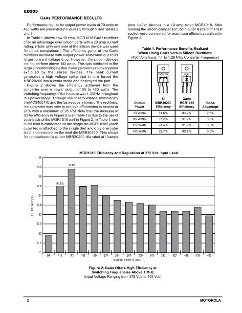
Figure 2 shows the efficiency achieved from the<br />
converter over a power output of 96 to 460 watts. The<br />
switch<strong>in</strong>g frequency of the <strong>in</strong>ductor was 1.2 MHz throughout<br />
this power range. Through use of zero voltage switch<strong>in</strong>g by<br />
the MC34067 IC and the fast recovery times of the rectifiers,<br />
the converter was able to achieve efficiencies <strong>in</strong> excess of<br />
91% with a maximum of 95.4%! Note that the <strong>in</strong>crease <strong>in</strong><br />
<strong>GaAs</strong> efficiency <strong>in</strong> Figure 2 over Table 1 is due to the use of<br />
both leads of the MGR1018 part <strong>in</strong> Figure 2. In Table 1, one<br />
outer lead is connected on the s<strong>in</strong>gle die MGR10180 (each<br />
outer leg is attached to the s<strong>in</strong>gle die) and only one outer<br />
lead is connected on the dual die MBR20200. This allows<br />
for comparison of a silicon MBR20200, die rated at 10 amps<br />
(one half of device) to a 10 amp rated MGR1018. After<br />
runn<strong>in</strong>g the silicon comparison, both outer leads of the test<br />
socket were connected for maximum efficiency realized <strong>in</strong><br />
Figure 2.<br />
Table 1. Performance Benefits Realized<br />
When Us<strong>in</strong>g <strong>GaAs</strong> versus Silicon <strong>Rectifiers</strong><br />
(400 Volts Input, 1.1 to 1.29 MHz Converter Frequency)<br />
Output<br />
Power<br />
Center Tap<br />
Si<br />
MBR20200<br />
<strong>Efficiency</strong><br />
S<strong>in</strong>gle<br />
<strong>GaAs</strong><br />
MGR1018<br />
<strong>Efficiency</strong><br />
<strong>GaAs</strong><br />
Advantage<br />
73 Watts 81.6% 84.2% 2.6%<br />
95 Watts 87.2% 91.2% 3.9%<br />
119 Watts 91.4% 91.9% 0.5%<br />
143 Watts 92.7% 92.7% 0.0%<br />
96<br />
MGR1018 <strong>Efficiency</strong> and Regulation at 375 Vdc Input Level<br />
95.5<br />
95.4%<br />
95<br />
94.5<br />
94.5%<br />
EFFICIENCY (%)<br />
94<br />
93.5<br />
93<br />
92.5<br />
92<br />
91.5<br />
91<br />
96 119 143 166 189 237 264 287 309 343 380 427 449 455 462<br />
OUTPUT POWER (WATTS)<br />
Figure 2. <strong>GaAs</strong> <strong>Offer</strong>s <strong>High</strong> <strong>Efficiency</strong> at<br />
Switch<strong>in</strong>g Frequencies Above 1 MHz<br />
(Input Voltage Rang<strong>in</strong>g from 375 Vdc to 405 Vdc)<br />
2 MOTOROLA