Installation & Service Manual - Hill Phoenix
Installation & Service Manual - Hill Phoenix
Installation & Service Manual - Hill Phoenix

You also want an ePaper? Increase the reach of your titles
YUMPU automatically turns print PDFs into web optimized ePapers that Google loves.
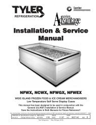
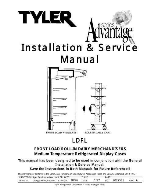
<strong>Installation</strong> & <strong>Service</strong><br />
<strong>Manual</strong><br />
LDFL<br />
FRONT LOAD ROLL-IN DAIRY MERCHANDISERS<br />
Medium Temperature Refrigerated Display Cases<br />
This manual has been designed to be used in conjunction with the General<br />
<strong>Installation</strong> & <strong>Service</strong> <strong>Manual</strong>.<br />
Save the Instructions in Both <strong>Manual</strong>s for Future Reference!!<br />
This merchandiser conforms to the Commercial Refrigeration Manufacturers Association Health and Sanitation standard CRS-S1-96.<br />
PRINTED IN Specifications subject to REPLACES ISSUE PART<br />
IN U.S.A. change without notice. EDITION 10/96 DATE 1/97 NO. 9027545 REV. A<br />
Tyler Refrigeration Corporation * Niles, Michigan 49120
<strong>Installation</strong> & <strong>Service</strong> <strong>Manual</strong><br />
LDFL<br />
CONTENTS<br />
Page<br />
Specifications<br />
LDFL Specification Sheets . . . . . . . . . . . . . . . . . . . . . . . . . . . . . . . 4<br />
Pre-<strong>Installation</strong> Responsibilities . . . . . . . . . . . (See General I&S <strong>Manual</strong>)<br />
<strong>Installation</strong> Procedures<br />
Carpentry Procedures . . . . . . . . . . . . . . . . . . . . . . . . . . . . . . . . . 6<br />
Leveling the Cases . . . . . . . . . . . . . . . . . . . . . . . . . . . . . . . . . . . . . 6<br />
Joining Cases . . . . . . . . . . . . . . . . . . . . . . . . . . . . . . . . . . . . . . . . 6<br />
Sealing Joints . . . . . . . . . . . . . . . . . . . . . . . . . . . . . . . . . . . . . . . . 6<br />
Special Instructions . . . . . . . . . . . . . . . . . . . . . . . . . . . . . . . . . . . . 6<br />
Refrigeration Procedures . . . . . . . . . . . (See General I&S <strong>Manual</strong>)<br />
Patch Ends . . . . . . . . . . . . . . . . . . . . . . . . . . . . . . . . . . . . . . . . . . 9<br />
Supporting Cases From the Building . . . . . . . . . . . . . . . . . . . . 10<br />
Joint Trim Filler Kit . . . . . . . . . . . . . . . . . . . . . . . . . . . . . . . . . . . . 13<br />
Patch End Joint Trim Assembly Filler Kit . . . . . . . . . . . . . . . . . . . . 14<br />
Hood Assembly . . . . . . . . . . . . . . . . . . . . . . . . . . . . . . . . . . . . . . 15<br />
Shelving and Shelf Base <strong>Installation</strong> . . . . . . . . . . . . . . . . . . . . . 16<br />
<strong>Installation</strong> Procedure Check Lists . . . . (See General I&S <strong>Manual</strong>)<br />
Wiring Diagrams . . . . . . . . . . . . . . . . . . . . . . . . . . . . . . . . . . . . . . . . . . 16<br />
LDFL Domestic & Export (50Hz) 8’ Case Circuits . . . . . . . . . . . . . 17<br />
LDFL Domestic & Export (50Hz) 12’ Case Circuits . . . . . . . . . . . . 18<br />
Cleaning and Sanitation . . . . . . . . . . . . . . . . . . (See General I&S <strong>Manual</strong>)<br />
Parts Information<br />
Operational Parts List . . . . . . . . . . . . . . . . . . . . . . . . . . . . . . . . . 19<br />
Cladding and Trim Parts List . . . . . . . . . . . . . . . . . . . . . . . . . . . 20<br />
TYLER Warranty . . . . . . . . . . . . . . . . . . . . . . . (See General I&S <strong>Manual</strong>)<br />
The following Medium Temperature Front Load Roll-In Dairy Merchandiser models<br />
are covered in this manual:<br />
MODELS<br />
LDFL<br />
DESCRIPTION<br />
8’ & 12’ FRONT LOAD ROLL-IN DAIRY MERCHANDISER<br />
January, 1997 Page 3
LDFL<br />
Tyler Refrigeration<br />
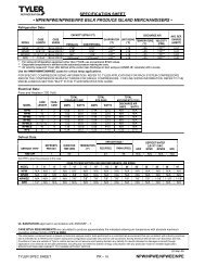
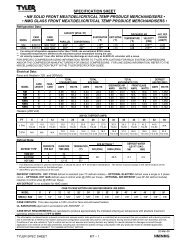
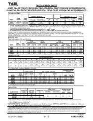
SPECIFICATIONS<br />
LDFL Front Load Roll-In Dairy Merchandiser Specification Sheets<br />
Page 4 October, 1996
<strong>Installation</strong> & <strong>Service</strong> <strong>Manual</strong><br />
LDFL<br />
LDFL Front Load Roll-In Dairy Merchandiser<br />
January, 1998 Page 5
LDFL<br />
INSTALLATION PROCEDURES<br />
Carpentry Procedures<br />
Leveling the Cases<br />
Check the levelness of the floor area to be<br />
used. The floor surface where this case is to<br />
be located should be as smooth and level as<br />
possible. Be sure there are no large bumps or<br />
dips in the floor. Insert shims under the case<br />
where necessary. The highest area of the lineup<br />
will have to be the determining high level<br />
point. The cases can then be leveled and<br />
joined from a level case at the high point.<br />
Level cases are necessary for both case pullups<br />
and proper operation. Small metal shims<br />
are furnished in the pull-up parts kit.<br />
Joining Cases<br />
Pull-up parts are shipped with the case in a<br />
“Blister-pack”. A list of parts furnished and<br />
where they are used is in the pack. Not all<br />
parts may be necessary for a particular case.<br />
Access panels must be removed to install pullup<br />
hardware.<br />
CAUTION<br />
Cases must be pushed together as close as<br />
possible before pulling them together with<br />
the pull-up bolt hardware.<br />
Pull-up angles in the cases are factory installed<br />
for ease of field installation. Adjacent foam<br />
cases in a line-up may require different<br />
amounts of shimming to bring the cases into<br />
proper alignment.<br />
Joint and end trims are shown elsewhere in<br />
this manual. Follow these instructions to complete<br />
assembly of these cases.<br />
Patch ends are shipped loose because of shipping<br />
height limitations. Patch end kit drawings<br />
are provided in this manual.<br />
Sealing Joints<br />
Tyler Refrigeration<br />
Tubes of caulking compound are furnished in<br />
the blister pack. The best time to make a<br />
waterproof case joint is at installation. It is<br />
recommended that two beads of caulking be<br />
used, one inside of the foam gasket for sanitation<br />
and one outside of the foam gasket for<br />
refrigeration. For an added measure of sealing,<br />
air-conditioning/heating duct tape can be<br />
used under inside joint trims.<br />
See “General I&S <strong>Manual</strong>” for proper<br />
refrigeration line installation and sealing.<br />
Special Instructions<br />
Be sure to read and understand the special<br />
instructions on handling these cases in this<br />
manual. Pay particular attention to the sections<br />
dealing with the anchoring of these<br />
cases to walls and/or roof structures.<br />
WARNING<br />
These cases are top heavy and require two<br />
or more people to move and/or position<br />
them. Improper handling of these cases<br />
could result in personal injury.<br />
1. Remove the items packed on the skid.<br />
2. Carefully raise the case (1) by tilting forward<br />
far enough to get enough clearance<br />
for the rear wall extension (2).<br />
Page 6 October, 1996
<strong>Installation</strong> & <strong>Service</strong> <strong>Manual</strong><br />
LDFL<br />
3. Apply the grey pressure sensative gasket<br />
(3) on both sides of the black foam gasket<br />
on the rear wall extension (2).<br />
4. Install the rear wall extension (2) to the<br />
bottom of the case (1) with four bolts (4),<br />
washers (5) and nuts (6).<br />
5. Install drain extension (7) on the bottom<br />
of the case (1) and secure with a hose<br />
clamp (8).<br />
6. Move the case against the wall where it is<br />
to be located. Raise the telescoping<br />
extensions (9) and secure the case to the<br />
wall (or specifically designed structure).<br />
7. Remove the rest of the skid.<br />
8. Pilot drill 3/16” holes in rear wall extension<br />
(2) and install the base cladding (10) with<br />
self tapping screws.<br />
9. Install joint trims and pull-ups per joint<br />
trim kit drawing.<br />
10. Install patch ends per the patch end kit<br />
drawing.<br />
October, 1996 Page 7
LDFL<br />
Tyler Refrigeration<br />
NOTE<br />
Since the top panel is the service<br />
access panel for fans and refrigeration<br />
lines, it must be kept clear.<br />
Waste Outlet - Floor Drain<br />
The preferred method is an in floor drain.<br />
Position drain so floor sweepings can not be<br />
swept into the drain.<br />
The alternate method is a flush drain, where<br />
permitted. NOTE: Do not slope floors,<br />
since trucks need a flat platform.<br />
IMPORTANT<br />
The information herein is only a general<br />
recommendation since store structures<br />
vary in strength and design. It is therefore<br />
necessary that the installing contractor<br />
and user assure themselves of the structural<br />
integrity of a chosen means of supporting<br />
these cases. TYLER can assume<br />
no liability for the consequences which<br />
may result from failure of structures or<br />
structural connections between this case<br />
and parts of a building.<br />
Page 8 October, 1996
<strong>Installation</strong> & <strong>Service</strong> <strong>Manual</strong><br />
LDFL<br />
Patch Ends<br />
A single case is self-supporting with the ends<br />
carrying the weight. Shipping height limitations<br />
make it necessary to ship the case without<br />
ends. They must be installed on location<br />
after the rear wall extension is added to the<br />
case.<br />
One inch structural partitions are available for<br />
use on line-ups.<br />
The one inch structural partition can be used<br />
between every case so that the entire line-up<br />
will be self-supporting. A drawback is that<br />
the partitions limit flexibility.<br />
The recommended method of supporting<br />
cases calls for supporting the cases from<br />
existing or specially constructed structures.<br />
Copy of label attached to each front load air<br />
skreen display case.<br />
IMPORTANT NOTICE<br />
This case was designed to provide a high<br />
degree of display flexibility in shelving and<br />
in roll-in carts. The base structure has<br />
been eliminated, making the merchandiser<br />
dependent upon support from walls and/or<br />
roof members. Single 8’ or 12’ cases can<br />
also be supported from patch ends.<br />
When two or more cases are to be<br />
installed and assembled, the cases must<br />
be attached to structural walls and/or<br />
structural portions of the roof . This meets<br />
the case weight requirement of 150 lb. per<br />
lineal foot .<br />
WARNING<br />
If this case is part of a line-up that requires<br />
disassembly, use great care during disassembly.<br />
The case line-up is not self-supporting<br />
and could injure or cause death if<br />
it fell.<br />
October, 1996 Page 9
LDFL<br />
Tyler Refrigeration<br />
Support Cases From The Building<br />
Installing cases in a continuous line-up to<br />
support the cases and to carry all possible<br />
additional shelving loads can be done in several<br />
ways:<br />
1. A case line-up can be set close to a wall<br />
and gain support from it.<br />
2. When no building wall is available,<br />
the case may be cable attached to<br />
the roof structure. Truss work might<br />
also be used. There are pre-drilled<br />
holes on the ends of each case so<br />
that 3/8” eyebolts or other bolts (up<br />
to 1/2”) can be used. 1/4” cable<br />
with a minumum 2000 lb. tensile<br />
strength is recommended. The<br />
base must be anchored to the floor<br />
and sway bars as necessary must<br />
be used.<br />
3. Columns may be run from floor to<br />
ceiling with a girder for case attachment.<br />
4. Overhead structures can be used to<br />
support the cases and/or store<br />
decor from above.<br />
IMPORTANT<br />
The information herein is only a general recommendation<br />
since store structures vary in strength and design.<br />
It is therefore necessary that the installing contractor<br />
and user assure themselves of the structural integrity<br />
of a chosen means of supporting these cases. TYLER<br />
can assume no liability for the consequences which<br />
may result from failure of structures or structural connections<br />
between this case and parts of a building.<br />
Page 10 October, 1996
<strong>Installation</strong> & <strong>Service</strong> <strong>Manual</strong><br />
LDFL<br />
Rear column mounted in concrete<br />
Line-up may be supported by various<br />
beam details<br />
Case has<br />
back and top<br />
LDFL suspension system rear<br />
mounted column<br />
January, 1997 Page 11
LDFL<br />
Tyler Refrigeration<br />
Page 12 October, 1996
<strong>Installation</strong> & <strong>Service</strong> <strong>Manual</strong><br />
LDFL<br />
October, 1996 Page 13
LDFL<br />
Tyler Refrigeration<br />
Page 14 October, 1996
<strong>Installation</strong> & <strong>Service</strong> <strong>Manual</strong><br />
LDFL<br />
Hood Assembly<br />
WARNING<br />
Make sure all power is off to the case.<br />
Electrical servicing should always be done<br />
by a qualified electrician. Improper servicing<br />
could result in product damage and/or<br />
personal injury.<br />
1. Pull the 3-prong female receptacle (1)<br />
through the hood extension weld assembly<br />
(2).<br />
2. Fasten hood extension weld assembly (2)<br />
to the canopy (3) with tappit screws (4).<br />
3. Hook the light channel assembly (5) into<br />
the front lip of the front hood (6).<br />
4. Plug the light channel wire (7) into the<br />
female receptacle (1).<br />
5. Swing the light channel assembly (5) up<br />
into place and secure with truss head<br />
screws (8).<br />
6. Install top front cladding (9) over ballast<br />
(10) with screws (11).<br />
7. Complete the assembly by installing the<br />
hood extension joint trim (12) with truss<br />
head screws (13).<br />
December, 1997 Page 15
LDFL<br />
Tyler Refrigeration<br />
Shelving and Shelf Base <strong>Installation</strong><br />
When 48” shelving is to be used, installation<br />
is as in conventional cases. 24” and 48” shelf<br />
bases can be used, or shelves can be mounted<br />
above roll-in carts. If 24” shelves are<br />
used, it is necessary to attach uprights at a<br />
24” spacing as shown to the right. The<br />
uprights are symetrical so they can be used<br />
for right or left hand applications just by<br />
reversing them. Pilot drill 3/16” on a line 3<br />
1/4” down from the top. This also coincides<br />
with the centerline of the top slot on the builtin<br />
shelving uprights. Attach the uprights with<br />
the provided hex head screws at top and bottom<br />
using the upper hole in each pair of<br />
holes in the upright.<br />
Shelf Bases<br />
Shelf bases are 24” or 48” wide.<br />
Fronts for the shelf bases are 24,<br />
48, 96 or 144” wide. Front ducts<br />
attach to the bases with “Hedlok”<br />
fasteners. These plastic interlocking<br />
devices provide easy removal,<br />
yet hold the front ducts securely.<br />
Just pry up to remove. Push in<br />
place to install.<br />
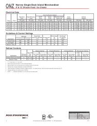
WIRING DIAGRAM<br />
ELECTRICIAN NOTE - OVERCURRENT<br />
PROTECTION<br />
120V circuits should be protected by 15 or 20 Amp devices per the requirements noted on the cabinet nameplate<br />
or the National Electrical Code, Canadian Electrical Code - Part 1, Section 28. 208V defrost circuits<br />
employ No. 12 AWG field wire leads for field connections. On remote cases intended for end to end line-ups,<br />
bonding for ground may rely upon the pull-up bolts.<br />
Page 16 October, 1996
January, 1997 Page 17
Page 18 January, 1997
<strong>Installation</strong> & <strong>Service</strong> <strong>Manual</strong><br />
LDFL<br />
PARTS INFORMATION<br />
Operational Parts List<br />
Case Usage Domestic Export<br />
Electrical Circuit 115 Volt 60 Hertz 220 Volt 50 Hertz<br />
Case Size 8’ 12’ 8’ 12’<br />
Fan Motor 5243498 5243498 5223696 5223696<br />
9 Watt 9 Watt 18.3 Watt 18.3 Watt<br />
Fan Motor Brackets 5205112 5205112 5205112 5205112<br />
Fan Blades (8.75” 31° 3B) 5104858 5104858 ---- ----<br />
(8.75” 26° 3B) ---- ---- 5054140 5154140<br />
T-8 Lamp Ballast (canopy)<br />
(1st & 2nd row) 5966635 5991030 9028439 9028438<br />
(3rd row) 5991029 5991030 9028437 9028438<br />
Opt. 800MA Lamp Ballast<br />
(canopy)(1st & 2nd row) 5204769 5049140 5204859 5204859<br />
(3rd row) 5049140 5049140 5989796 5989796<br />
T-8 Lampholder (canopy) 5232279 5232279 5232279 5232279<br />
800MA Lampholder (canopy)<br />
(telescoping) 5614628 5614628 5614628 5614628<br />
(stationary) 5614629 5614629 5614629 5614629<br />
Light Switch (SPST) 5100565 5100565 5100565 5100565<br />
Anti-Sweat Heater<br />
(air grid retainer) 5124818 5124819 5081149 5081150<br />
For information on operational parts not listed above contact the TYLER <strong>Service</strong> Parts<br />
Department.<br />
January, 1997 Page 19
LDFL<br />
Tyler Refrigeration<br />
Cladding and Trim Parts List<br />
Item Description<br />
LDFL<br />
8’ 12’<br />
1 Screw (per close-off panel assy) 1309067 (9) 1309067 (12)<br />
2 Close-off Panel Assembly 9026544 9026546<br />
3 Screw (per top cover) 5183536 (5) 5183536 (5)<br />
4 Top Cover 5186277 5186278<br />
5 Lower Close-off Panel 9026548 9026548<br />
Screw (per lower close-off) 5183536 (2) 5183536 (2)<br />
6 Close-off Panel Assembly 9026544 9026546<br />
Screw (per close-off panel assy) 1309067 (9) 1309067 (12)<br />
7 Screw (per canopy) 5183536 (4) 5183536 (6)<br />
8 Front Canopy Hood, Painted 9025223 9025224<br />
9 Canopy Hood Backer, Painted 9025983 9025983<br />
10 Screw (per backer) 5205439 (2) 5205439 (2)<br />
11 Standard Hood Joint Trim 5222015 5222015<br />
Short Hood Joint Trim 5222048 5222048<br />
12 Screw (per hood joint trim) 5205439 (6) 5205439 (6)<br />
13 Light Channel Joint Trim 5222014 5222014<br />
14 Bumper Retainer 9025504 9025506<br />
15 Color Band, Painted NA NA<br />
16 Color Band Backer, Painted NA NA<br />
17 Bumper End Trim ---- color by order ----<br />
18 Bumper Backer ---- color by order ----<br />
19 Bumper ---- color by order ----<br />
20 Front Lower Cladding, Painted NA NA<br />
21 Rivet (per lower cladding) 5104702 (6) 5104702 (6)<br />
22 Shoulder Screw (per lower cladding) 9025833 (16) 9025833 (24)<br />
23 Base Extension Assembly 5055027 5055028<br />
Foam Base Extension 5054973 5054974<br />
Reinforcement Channel 5055031 5055032<br />
24 Screw (per channel) 1309067 (6) 1309067 (8)<br />
25 Screw (per cart stop joint trim) 5205439 (2) 5205439 (2)<br />
26 Cart Stop Joint Trim 5184553 5184553<br />
27 Cart Stop Assembly 5184559 5184560<br />
28 Screw (per cart stop assembly) 5183536 (6) 5183536 (10)<br />
29 Raceway Cover 5184498 5184499<br />
Screw (per raceway cover) 5111197 (7) 5111197 (9)<br />
30 Raceway Assembly 5184500 5184501<br />
Page 20 January, 1997
<strong>Installation</strong> & <strong>Service</strong> <strong>Manual</strong><br />
LDFL<br />
Item Description 8’ 12’<br />
31 Screw (per raceway assembly) 5183536 (6) 5183536 (8)<br />
32 Screw (raceway cover plate) 5111197 (7) 5111197 (9)<br />
33 Raceway Cover Plate 5184497 (2) 5184497 (2)<br />
34 Nut (per end spacers) 5100634 (2) 5100634 (2)<br />
35 Lock Washer (per end spacers) 5101006 (2) 5101006 (2)<br />
36 Flat Washer (per end spacers) 5100979 (4) 5100979 (4)<br />
37 Machine Screw (per end spacers) 5107443 (2) 5107443 (2)<br />
38 Nut (per end spacers) 5100643 (6) 5100643 (6)<br />
39 Lock Washer (per end spacers) 5628631 (6) 5628631 (6)<br />
40 Flat Washer (per end spacers) 5100982 (12) 5100982 (12)<br />
41 Machine Screw (per end spacers) 5120913 (6) 5120913 (6)<br />
42 Rivet (per end spacers) 5105037 (8) 5105037 (8)<br />
43 End Spacer 5184602 (2) 5184602 (2)<br />
January, 1997 Page 21