TECHNICAL INFORMATION - Association of Engineers Kerala
TECHNICAL INFORMATION - Association of Engineers Kerala
TECHNICAL INFORMATION - Association of Engineers Kerala

You also want an ePaper? Increase the reach of your titles
YUMPU automatically turns print PDFs into web optimized ePapers that Google loves.
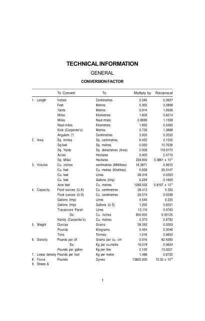
<strong>TECHNICAL</strong> <strong>INFORMATION</strong><br />
GENERAL<br />
CONVERSION FACTOR<br />
To Convert To Multiply by Reciprocal<br />
1. Length Inches Centimetres 2.540 0.3937<br />
Feet Metres 0.305 3.2808<br />
Yards Metres 0.914 1.0936<br />
Miles Kilometres 1.609 0.6214<br />
Miles Naut-miles 0.8690 1.1508<br />
Naut-miles Kilometres 1.852 0.5400<br />
Kole (Carpenter's) Metres 0.720 1.3888<br />
Angulam (") Centimetres 3,000 0.3333<br />
2. Area Sq. inches Sq. centimetres 6.452 0.1550<br />
Sq.feet Sq. metres 0.093 10.7636<br />
Sq. Yards Sq. dekametres (Ares) 0.008 119.6170<br />
Acres Hectares 0.405 2.4710<br />
Sq. Miles Hectares 259.000 0.3861 x 10 -2<br />
3. Volume Cu. inches centimetres (Millilitres) 16.3871 0.0610<br />
Cu. feet Cu. metres (Kilolitres) 0.028 35.3147<br />
Cu. feet Litres 28.316 0.0353<br />
Cu. feet Gallons (Imp) 6.229 0.1605<br />
Acre feet Cu. metres 1283.502 0.8107 x 10 -3<br />
4. Capacity Fluid ounces (U.K) Cu. centimetres 28.413 0.352<br />
Fluid ounces (U.S) Cu. centimetres 29.574 0.0338<br />
Gallons (Imp) Litres 4.546 0.220<br />
Gallons (Imp) Gallons (U.S) 1.200 0.8331<br />
Travancore Parah Litres 13.110 0.0763<br />
Do. Cu. inches 800.000 0.00125<br />
Kandy (Carpenter's) Cu. metres 0.373 2.6792<br />
5. Weight Ounces Grams 28.350 0.0353<br />
Pounds Kilograms 0.454 2.2046<br />
Tons Tonnes 1.016 0.9842<br />
6. Density Pounds per cft Grams per cu. cm 0.016 62.4283<br />
Do. Kg per cu.metre 16.019 0.0624<br />
Pounds per gallon Kg per litre 0.100 10.0221<br />
7. Linear density Pounds per foot Kg per metre 1.488 0.6720<br />
8. Force Pounds Dynes 13825.500 72.33 x 10 -6<br />
9. Strees &<br />
1
To Convert To Multiply by Reciprocal<br />
Pressure Newton per sq.mm Kg.per Sq. cm 10.97 0.0981<br />
Pounds per sq. inch Do. 0.703 14.2248<br />
Pounds per sq.foot Kg. per Sq.m. 4.882 0.2048<br />
Tons per sq. foot Tonnes per Sq.m. 10.937 0.0914<br />
Head <strong>of</strong> water in feet Pounds per Sq. in. 0.434 2.3067<br />
Do. Kg per Sq. cm. 0.035 32.8093<br />
Inches <strong>of</strong> mercury Do. 0.035 28.9590<br />
Do. Pounds per Sq.in. 0.491 2.0360<br />
10. Power Horse power Metric horse power 1.014 0.9863<br />
Do. Kilowatts 0.746 1.3410<br />
Foot pounds per second Do. 0.1356 x 10 2 737.562<br />
11. Velocity Feet second Miles per hour 0.682 1.4667<br />
Do. Kilometres per hour 1.097 0.9113<br />
Milles per hour Centimetres per sec. 44.704 0.0224<br />
12. Temperature (Fahrenheit) (Centigrade) (F-32) x 5/9 (c x 9/5) + 32<br />
13. Moment <strong>of</strong><br />
inertia Inch units Centimetre units 41.623 0.0240<br />
Foot units Metre units 0.009 115.8620<br />
14. Section<br />
Modulus Inch units Centimetre units 16.387 0.0610<br />
Foot units Metre units 0.283 35.3147<br />
15. Bending<br />
moment Foot pounds Kilogram metres 0.138 7.2330<br />
Inch pounds Kilogram centimetres 1.152 0.8680<br />
16. Momentum Pound foot per sec. Kg. metre per sec. 0.138 7.2330<br />
17. Illumination Foot candle Lux 10.764 0.0929<br />
TABLE OF CIRCUMFERENCE AND AREAS OF PLANE FIGURES<br />
Title Area Cicumference<br />
or Perimeter<br />
Rectangle lb 2(l+b)<br />
Square a 2 4a<br />
Triangle S(s - a)(s - b)(s - c) a + b + c = 2s<br />
Equilateral triangle =<br />
2<br />
3a<br />
4<br />
= 0.433a 2 3a<br />
Isosceless right angled triangle 0.5a 2 3.414a<br />
Hexagon (regular) 3a2 2<br />
3a<br />
3<br />
2<br />
= 2.6a2 6a<br />
Circle �r2 2<br />
or �d 2� r or �d<br />
Sector <strong>of</strong> circle<br />
2 0<br />
�d<br />
x n<br />
360<br />
2<br />
4<br />
2<br />
v<br />
0.5<br />
2g
Segment <strong>of</strong> Circle Area <strong>of</strong> Sector, Area <strong>of</strong><br />
Triangle or approx:<br />
2/3 maximum ht. x width<br />
Ellipse �ab �(a+b) appx<br />
Note: Area <strong>of</strong> similar figures will be proportional to the square <strong>of</strong> their corresponding sides.<br />
1.3. VOLUME AND SURFACE AREAS OF SOLIDS<br />
Title Volume Surface Area<br />
Prism Base area x height Circumference <strong>of</strong><br />
base x height<br />
Cylinders �r2h 2�rh<br />
Sphere 4/3�r3 3<br />
�d<br />
=<br />
4�r<br />
6<br />
2<br />
Pyramid 1/3 base area x height 1/2 perimeter x slant<br />
h<br />
Frustum <strong>of</strong> pyramid �(A B<br />
+ A<br />
b<br />
+ A<br />
B<br />
.A<br />
b �<br />
3<br />
3<br />
height<br />
WEIGHT, AREA & PERIMETER OF STEEL BARS<br />
Dia ROUNDS SQUARE BARS<br />
Width Wt Area Peri Wt. Area Peri.<br />
m m kg. cm 2 c m kg. cm 2 c m<br />
5.0 0.15 0.20 1.57 0.20 0.25 2.0<br />
5.5 0.19 0.24 1.73 0.24 0.30 2.2<br />
6.0 0.22 0.28 1.88 0.28 0.36 2.4<br />
7.0 0.30 0.38 2.20 0.38 0.49 2.8<br />
8.0 0.39 0.50 2.51 0.50 0.64 3.2<br />
9.0 0.50 0.64 2.83 0.64 0.81 3.6<br />
10 0.62 0.79 3.14 0.78 1.00 4.0<br />
11 0.75 0.95 3.46 0.95 1.21 4.4<br />
12 0.89 1.13 3.77 1.13 1.44 4.8<br />
14 1.21 1.54 4.40 1.54 1.96 5.6<br />
16 1.58 2.01 5.03 2.01 2.56 6.4<br />
18 2.00 2.54 5.65 2.54 3.24 7.2<br />
20 2.47 3.14 6.28 3.14 4.00 8.0<br />
22 2.98 3.80 6.91 3.80 4.84 8.8<br />
25 3.85 4.91 7.85 4.91 6.25 10.0<br />
28 4.83 6.16 8.80 6.15 7.84 11.2<br />
32 6.31 8.04 10.05 8.04 10.24 12.8<br />
36 7.99 10.18 11.31 10.17 12.96 14.4<br />
40 9.86 12.57 12.57 12.56 16.0 16.0<br />
45 12.49 15.90 14.14 15.90 20.25 18.0<br />
50 15.41 19.64 15.71 19.62 25.00 20.0<br />
56 19.34 24.63 17.59 24.62 31.36 22.4<br />
63 24.47 31.17 19.79 31.16 39.69 25.2<br />
71 31.08 39.59 22.31 39.57 50.41 28.4<br />
80 39.46 50.27 25.13 50.24 64.00 32.0<br />
90 49.94 63.62 28.27 63.58 81.00 36.0<br />
100 61.66 78.54 31.42 78.50 100.00 40.0<br />
110 74.60 95.03 34.56 94.98 121.00 44.0<br />
125 96.34 122.72 39.27 122.66 156.25 450.0<br />
140 120.84 153.94 43.98 153.86 196.00 56.0<br />
160 157.84 201.06 50.27 200.96 256.00 64.0<br />
180 199.76 254.47 56.55 254.34 324.00 72.0<br />
200 246.62 316.16 62.83 314.00 400.00 80.0
REGULAR POLYGON<br />
A = na 2 /4 cot ( � /n) = nr 2 tan ( � /n)<br />
= nR 2 /2 sin (2 � /n)<br />
n = no: <strong>of</strong> sides, a = side r= Radius <strong>of</strong> inscribed circle<br />
R= Radius <strong>of</strong> circumscribed circle.<br />
Name <strong>of</strong> No. Angle Value <strong>of</strong> factor x<br />
Polygon <strong>of</strong> in<br />
sides Degrees A=a 2 x r=ax R= ax Side a =R x Side a =r x<br />
Triangle 3 60 0.433 0.289 0.577 1.732 3.464<br />
Tetragon 4 90 1.000 0.500 0.707 1.414 2.000<br />
Pentagon 5 108 1.721 0.688 0.861 1.176 1.454<br />
Hexagon 6 120 2.598 0.866 1.000 1.000 1.155<br />
Octagon 8 135 4.828 1.207 1.307 0.765 0.828<br />
Decagon 10 144 7.694 1.538 1.618 0.618 0.650<br />
Dodecagon 12 150 11.196 1.866 1.932 0.517 0.543<br />
AREA OF IRREGULAR PLANE FIGURES<br />
Trapezoidal Rule<br />
� y0 � yn<br />
�<br />
A � h � � y1 � y2 � ... � yn�1<br />
2<br />
�<br />
� �<br />
Simpson's rule<br />
� � 4 � ... � 2 � ... �<br />
A � h � y � y � y � y � � y � y � y � � y �<br />
� 0 n 1 3 n�1 2 4 n�2<br />
�<br />
[Devide the area or figure into an even number 'n' <strong>of</strong> parallel strips by means <strong>of</strong> (n+1) ordinates paced<br />
equal distance]<br />
- - - - - - - - - - - - - - - - - - - - - - - - - - - - - - - - - - - - - - - - - - - - - - - - - - - - - - - - - - - - - - - - - - - - - - - - - - - - - - - - - - - - - - - - - - - - - - - - - - - - - - - -<br />
- - - - - - - - - - - - - - - - - - - - - - - - - - - - - - - - - - - - - - - - - - - - - - - - - - - - - - - - - - - - - - - - - - - - - - - - - - - - - - - - - - - - - - - - - - - - - - - - - - - - - - - -<br />
.- - - - - - - - - - - - - - - - - - - - - - - - - - - - - - - - - - - - - - - - - - - - - - - - - - - - - - - - - - - - - - - - - - - - - - - - - - - - - - - - - - - - - - - - - - - - - - - - - - - - - - -<br />
.- - - - - - - - - - - - - - - - - - - - - - - - - - - - - - - - - - - - - - - - - - - - - - - - - - - - - - - - - - - - - - - - - - - - - - - - - - - - - - - - - - - - - - - - - - - - - - - - - - - - - - -<br />
- - - - - - - - - - - - - - - - - - - - - - - - - - - - - - - - - - - - - - - - - - - - - - - - - - - - - - - - - - - - - - - - - - - - - - - - - - - - - - - - - - - - - - - - - - - - - - - - - - - - - - - -<br />
- - - - - - - - - - - - - - - - - - - - - - - - - - - - - - - - - - - - - - - - - - - - - - - - - - - - - - - - - - - - - - - - - - - - - - - - - - - - - - - - - - - - - - - - - - - - - - - - - - - - - - - -<br />
4
DEFINITION OF FUNCTION<br />
b<br />
Sin�<br />
�<br />
c<br />
a<br />
Cos�<br />
�<br />
c<br />
b Sin�<br />
Tan�<br />
� �<br />
a Cos�<br />
c 1<br />
Cosec � � �<br />
b Sin�<br />
c 1<br />
Sec�<br />
� �<br />
a Cos�<br />
a Cos� 1<br />
Cot�<br />
� � �<br />
b Sin� Tan�<br />
IMPORTANT IDENTITIES<br />
2 2<br />
Sin �� Cos � �1<br />
2 2<br />
1�Tan � � Sec �<br />
1 Cot Cosec<br />
2 2<br />
� � � �<br />
Values <strong>of</strong> trigonometric function<br />
Angle 0<br />
TRIGONOMETRY<br />
�<br />
6<br />
Sin 0 1 2<br />
Cos 1 3 2<br />
b<br />
5<br />
�<br />
4<br />
1 2<br />
1 2<br />
Tan 0 1 3 �<br />
Cosec � 2 2<br />
Sec 1<br />
1 3<br />
a<br />
c<br />
�<br />
3<br />
3 2<br />
1 2<br />
�<br />
2<br />
1<br />
0<br />
2 3 1<br />
2 3 2 2 �<br />
1 3<br />
Cot � 3 1 0
FUNCTIONS OF SUM AND DIFFERENCE OF TWO ANGLES<br />
� �<br />
� �<br />
Sin A � B � SinACosB � CosASinB<br />
Cos A � B � CosACosB � SinASinB<br />
TanA � TanB<br />
Tan �A � B�<br />
�<br />
1� TanATanB<br />
CotA � CotB<br />
Cot� A � B�<br />
�<br />
CotA � CotB<br />
FUNCTIONS OF SUM OF THREE ANGLES<br />
� �<br />
� �<br />
Sin A � B � C � SinACosBCosC � CosASinBCosC � CosACosBSinC �SinASinBSinC<br />
Cos A � B � C � CosACosBCosC � SinASinBCosC � SinACosBSinC � CosASinBSinC<br />
FUNCTIONS OF MULTIPLE ANGLES<br />
Sin2� � 2Sin�Cos� Sin3 3Sin 4Sin<br />
2<br />
� � � � �<br />
2<br />
Sin4 8Cos Sin 4Cos Sin<br />
Cos2 Cos Sin<br />
2 2<br />
� � � � �<br />
2<br />
Cos3 4Cos 3Cos<br />
4 2<br />
Cos4� � 8Cos � � 8Cos � �1<br />
Tan2<br />
Tan3<br />
� � � � � � �<br />
� � � � �<br />
2Tan�<br />
� � 2<br />
1� Tan �<br />
3<br />
3Tan� �Tan �<br />
� �<br />
2<br />
1� 3Tan �<br />
FUNDAMENTAL RELATIONS<br />
Sine Law<br />
a b c<br />
� � � 2R<br />
SinA SinB SinC<br />
Cosine Law 2 2 2<br />
a � b � c � 2bcCosA<br />
Tangent Law<br />
A � B<br />
Tan<br />
a � b<br />
� 2<br />
a � b A � B<br />
Tan<br />
2<br />
Projection Law a � bCosc � cCosB<br />
6<br />
Tan4<br />
Cot2�<br />
�<br />
Cot3�<br />
�<br />
Cot4�<br />
�<br />
3<br />
4Tan� � 4Tan �<br />
� � 2 4<br />
1� 6Tan � � 4Tan �<br />
2<br />
Cot � �1<br />
2Cot�<br />
� � �<br />
3Cot � �1<br />
3<br />
Cot 3Cot<br />
4 2<br />
Cot � � 6Cot � �1<br />
3<br />
4Cot � � 4Cot�<br />
LAWS OF LOGARITHMS<br />
� �<br />
log1 � 0,loga �1,log mn � log m � log n<br />
m<br />
n<br />
log x<br />
�<br />
m<br />
n<br />
log � log m � log n,log m � n log m<br />
m<br />
log x<br />
INDICES<br />
For Rational Values <strong>of</strong> m and n (if a, b are<br />
positive)<br />
� � m<br />
a � a � a , ab � a b<br />
m n m� n m m<br />
a<br />
a 1, a<br />
a<br />
0<br />
�<br />
m<br />
n �<br />
m� n
STRUCTURAL ENGINEERING<br />
Unit weight <strong>of</strong> Building materials [REF:IS 875 (Part 1) 1987]<br />
Sl. No Material Kg/m 3<br />
1 Aluminium (cast) 2580 - 2710<br />
2 Bitumen 1040<br />
3 Brick masonry (common burnt clay brick) 1920<br />
4 Brick masonry (engineering bricks) 2400<br />
5 Bricks 1600 - 1920<br />
6 Broken bricks 1010 - 1450<br />
7 Broken stone ballast- dry 1600 – 1870<br />
Broken stone ballast- wet 1920 - 2240<br />
8 Cement 1440<br />
9 Cement mortar 2080<br />
10 Clay 1440 - 2080<br />
11 Copper (cast) 8790 - 8940<br />
12 Dry rubble masonry 2080<br />
13 Earth (dry) 1410 – 1840<br />
Earth (wet) 1600 - 2000<br />
14 Glass (solid) 2400 - 2720<br />
15 Gold (cast) 19550 - 19330<br />
16 Granite 2640 - 2800<br />
17 Gravel (loose) 1600<br />
Gravel (rammed) 1920 - 2160<br />
18 Gypsum powder 1410 - 1760<br />
19 Laterite 2080 -2400<br />
20 Lime concrete 1920<br />
21 Lime mortar 1600 - 1840<br />
22 Lime slaked 580 - 640<br />
23 Lime stone 2400 - 2640<br />
24 Lime unslaked 880 - 1040<br />
25 Marble 2720<br />
26 News paper in bundles 400<br />
27 Paper (in bundles and rolls) 700<br />
28 Plain cement concrete 880 - 1920<br />
29 Plastics 1200 - 1380<br />
30 Prestressed cement concrete 2400<br />
31 Reinforced cement concrete 2310 - 2700<br />
32 River sand 1840<br />
33 Rubber 910 - 960<br />
34 Sand (dry) 1540 – 1600<br />
Sand (wet) 1760 - 2000<br />
35 Silver (cast) 10400 - 10490<br />
7
36 Steel sheets, railway rails etc 4490<br />
37 Stone masonry 2080 - 2700<br />
38 Surkhi (Brick dust) 1010<br />
39 Tar 1010<br />
40 Thread in bundles 500<br />
41 Timber Teak 640<br />
42 Water (fresh) 1000<br />
Water (salty) 1025<br />
Kg/m 2<br />
43 Aluminium sheet/mm thickness 2.8<br />
44 Asbestos cement sheeting (per m 2 )<br />
Corrugated (6mm thick)<br />
Semi-corrugated (6mm thick) 12 - 13<br />
Plain (5mm thick) 9.16<br />
45 Copper sheet/mm thickness 8.7<br />
46 Steel plate/mm thickness 8<br />
47 M.P tiles (per tile) 2 - 3 kg/Tile<br />
GALVANIZED IRON SHEETS<br />
(PLAIN AND CORRUGATED)<br />
(REF. IS 277:1985)<br />
B.G 16 18 20 22 24<br />
Thickness in mm 1.6 1.25 1.00 0.8 0.63<br />
Mass per m 2 Class I 13.31 10.50 8.60 7.03 5.7<br />
Class II 13.16 10.41 8.45 6.88 5.55<br />
Class III 13.01 10.26 8.30 6.73 5.40<br />
Class IV 12.94 10.19 8.22 6.66 5.32<br />
Classification is based on thickness <strong>of</strong> Zinc coating. Class I refers to sheets 750 g <strong>of</strong> zinc coating/<br />
m 2 .class II-600g. Class III-450g.Class IV 375g. Weight <strong>of</strong> corrugated sheets to be arrived at taking<br />
the weight <strong>of</strong> plane sheets used for the same. 660mm wide corrugated sheets are obtained from<br />
750mm, plain sheets and 800 mm corrugated sheets from 900mm plain sheets. Sheets are supplied<br />
in 1.8, 2.2,2.5,2.8, 3.2 m length.<br />
LIVE LOADS ON FLOORS (Ref. IS 875(Part 1) 1987)<br />
1. Houses, hospitals, hostels 200 kg/m 2<br />
2. Office floors 250-400 kg/m 2<br />
3. Banks, Reading rooms 300 kg/m 2<br />
4. Shop floors, work rooms, restaurants, auditoriums 400 kg/m 2<br />
5. Warehouses, workshops, factories for<br />
light wright loads, dance halls, waiting halls 500 kg/m 2<br />
6. Warehouses, workshops and factories for<br />
medium weight loads 750 kg/m 2<br />
7. Warehouses, workshops and factories for<br />
heavy weight loads, book stalls, libraries 1000 kg/m 2<br />
8<br />
�
�<br />
8. Stairs - balconies not liable to over-crowding 300 kg/m 2<br />
9. Stairs - balconies liable to over- crowding 500 kg/m 2<br />
Live loads on Ro<strong>of</strong>s<br />
1. Flat, sloping or curved upto 10 0<br />
(a) Access provided 150 kg/m 2<br />
(b) Access not provided 75 kg/m 2<br />
2. Sloping ro<strong>of</strong>-slope greater than 10 0 75 kg/m 2<br />
STRIPPING TIME FOR FORM WORK ( REF: IS 456-2000)<br />
No. Type <strong>of</strong> form work Minimum period<br />
before striking formwork<br />
1 Vertical formwork to columns, walls, beams 16-24 hours<br />
2 S<strong>of</strong>fit formwork to slabs (Props to be refixed<br />
immediately after removal <strong>of</strong> formwork) 3 days<br />
3 S<strong>of</strong>fit formwork to beams (Props to be refixed immediately<br />
after removal <strong>of</strong> formwork) 7 days<br />
4 Props to slabs<br />
1. Spanning upto 4.5 m 7 days<br />
2. Spanning over 4.5 m 14 days<br />
5 Props to beams and arches]<br />
1. Spanning upto 6 m 14 days<br />
2. Spanning over 6 m 21 days<br />
* In normal circumstances where ambient temperature does not fall below 15 0 C and where Ordinary<br />
Portland Cement is used and adequate curing is done.<br />
LIMIT STATE DESIGN OF SLAB<br />
(Ref. IS 456 2000)<br />
Slab is designed as a two way slab for critical case.<br />
Live load 3kN/m 2 , Concrete – M20. Fe 415 steel.<br />
thicknessT steel along shorter steel along longer span<br />
lx <strong>of</strong> slab span<br />
m cm � spacing � spacing<br />
3 10 8 170 8 240<br />
3 12 8 210 8 240<br />
3 14 8 220 8 240<br />
3 15 8 230 8 240<br />
3 17.5 8 230 8 240<br />
3.5 10 8 120 8 240<br />
3.5 12 8 140 8 240<br />
3.5 14 8 160 8 240<br />
3.5 15 8 170 8 240<br />
3.5 17.5 8 190 8 240<br />
3.5 20 8 200 8 240<br />
4 10 10 130 8 180<br />
4 12 10 160 8 210<br />
9
4 14 10 190 8 240<br />
4 15 10 200 8 240<br />
4 17.5 10 220 8 240<br />
4 20 10 240 8 240<br />
4 22.5 10 240 8 240<br />
4 25 10 260 8 240<br />
4.5 12 10 120 8 160<br />
4.5 14 10 140 8 190<br />
4.5 15 10 150 8 200<br />
4.5 17.5 10 170 8 240<br />
4.5 20 10 180 8 240<br />
4.5 22.5 10 190 8 240<br />
4.5 25 10 200 8 240<br />
5 12 12 130 10 200<br />
5 14 12 160 10 230<br />
5 15 12 170 10 240<br />
5 17.5 12 190 10 240<br />
5 20 12 210 10 240<br />
5 22.5 12 220 10 240<br />
5 25 12 230 10 240<br />
LIMIT STATE DESIGN OF SIMPLY SUPPORTED RECTANGULAR BEAM<br />
(Ref. IS 456 2000)<br />
Slab load 25kN/m, Concrete – M20 ; Fe 415 steel<br />
Effective span width depth steel at bottom steel at top<br />
3 230 400 4,12 2,12<br />
3 230 450 4,12 2,12<br />
3 250 400 2,16 2,12<br />
3 250 450 4,12 2,12<br />
3 300 400 2,16 2,12<br />
3 300 450 4,12 2,12<br />
4 230 400 2,12+2,16 2,12<br />
4 230 450 3,16 2,12<br />
4 250 400 2,12+2,16 2,12<br />
4 250 450 3,16 2,12<br />
4 300 400 2,12+2,16 2,12<br />
4 300 450 3,16 2,12<br />
5 230 400 4,20 2,12<br />
5 230 450 5,16 2,12<br />
5 250 400 4,20 2,12<br />
5 250 450 5,16 2,12<br />
5 300 400 4,20 2,12<br />
5 300 450 4,18 2,12<br />
6 230 400 5,20 2,20+1,12<br />
10
6 230 450 4,20+1,12 3,14<br />
6 250 400 6,18 2,20<br />
6 250 450 4,20+1,16 3,12<br />
6 300 400 4,20+2,16 2,18<br />
6 300 450 3,25 2,12<br />
LIMIT STATE DESIGN OF SQUARE COLUMN<br />
(Ref. IS 456 2000)<br />
Concrete – M25 ; Fe 415 steel<br />
size main bar links load carried by the<br />
column (N)<br />
no. Dia Dia spacing<br />
230x230 4 16 8 250 751703.9<br />
230x230 4 20 8 250 876974.8<br />
250x250 4 16 8 250 847703.9<br />
250x250 4 20 8 250 972974.8<br />
300x300 4 16 8 250 1122704<br />
300x300 4 20 8 250 1247975<br />
300x300 4 25 8 250 1443711<br />
400x 400 4 16 8 250 1822704<br />
400x 400 4 20 8 250 1947975<br />
400x 400 4 25 8 250 2143711<br />
R.C.C. LINTELS FOR OPENINGS IN BRICK WALLS CONDITIONS OF LOADING<br />
Case I Height <strong>of</strong> wall - clear span/2<br />
Tensile reinforcement (Fe 415 steel)-Add Stirrups & Stirrup holder<br />
clear depth <strong>of</strong> 23 cm wall 34 cm wall 45 cm wall<br />
span lintel straight straight straight<br />
1 10 8mm, 2Nos 8mm, 2Nos 8mm, 2Nos<br />
1.5 14 8mm, 3Nos 8mm, 4Nos 10mm, 3Nos<br />
2 18 10mm,3Nos 10mm, 4Nos 12mm, 3Nos<br />
2.5 24 10mm, 3Nos 10mm, 4Nos 12mm, 3Nos<br />
3 35 12mm, 2Nos 16mm, 2Nos 16mm, 2Nos<br />
Case II Height <strong>of</strong> wall - clear span<br />
1 12 8mm, 3Nos 8mm, 3Nos 8mm, 4Nos<br />
1.5 18 10mm, 3Nos 10mm, 3Nos 10mm, 4Nos<br />
2 25 10mm,3Nos 12mm, 2Nos+ 12mm, 2Nos+<br />
10 mm, 1 No. 10 mm, 1 No.<br />
2.5 35 12mm, 2Nos + 16mm, 2Nos + 16mm, 2Nos +<br />
10mm, 1 No. 12 mm 1No. 12mm 2Nos.<br />
3 48 14mm, 4Nos 14mm, 5Nos 16mm, 3Nos +<br />
12 mm 2Nos.<br />
11
SIZE OF MEMBERS FOR STEEL ROOF TRUSSES OF VARIOUS SPANS<br />
Size <strong>of</strong> angle members in mm,ro<strong>of</strong> slope 1 in 2, PR=Principal rafter<br />
5meters span-Light Loading- 4 panels at 1.4meters<br />
12<br />
Truss Spacing<br />
Member 3m 4m 5m<br />
PR ad 2 ISA-50x30x6 2 ISA-50x30x6 2 ISA-50x30x6<br />
dc,bc,ce,ac 1 ISA-50x30x6 1 ISA-50x30x6 1ISA-50x30x6<br />
5m span- Medium Loading -4panels at 1.4m<br />
Truss Spacing<br />
Member 3M 4M<br />
PR ad, 2 ISA-50X30X6 2 ISA-50X30X6<br />
TIE- ac 1 ISA-50X30X6 1 ISA-65X45X6<br />
dc,bc,ce 1 ISA-50X30X6 1 ISA-50X30X6<br />
Diameter <strong>of</strong> rivets- 16mm,thickness <strong>of</strong> gussets- 10mm and 6mm<br />
6meters span-Light Loading- 4 panels at 1.8meters<br />
Truss Spacing<br />
Member 3M 4M 5M<br />
PR ad 2 ISA-50X30X6 2 ISA-50X30X6 2 ISA-50X30X6<br />
TIE- ac 1 ISA-50X30X6 1ISA-50X30X6 1ISA-50X30X6<br />
dc,bc,ce 1 ISA-50X30X6 1ISA-50X30X6 1ISA-50X30X6<br />
6m span- Medium Loading -4panels at 1.8meters<br />
Truss Spacing<br />
Member 3M 4M<br />
PR ad, 2 ISA-50X30X6 2 ISA-50X30X6<br />
TIE-ac 1 ISA-50X50X6 1 ISA-65X45X6<br />
dc,bc,ce 1 ISA-50X30X6 1 ISA-50X30X6<br />
Diameter <strong>of</strong> rivets- 16mm,thickness <strong>of</strong> gussets- 10mm and 6mm<br />
7.5meters span-Light Loading- 6 panels at 1.4meters<br />
Truss Spacing<br />
Member 3M 4M 5M<br />
PR ae 2 ISA-50X30X6 2 ISA-50X30X6 2 ISA-50X30X6<br />
Tie(end)- ac 1 ISA-50X30X6 1 ISA-65X45X6 1 ISA-75X50X6<br />
Tie(central)- cf 1 ISA-50X30X6 1 ISA-50X30X6 1 ISA-50X30X6<br />
bc 1 ISA-50X50X6 1 ISA-50X50X6 1 ISA-50X50X6<br />
ec,dc 1 ISA-50X30X6 1 ISA-50X30X6 1 ISA-50X30X6<br />
7.5METERS SPAN-MEDIUM LOADING- 6 PANELS AT 1.4METERS<br />
Truss Spacing<br />
Member 3M 4M<br />
PR ae 2 ISA-50X30X6 2 ISA-50X30X6<br />
Tie(end)- ac 2 ISA-50X30X6 2 ISA-50X30X6<br />
Tie(central)- cf 1 ISA-50X30X6 1 ISA-50X30X6<br />
bc 1 ISA-50X50X6 1 ISA-50X50X6<br />
ec,dc 1 ISA-50X30X6 1 ISA-50X30X6<br />
Diameter <strong>of</strong> rivets- 16mm,thickness <strong>of</strong> gussets- 10mm and 6mm<br />
a<br />
a<br />
a<br />
b<br />
b<br />
b<br />
d<br />
c<br />
c<br />
c<br />
d<br />
e<br />
e<br />
d<br />
e<br />
f
9 meters span-Light Loading- 6 panels at 1.68meters<br />
Truss Spacing<br />
Member 3M 4M 5M<br />
PR ae 2 ISA-50x30x6 2 ISA-50x50x6 2 ISA-65x45x6<br />
Tie(end)- ac 1 ISA-65x45x6 1 ISA-75x50x6 1I SA-50x30x6<br />
Tie(central)- cf 1 ISA-50x30x6 1 ISA-50x30x6 1I SA-50x30x6<br />
bc 1 ISA-50x50x6 1 ISA-50x50x6 1I SA-50x50x6<br />
ec,dc 1 ISA-50x30x6 1 ISA-50x30x6 1I SA-50x30x6<br />
9 Meters Span-medium Loading- 6 Panels At 1.68meters<br />
Truss Spacing<br />
Member 3M 4M<br />
PR ae 2 ISA-65X45X6 2 ISA-65X45X6<br />
Tie(end)- ac 2 ISA-50x30x6 2 ISA-50x30x6<br />
Tie(central)- cf 1 ISA-50x30x6 1 ISA-65x45x6<br />
bc 1 ISA-65x45x6 1 ISA-65x45x6<br />
ec,d c 1 ISA-50x30x6 1 ISA-65x45x6<br />
Diameter Of Rivets- 16mm,Thickness Of Gussets- 10mm And 6mm<br />
12 Meters Span-light Loading- 8 Panels At 1.68meters<br />
Truss Spacing<br />
Member 3m 4m 5m<br />
PR ah 2 ISA-50x30x6 2 ISA-65x45x6 2 ISA-75X50X6<br />
Tie(end)- ac 2 ISA-50x30x6 2 ISA-50X30X6 2 ISA-50X30X6<br />
Tie(central)- ej 1 ISA-50x30x6 1 ISA-50X50X6 1 ISA-65X45X6<br />
fg,he 1 ISA-50x30x6 1 ISA-50X50X6 1 ISA-65X45X6<br />
de 2 ISA-50x30x6 2 ISA-50X30X6 2 ISA-50X30X6<br />
bc,dg,bc 1 ISA-50x30x6 2 ISA-50X30X6 2 ISA-50X30X6<br />
12meters Span-medium Loading- 8 Panels At 1.68meters<br />
Truss Spacing<br />
Member 3m 4m<br />
PR ah 2 ISA-75x50x6 2 ISA-75x50x6<br />
Tie(end)- ac 2 ISA-50x30x6 2 ISA-50x50x6<br />
Tie(central)- ej 1 ISA-65x45x6 1 ISA-75x50x6<br />
fg,he 1 ISA-75x50x6 1 ISA-90x60x6<br />
de 2 ISA-50x30x6 2 ISA-50x30x6<br />
dc,dg,bc 1 ISA-50x30x6 1 ISA-50x30x6<br />
Diameter Of Rivets- 16mm,Thickness Of Gussets- 10mm And 6mm<br />
15 Meters Span-light Loading- 12 Panels At 1.5meters<br />
Truss Spacing<br />
Member 3m 4m 5m<br />
PR Ak 2 ISA-65X45X6 2 ISA-75X50X6 2 ISA-90X60X6<br />
Tie(end)- af 2 ISA-50X30X6 2 ISA-50X30X6 2 ISA-50X50X6<br />
Tie(central)- fi 1 ISA-75X50X6 1 ISA-75X50X6 1 ISA-90X60X6<br />
fk 1 ISA-75X50X6 1 ISA-75X50X6 1 ISA-90X60X7<br />
bc,dc,gh,jh 1 ISA-50X30X6 1 ISA-50X30X6 1 ISA-50X50X6<br />
ef,ce,eh 2 ISA-50X30X6 2 ISA-50X30X6 2 ISA-50X50X6<br />
13<br />
a<br />
a<br />
b<br />
b<br />
d<br />
d<br />
c<br />
c<br />
e<br />
f<br />
f<br />
e<br />
h<br />
g
15meters Span-medium Loading- 12 Panels At 1.5meters<br />
Truss Spacing<br />
Member 3m 4m<br />
PR ak 2 ISA-75X50X6 2 ISA-90X60X6<br />
Tie(end)- af 2 ISA-65X45X6 2 ISA-75X50X6<br />
Tie(central)- fi 2 ISA-50X30X6 2 ISA-50X30X6<br />
fk 2 ISA-50X30X6 2 ISA-50X30X6<br />
bc,dc,gh,jh 1 ISA-50X30X6 1 ISA-50X30X6<br />
ef,ce,eh 2 ISA-50X30X6 2 ISA-50X30X6<br />
Diameter Of Rivets- 16mm,Thickness Of Gussets- 12mm And 8mm<br />
c. size <strong>of</strong> members <strong>of</strong> tubular steel ro<strong>of</strong> trusses <strong>of</strong> various spans<br />
Light loading with ro<strong>of</strong> slope 1 in 3,PR=Principal rafter,L=light, M=medium<br />
and Size is 'nominal bore' Class C pipe<br />
14<br />
a<br />
d<br />
b<br />
e<br />
5 to 6 metres span<br />
Truss Spacing<br />
d<br />
Member<br />
PR-ad<br />
3m<br />
32 mm-L<br />
4m<br />
32 mm-L<br />
5m<br />
32 mm-L b<br />
7.5 metres span<br />
32 mm-L<br />
15 mm-L<br />
32 mm-L<br />
15 mm-L<br />
32 mm-L<br />
a<br />
15 mm-L<br />
c e<br />
Member 3m<br />
Truss Spacing<br />
4m 5m<br />
c<br />
d<br />
P R-ae<br />
Tie beam-af<br />
40 mm-L<br />
32 mm-L<br />
40 mm-M<br />
32 mm-M<br />
50 mm-L<br />
40 mm-L<br />
b<br />
bc,dc,df 20 mm-L 20 mm-L 15 mm-L<br />
ef<br />
10 metres span<br />
15 mm-L 15 mm-L<br />
Truss Spacing<br />
15 mm-L a f e<br />
Member<br />
P R-ah<br />
3m<br />
40 mm-M<br />
4m<br />
50 mm-M<br />
5m<br />
50 mm-M<br />
e<br />
Tie beam-aj<br />
dc,dg,de,bc<br />
40 mm-L<br />
20 mm-L<br />
50 mm-L<br />
25 mm-L<br />
50 mm-L<br />
25 mm-L b<br />
d<br />
he<br />
hj<br />
12 metres span<br />
32 mm-L<br />
15 mm-L<br />
20 mm-L<br />
20 mm-L<br />
Truss Spacing<br />
20 mm-L<br />
20 mm-L<br />
a<br />
c<br />
f<br />
Member<br />
P R-ah<br />
Tie beam-aj<br />
dc,dg,de,bc<br />
3m<br />
50 mm-M<br />
40 mm-M<br />
20 mm-M<br />
4m<br />
65 mm-M<br />
50 mm-M<br />
25 mm-M<br />
5m<br />
65 mm-M<br />
50 mm-M<br />
25 mm-M<br />
b d<br />
f<br />
h<br />
g<br />
he<br />
hj<br />
15 metres span<br />
32 mm-M<br />
15 mm-M<br />
40 mm-M<br />
20 mm-M<br />
Truss Spacing<br />
40 mm-M<br />
20 mm-M<br />
a<br />
c e j<br />
Member 3m 4m 5m<br />
P R-ak<br />
Tie beam-ai<br />
65 mm-M<br />
65 mm-M<br />
65 mm-M<br />
80 mm-M<br />
65 mm-M<br />
80 mm-M<br />
de,bc,gh,jh<br />
ef,ce,eh<br />
kf<br />
ki<br />
25 mm-L<br />
25 mm-L<br />
65 mm-M<br />
40 mm-M<br />
25 mm-L<br />
32mm-L<br />
65 mm-M<br />
40 mm-M<br />
25 mm-L<br />
40 mm-M<br />
65 mm-M<br />
40 mm-M<br />
a<br />
d<br />
b<br />
c<br />
e<br />
g<br />
j<br />
k<br />
h<br />
f<br />
c<br />
g<br />
j<br />
f<br />
k<br />
h
M25 Concrete<br />
Fe 415 Steel<br />
Bearing width = 0.5m<br />
SLAB FOR CULVERTS<br />
15<br />
Class A loading<br />
2 lane traffic with 1 m foot path on both sides<br />
Clear Overall Main Reinforcement Bar Distribution Bars<br />
Span depth Area Diameter Spacing Area Diameter Spacing<br />
(m) (mm) (cm 2 ) (mm) (mm) (cm 2 ) (mm) (mm)<br />
1 180 8.62 10 90 2.52 8 200<br />
1.5 200 9.37 10 80 2.70 8 180<br />
2 250 9.67 12 110 3.15 8 160<br />
3 320 11.18 12 100 3.84 8 130<br />
4 400 12.12 12 90 4.8 10 160<br />
5 460 14.54 14 100 5.52 10 140<br />
6 540 15.93 16 120 6.48 10 120<br />
Slab for culvert as per MoRTH type Design<br />
Clear depth Main Reinforcement bar Distribution Bar<br />
span (mm) Location Dia Spac- Location Dia Spacing<br />
(m) at Edge at Centre ing<br />
3 300 450 bottom 16 180 bottom 8 150<br />
top 10 290 top 10 580<br />
4 350 500 bottom 16 140 bottom 10 200<br />
top 10 250 top 10 500<br />
5 400 550 bottom 20 160 bottom 10 125<br />
top 10 225 top 10 450<br />
6 450 600 bottom 20 125 bottom 12 175<br />
top 10 220 top 10 440<br />
PRESTRESSED CONCRETE<br />
Prestressed concrete is one in which permanent internal stresses are deliberately introduced, usually<br />
by tensioned steel to counteract to the desired degree, the stresses caused in the member in service.<br />
It is <strong>of</strong> two categories – Pre tensioning and post tensioning. In pre tensioning, the tendons are<br />
tensioned before casting the concrete while in post tensioning, the reinforcement is tensioned after the<br />
concrete has fully hardened.<br />
Losses in Prestress<br />
1.Loss due to creep <strong>of</strong> concrete = ��con<br />
� m<br />
Where � con- compressive stress in concrete at the level <strong>of</strong> steel<br />
� - creep coefft.<br />
m – modular ratio<br />
= Young’s modulus <strong>of</strong> steel / Young’s modulus <strong>of</strong> concrete
2. Loss <strong>of</strong> prestress due to shrinkage <strong>of</strong> concrete= ES � shrinkage strain <strong>of</strong> concrete<br />
ES � Modulus <strong>of</strong> Elasticity <strong>of</strong> steel<br />
3 Loss <strong>of</strong> prestress due to relaxation <strong>of</strong> steel<br />
Relaxation Losses For Prestressing Steel a 27 0 C<br />
Initial Stress Relaxation Loss(N/mm 2 )<br />
0.5f p 0<br />
0.6f p 35<br />
0.7f p 70<br />
0.8f p 90<br />
f p is the characteristic strength <strong>of</strong> prestressing steel<br />
4. Loss <strong>of</strong> prestress due to Elastic shortening <strong>of</strong> concrete<br />
� c = stress in concrete at the level <strong>of</strong> steel<br />
5. . Loss <strong>of</strong> prestress due to slip in anchorage = S<br />
� l =slip<br />
l=length <strong>of</strong> cable<br />
6.Loss due to friction<br />
P � P e<br />
x<br />
0<br />
� kx�<br />
� ���<br />
16<br />
=m � c in pretensioning<br />
=<br />
m<br />
�l � E<br />
l<br />
� � �<br />
� 2 �<br />
c � � � in post tensioning<br />
P 0 =prestressing force in the prestressed steel at the tensioning end acting in the direction <strong>of</strong> the<br />
tangent to the curve <strong>of</strong> the cable<br />
� =cumulative angle in radians through which the tangent to the cable pr<strong>of</strong>ile has turned between<br />
any two points under consideration<br />
� =coefficient <strong>of</strong> friction in curve<br />
k =coefficient for wave effect varying from 0.0015 to 0.005 per metre<br />
1. FRESH CONCRETE<br />
PROPERTIES OF FRESH & HARDENED CONCRETE<br />
To ensure that the hardened concrete is acceptable in its performance, the fresh concrete must satisfy<br />
the following:<br />
1. It must be easily mixed and transported,<br />
2. It must be uniform throughout a batch and between batches,<br />
3. It must flow adequately that it fills the forms<br />
4. It must be able to be compacted fully without excessive energy,<br />
5. It must not segregate during placement and compacted<br />
6. It must be able to be finished properly, either by trowelling or within the formwork
Workability<br />
It is defined as the ease with which concrete can be transported, handled, ?placed and ?finished.<br />
1.1 Factors Affecting Workability<br />
� Water content <strong>of</strong> the mix<br />
� Influence <strong>of</strong> Aggregate Mix Proportions<br />
� Aggregate Properties<br />
� Temperature and Time<br />
� Cement Characteristics<br />
1.2 Segregation: <strong>of</strong> the components in the mix resulting in a non uniform mix.. For example, if a mix<br />
is subject to excessive vibration, the coarse aggregate will settle to the bottom, and the paste will rise<br />
to the top.<br />
This can occur during mixing, placement, or compaction.<br />
Factors contributing to segregation:<br />
� Large maximum particle size (>25 mm),<br />
� Large proportion <strong>of</strong> large aggregate,<br />
� High specific gravity <strong>of</strong> coarse aggregate,<br />
� Decreased amount <strong>of</strong> fines (sand or cement),<br />
� Increased irregular shape or rough texture, and<br />
� Mixes that are too wet or too dry.<br />
The tendency to segregate can be overcome, in part at least, by careful handling.<br />
1.3 Bleeding: appearance <strong>of</strong> water on the surface <strong>of</strong> the concrete after it has been consolidated but<br />
before it has set. This is a special form <strong>of</strong> segregation. It can lead to a weak, porous surface.<br />
Excessive bleeding can damage the concrete structure. Bleed water can form channels in the<br />
concrete, and may develop small craters on the surface where the channel surfaces. This leads to<br />
weakness, increased porosity and permeability, and reduced durability.<br />
Bleed water may accumulate beneath large aggregate or reinforcing generating weak zones and<br />
reducing bond.<br />
If bleed water on the surface evaporates more rapidly that bleeding rates (in hot or dry weather) plastic<br />
shrinkage cracks can form, and the paste at the surface may not adequately hydrate, causing dusting<br />
and reduced durability <strong>of</strong> the wearing surface.<br />
Bleeding can be reduced by:<br />
1. Increasing the cement fineness or using pozzolans or other finely divided mineral admixtures.<br />
2. Increasing the rate <strong>of</strong> hydration by using cements with high alkali contents or high C3A contents<br />
3. By air entrainment (very effective)<br />
4. Reducing the water content (as long as adequate workability is maintained).<br />
1.4 Setting: the onset <strong>of</strong> rigidity in fresh concrete, distinct from hardening which is the change in<br />
measurable strength. Set precedes hardening.<br />
Initial Set: when paste begins to stiffen considerably. Defined by Vicat Needle, penetration<br />
5 to 7 mm from bottom <strong>of</strong> the mould. Typical values not less than 30 minutes<br />
Final Set: when paste has hardened to the point at which it can sustain some load.<br />
Defined by Vicat Needle time <strong>of</strong> 0 penetration into paste; Typical values not more than 600<br />
minutes.<br />
False Set: rapid stiffening <strong>of</strong> the concrete shortly after mixing without evolution <strong>of</strong> much<br />
heat. Fluidity can be restored by remixing with no water addition, after which the concrete<br />
may set normally.<br />
17
Flash Set: rapid development <strong>of</strong> rigidity with evolution <strong>of</strong> considerable heat. Rigidity<br />
cannot be overcome only by mixing and plasticity cannot be regained without addition <strong>of</strong><br />
water<br />
2. HARDENED CONCRETE<br />
It is concerned with the following characteristics - Strength,??Durability, and Volume Stability<br />
2.1 Strength<br />
The primary function <strong>of</strong> concrete is to carry applied loads, expressed in terms <strong>of</strong> strength<br />
Factors affecting strength<br />
1. Constituent Materials<br />
Cement Type<br />
Cement Content<br />
Proportions <strong>of</strong> Constituents<br />
Aggregates<br />
2. Methods <strong>of</strong> Preparation<br />
3. curing condition<br />
Moisture<br />
Temperature<br />
4. Test Conditions<br />
2.1.1. Compressive strength<br />
This is the most significant parameter <strong>of</strong> concrete which is standardized by cube tests. Characteristic<br />
compressive strength <strong>of</strong> concrete is defined as the 28 day compressive strength <strong>of</strong> 150mm size<br />
concrete cubes and that value below which not more than five percent <strong>of</strong> the test result is expected<br />
to fall.<br />
Grades <strong>of</strong> concrete (Ref. IS 456:2000 Table 2)<br />
Group Grade Designation Specified characteristic compressive<br />
strength <strong>of</strong> 150mm cube at 28 days<br />
in N/mm 2<br />
Ordinary concrete M 10 10<br />
M15 15<br />
M20 20<br />
Standard concrete M25 25<br />
M30 30<br />
M35 35<br />
M40 40<br />
M45 45<br />
M50 50<br />
M55 55<br />
High Strength Concrete * M60 60<br />
M65 65<br />
M70 70<br />
M75 75<br />
M80 80<br />
* For the concrete <strong>of</strong> compressive strength greater than M55, design parameter given in the<br />
standard may not be applicable and the values may be obtained from specialized literatures<br />
and experimental results.<br />
18
2.1.3 Modulus <strong>of</strong> Elasticity<br />
This hardened property <strong>of</strong> concrete is normally related to the compressive strength <strong>of</strong> concrete.<br />
Ec � 5000 fck<br />
Where Ec is the short term static modulus <strong>of</strong> elasticity in N/mm 2<br />
2.1.2 Tensile strength<br />
Concrete has low tensile strength ~10% <strong>of</strong> its compressive strength. Testing for tensile strength is<br />
typically done using the cylinder tensile splitting test or modulus <strong>of</strong> rupture.<br />
2.1.3. Flexural strength<br />
Due to bending <strong>of</strong> a member where in compression occurs on one side and tension on another.<br />
Flexural strength<br />
Where ck<br />
f � 0.7 f N / mm<br />
cr ck<br />
f is the characteristic compressive strength <strong>of</strong> concrete in N/mm 2<br />
2.1.4. Shear strength<br />
2<br />
Concrete seldom experiences pure shear. When subject to bending there is usually a shear component<br />
in the stress<br />
2.1.5. Bond strength<br />
Both cementitious bond to aggregate and to re-ba. Bond strength increases with compressive<br />
strength .Bond strength is higher for deformed bar than for plain bars<br />
Factors affecting strength<br />
1. Constituent Materials<br />
� Cement Type<br />
� Cement Content<br />
� Proportions <strong>of</strong> Constituents<br />
� Aggregates<br />
2. Methods <strong>of</strong> Preparation<br />
3. Curing Procedures<br />
4. Test Conditions<br />
� Moisture<br />
� Temperature<br />
2.2 Durability<br />
Includes the following types <strong>of</strong> behaviour<br />
� weathering<br />
� reaction with aggregate<br />
� attack by sulphates<br />
� efflorescence<br />
� reaction with organic chemicals<br />
� corrosion <strong>of</strong> steel<br />
� wear<br />
� permeability<br />
19
2.3 Volume Stability<br />
2.3.1Shrinkage:<br />
The total shrinkage <strong>of</strong> concrete depends upon the constituents <strong>of</strong> concrete, size <strong>of</strong> the member and<br />
environmental conditions. For a given humidity and temperature, total shrinkage <strong>of</strong> concrete is most<br />
influenced by the total amount <strong>of</strong> water present in the concrete at the time <strong>of</strong> the mixing and to a lesser<br />
extend by the cement content. In the absence <strong>of</strong> test data, the approximate value <strong>of</strong> the total shrinkage<br />
strain for design may be taken as 0.0003.<br />
2.4.1 Creep:<br />
The creep <strong>of</strong> concrete depends upon the constituents <strong>of</strong> concrete, size <strong>of</strong> the member, environmental<br />
conditions, stress in the concrete, age at loading and duration <strong>of</strong> loading. Indirectly creep is calculated<br />
from creep coefficient (that is, Ultimate creep strain / Elastic strain at the age <strong>of</strong> loading).<br />
Age at loading Creep coefficient<br />
7 days 2.2<br />
28 days 1.6<br />
I year 1.1<br />
CONCRETE MIX DESIGN<br />
The process <strong>of</strong> selecting suitable ingredients <strong>of</strong> concrete and determining their relative amounts with<br />
the objective <strong>of</strong> producing a concrete <strong>of</strong> the required, strength, durability, and workability as economically<br />
as possible, is termed the concrete mix design. The proportioning <strong>of</strong> ingredient <strong>of</strong> concrete is governed<br />
by the required performance <strong>of</strong> concrete in 2 states, namely the plastic and the hardened states. If the<br />
plastic concrete is not workable, it cannot be properly placed and compacted. The property <strong>of</strong> workability,<br />
therefore, becomes <strong>of</strong> vital importance.<br />
The compressive strength <strong>of</strong> hardened concrete which is generally considered to be an index <strong>of</strong> its<br />
other properties, depends upon many factors, e.g. quality and quantity <strong>of</strong> cement, water and aggregates;<br />
batching and mixing; placing, compaction and curing. The cost <strong>of</strong> concrete is made up <strong>of</strong> the cost <strong>of</strong><br />
materials, plant and labour. The variations in the cost <strong>of</strong> materials arise from the fact that the cement is<br />
several times costly than the aggregate, thus the aim is to produce as lean a mix as possible. From<br />
technical point <strong>of</strong> view the rich mixes may lead to high shrinkage and cracking in the structural concrete,<br />
and to evolution <strong>of</strong> high heat <strong>of</strong> hydration in mass concrete which may cause cracking.<br />
The actual cost <strong>of</strong> concrete is related to the cost <strong>of</strong> materials required for producing a minimum mean<br />
strength called characteristic strength that is specified by the designer <strong>of</strong> the structure. This depends on<br />
the quality control measures, but there is no doubt that the quality control adds to the cost <strong>of</strong> concrete. The<br />
extent <strong>of</strong> quality control is <strong>of</strong>ten an economic compromise, and depends on the size and type <strong>of</strong> job. The<br />
cost <strong>of</strong> labour depends on the workability <strong>of</strong> mix, e.g., a concrete mix <strong>of</strong> inadequate workability may<br />
result in a high cost <strong>of</strong> labour to obtain a degree <strong>of</strong> compaction with available equipment.<br />
Requirements <strong>of</strong> concrete mix design<br />
The requirements which form the basis <strong>of</strong> selection and proportioning <strong>of</strong> mix ingredients are :<br />
a ) The minimum compressive strength required from structural consideration<br />
b) The adequate workability necessary for full compaction with the compacting equipment available.<br />
c) Maximum water-cement ratio and/or maximum cement content to give adequate durability for<br />
the particular site conditions<br />
d) Maximum cement content to avoid shrinkage cracking due to temperature cycle in mass<br />
concrete.<br />
20
Types <strong>of</strong> Mixes<br />
1. Nominal Mixes<br />
In the past the specifications for concrete prescribed the proportions <strong>of</strong> cement, fine and coarse<br />
aggregates. These mixes <strong>of</strong> fixed cement-aggregate ratio which ensures adequate strength are<br />
termed nominal mixes. These <strong>of</strong>fer simplicity and under normal circumstances, have a margin <strong>of</strong><br />
strength above that specified. However, due to the variability <strong>of</strong> mix ingredients the nominal concrete<br />
for a given workability varies widely in strength.<br />
2. Standard mixes<br />
The nominal mixes <strong>of</strong> fixed cement-aggregate ratio (by volume) vary widely in strength and may<br />
result in under- or over-rich mixes. For this reason, the minimum compressive strength has been<br />
included in many specifications. These mixes are termed standard mixes.<br />
IS 456-2000 has designated the concrete mixes into a number <strong>of</strong> grades as M10, M15, M20, M25,<br />
M30, M35 and M40. In this designation the letter M refers to the mix and the number to the specified<br />
28 day cube strength <strong>of</strong> mix in N/mm2. The mixes <strong>of</strong> grades M10, M15, M20 and M25 correspond<br />
approximately to the mix proportions (1:3:6), (1:2:4), (1:1.5:3) and (1:1:2) respectively.<br />
3. Designed Mixes<br />
In these mixes the performance <strong>of</strong> the concrete is specified by the designer but the mix proportions<br />
are determined by the producer <strong>of</strong> concrete, except that the minimum cement content can be laid<br />
down. This is most rational approach to the selection <strong>of</strong> mix proportions with specific materials in<br />
mind possessing more or less unique characteristics. The approach results in the production <strong>of</strong><br />
concrete with the appropriate properties most economically. However, the designed mix does not<br />
serve as a guide since this does not guarantee the correct mix proportions for the prescribed<br />
performance.<br />
For the concrete with undemanding performance nominal or standard mixes (prescribed in the codes<br />
by quantities <strong>of</strong> dry ingredients per cubic meter and by slump) may be used only for very small jobs,<br />
when the 28-day strength <strong>of</strong> concrete does not exceed 30 N/mm2. No control testing is necessary<br />
reliance being placed on the masses <strong>of</strong> the ingredients.<br />
Factors affecting the choice <strong>of</strong> mix proportions<br />
The various factors affecting the mix design are:<br />
1. Compressive strength<br />
It is one <strong>of</strong> the most important properties <strong>of</strong> concrete and influences many other describable properties<br />
<strong>of</strong> the hardened concrete. The mean compressive strength required at a specific age, usually 28<br />
days, determines the nominal water-cement ratio <strong>of</strong> the mix. The other factor affecting the strength <strong>of</strong><br />
concrete at a given age and cured at a prescribed temperature is the degree <strong>of</strong> compaction. According<br />
to Abraham's law the strength <strong>of</strong> fully compacted concrete is inversely proportional to the watercement<br />
ratio.<br />
2. Workability<br />
The degree <strong>of</strong> workability required depends on three factors. These are the size <strong>of</strong> the section to be<br />
concreted, the amount <strong>of</strong> reinforcement, and the method <strong>of</strong> compaction to be used. For the narrow and<br />
complicated section with numerous corners or inaccessible parts, the concrete must have a high<br />
workability so that full compaction can be achieved with a reasonable amount <strong>of</strong> effort. This also<br />
applies to the embedded steel sections. The desired workability depends on the compacting equipment<br />
available at the site.<br />
3. Durability<br />
The durability <strong>of</strong> concrete is its resistance to the aggressive environmental conditions. High strength<br />
concrete is generally more durable than low strength concrete. In the situations when the high strength<br />
21
is not necessary but the conditions <strong>of</strong> exposure are such that high durability is vital, the durability<br />
requirement will determine the water-cement ratio to be used.<br />
4. Maximum nominal size <strong>of</strong> aggregate<br />
In general, larger the maximum size <strong>of</strong> aggregate, smaller is the cement requirement for a particular<br />
water-cement ratio, because the workability <strong>of</strong> concrete increases with increase in maximum size<br />
<strong>of</strong> the aggregate. However, the compressive strength tends to increase with the decrease in size <strong>of</strong><br />
aggregate.<br />
IS 456:2000 and IS 1343:1980 recommend that the nominal size <strong>of</strong> the aggregate should be as large<br />
as possible.<br />
5. Grading and type <strong>of</strong> aggregate<br />
The grading <strong>of</strong> aggregate influences the mix proportions for a specified workability and water-cement<br />
ratio. Coarser the grading leaner will be mix which can be used. Very lean mix is not desirable since<br />
it does not contain enough finer material to make the concrete cohesive.<br />
The type <strong>of</strong> aggregate influences strongly the aggregate-cement ratio for the desired workability and<br />
stipulated water cement ratio. An important feature <strong>of</strong> a satisfactory aggregate is the uniformity <strong>of</strong> the<br />
grading which can be achieved by mixing different size fractions.<br />
6. Quality Control<br />
The degree <strong>of</strong> control can be estimated statistically by the variations in test results. The variation in<br />
strength results from the variations in the properties <strong>of</strong> the mix ingredients and lack <strong>of</strong> control <strong>of</strong><br />
accuracy in batching, mixing, placing, curing and testing. The lower the difference between the<br />
mean and minimum strengths <strong>of</strong> the mix lower will be the cement-content required. The factor<br />
controlling this difference is termed as quality control.<br />
Mix Proportion designations<br />
The common method <strong>of</strong> expressing the proportions <strong>of</strong> ingredients <strong>of</strong> a concrete mix is in the terms<br />
<strong>of</strong> parts or ratios <strong>of</strong> cement, fine and coarse aggregates. For e.g., a concrete mix <strong>of</strong> proportions 1:2:4<br />
means that cement, fine and coarse aggregate are in the ratio 1:2:4 or the mix contains one part <strong>of</strong><br />
cement, two parts <strong>of</strong> fine aggregate and four parts <strong>of</strong> coarse aggregate. The proportions are either by<br />
volume or by mass. The water-cement ratio is usually expressed in mass<br />
Factors to be considered for mix design<br />
� è The grade designation giving the characteristic strength requirement <strong>of</strong> concrete.<br />
� The type <strong>of</strong> cement influences the rate <strong>of</strong> development <strong>of</strong> compressive strength <strong>of</strong> concrete.<br />
� Maximum nominal size <strong>of</strong> aggregates to be used in concrete may be as large as possible within the<br />
limits prescribed by IS 456:2000.<br />
� The cement content is to be limited from shrinkage, cracking and creep.<br />
� The workability <strong>of</strong> concrete for satisfactory placing and compaction is related to the size and shape<br />
<strong>of</strong> section, quantity and spacing <strong>of</strong> reinforcement and technique used for transportation, placing and<br />
compaction.<br />
Procedure<br />
1. Determine the mean target strength ft from the specified characteristic compressive strength at 28day<br />
fck and the level <strong>of</strong> quality control.<br />
ft = f ck + 1.65 S<br />
where S is the standard deviation obtained from the Table <strong>of</strong> approximate contents given after the<br />
design mix.<br />
2. Obtain the water cement ratio for the desired mean target using the emperical relationship between<br />
22
compressive strength and water cement ratio so chosen is checked against the limiting water<br />
cement ratio. The water cement ratio so chosen is checked against the limiting water cement ratio for<br />
the requirements <strong>of</strong> durability given in table and adopts the lower <strong>of</strong> the two values.<br />
3. Estimate the amount <strong>of</strong> entrapped air for maximum nominal size <strong>of</strong> the aggregate from the table.<br />
4. Select the water content, for the required workability and maximum size <strong>of</strong> aggregates (for aggregates<br />
in saturated surface dry condition) from table.<br />
5. Determine the percentage <strong>of</strong> fine aggregate in total aggregate by absolute volume from table for the<br />
concrete using crushed coarse aggregate.<br />
6. Adjust the values <strong>of</strong> water content and percentage <strong>of</strong> sand as provided in the table for any difference<br />
in workability, water cement ratio, grading <strong>of</strong> fine aggregate and for rounded aggregate the values are<br />
given in table.<br />
7. Calculate the cement content form the water-cement ratio and the final water content as arrived after<br />
adjustment. Check the cement against the minimum cement content from the requirements <strong>of</strong> the<br />
durability, and greater <strong>of</strong> the two values is adopted.<br />
8. From the quantities <strong>of</strong> water and cement per unit volume <strong>of</strong> concrete and the percentage <strong>of</strong> sand<br />
already determined in steps 6 and 7 above, calculate the content <strong>of</strong> coarse and fine aggregates per<br />
unit volume <strong>of</strong> concrete from the following relations:<br />
where V = absolute volume <strong>of</strong> concrete<br />
= gross volume (1m 3 ) minus the volume <strong>of</strong> entrapped air<br />
Sc = specific gravity <strong>of</strong> cement<br />
W = Mass <strong>of</strong> water per cubic metre <strong>of</strong> concrete, kg<br />
C = mass <strong>of</strong> cement per cubic metre <strong>of</strong> concrete, kg<br />
p = ratio <strong>of</strong> fine aggregate to total aggregate by absolute volume<br />
fa, Ca = total masses <strong>of</strong> fine and coarse aggregates, per cubic metre <strong>of</strong> concrete, respectively,<br />
kg, and<br />
Sfa, Sca = specific gravities <strong>of</strong> saturated surface dry fine and coarse aggregates, respectively<br />
9. Determine the concrete mix proportions for the first trial mix.<br />
10. Prepare the concrete using the calculated proportions and cast three cubes <strong>of</strong> 150 mm size and test<br />
them wet after 28-days moist curing and check for the strength.<br />
11.Prepare trial mixes with suitable adjustments till the final mix proportions are arrived at.<br />
Stresses In Brick Masonry<br />
MASONRY STRUCTURES<br />
1. As a general rule, no tension shall be allowed in masonry. However under very exceptional<br />
circumstances tensile stress in bending upto 1 kg/cm2 shall be permitted.<br />
23
2. In case <strong>of</strong> walls built in mortar not weaker than 1:1:6 cement lime, sand mix, the<br />
permissible shear stress on the area <strong>of</strong> the horizontal mortar joint shall be taken as 1.5 kg/<br />
cm2.<br />
GENERAL SPECIFICATIONS FOR MASONRY<br />
Stone Masonry<br />
1. Stones used in the face shall not be less than 15 cm wide in plan for 40 cm. thick walls<br />
and 22.5 cm. wide for 60 cm. thick walls.<br />
2. Face stones shall be laid as headers and stretchers alternately to break joints by atleast<br />
7.5 cm.<br />
3. Stones shall be solidly bedded set full in mortar with mortar joints not exceeding 1.25cm<br />
in thickness.<br />
4. No pinning shall be allowed on face.<br />
5. Height <strong>of</strong> stone shall not exceed length or breadth.<br />
6. Bushings shall not project from the face <strong>of</strong> wall for more than 3.5 cm. for walls to be<br />
pointed and 1.5 cm. for walls to be plastered.<br />
7. For walls upto 60 cm. thick bond stones shall extend to the full width <strong>of</strong> wall.<br />
For walls more than 60 cm. thick a line <strong>of</strong> stretchers shall be laid from face to back each<br />
one overlapping the other by atleast 15 cm<br />
8. All stones and chips shall be washed clean before use. They shall be sprinkled with<br />
water before actually being placed in position.<br />
9. All masonry shall be kept watered for 3 weeks.<br />
10. Chips shall be wedged in wherever possible to avoid thick beds <strong>of</strong> mortar.<br />
Brick Masonry<br />
1. Bricks should be soaked in water for one hour before being used in cement or lime mortar<br />
2. The masonry should be kept wet for 10 days.<br />
3. No major joints should exceed 6 mm. for 1st class brick in cement and 10 mm. for 2nd<br />
class brick work in lime and 12 mm. for 3rd class brick work in mud mortar.<br />
4. Mortar <strong>of</strong> the proper consistency only should be used. Any subsequent thinning should<br />
be prohibited.<br />
5. If the mortar in any course has started to set the joints should be raked out to a depth <strong>of</strong><br />
12 mm. before another course is laid. Where resuming the work after a lapse <strong>of</strong> time the<br />
top portion should be removed and surface cleaned before proceeding the work. The wall<br />
should be built up uniformly and no portion <strong>of</strong> the work shall be left 90 cm. lower than<br />
another portion.<br />
Structural Design Of Load Bearing Walls<br />
The thickness <strong>of</strong> wall is dependent on two factors:<br />
1. The load to be carried in conjunction with the safe permissible stresses; and<br />
2. The slenderness ratio <strong>of</strong> the wall.<br />
For walls slenderness ratio is effective height divided by effective thickness, or effective length<br />
divided by effective thickness whichever is less.<br />
24
BUILDINGS<br />
STANDARDS OF SPACE ALLOTMENT FOR VARIOUS TYPES OF BUILDINGS<br />
1 Schools Primary: Class room area 1 sqm./student<br />
secondary 1 sqm./student<br />
2. Arts and science colleges<br />
Lecture halls 1 sqm./student<br />
Laboratories 2.3 sqm./student<br />
3. Student Hostels<br />
Single seat rooms 9 sqm./student<br />
Double seat rooms 6.5 sqm./student<br />
Trible seat rooms 6.5 sqm./student<br />
Dormitories 4.5 sqm./student<br />
4 Hospitals ward 7.5 sqm per patient<br />
5. Tourist Bunglows<br />
(Economy class) single rooms 11 sqm excluding toilet<br />
Double rooms 17 sqm excluding toilet<br />
Upper class single rooms 14sqm excluding toilet and<br />
sit out<br />
Double rooms 18.5 sqm excluding toilet and<br />
sit out<br />
6 Offices<br />
Gazetted <strong>of</strong>ficers below the rank <strong>of</strong> an AG or controller 160 sqft<br />
Non Gazetted staff 40 sqft<br />
records 10% <strong>of</strong> item ii<br />
Water closet 100cm x 150 cm<br />
males 1 for the first 40 persons & 1<br />
for every 100 and part there<strong>of</strong>.<br />
females 1 for the first 20 persons & 1<br />
for every 50 and part there<strong>of</strong>.<br />
Urinals-60cm x 75 cm<br />
males 1 for the first 50 persons or<br />
part there <strong>of</strong><br />
Dining room 10 sqft per person for half the<br />
number<strong>of</strong> occupants<br />
WIDTH AND LENGTH OF MEANS OF ACCESS.<br />
The residential plots shall abut on a public means <strong>of</strong> access like street/road. Plots which do not<br />
abut on a street/road shall abut/front on a means <strong>of</strong> access, the width and other requirements <strong>of</strong> which<br />
shall be as given in clause 4 <strong>of</strong> National Building Code.<br />
3.4. SIDE AND REAR OPEN SPACES FOR DIFFERENT HEIGHTS OF BUILDINGS<br />
Sl. No. Height <strong>of</strong> Side & Rear open spaces<br />
Buildings to be left around the building<br />
1 10 3<br />
2 15 5<br />
25
3 18 6<br />
4 21 7<br />
5 24 8<br />
6 27 9<br />
7 30 10<br />
8 35 11<br />
9 40 12<br />
10 45 13<br />
11 50 14<br />
12 53& above 16<br />
For buildings above 24m in height, there shall be a minimum front open space <strong>of</strong> 6m.<br />
CLEARANCE FROM OVER HEAD ELECTRIC LINES<br />
Sl.No Type <strong>of</strong> Vertical clearance Horizontal Clearance<br />
Electric Supply line in meters In mete.rs<br />
1 Low & Medium 2.4 1.2<br />
Voltage lines<br />
2 High voltage lines 3.7 1.85<br />
upto & including<br />
33,000volts<br />
3 Extra high voltage 3.7 1.85<br />
lines>33,000 plus 0.3 m for every Plus 0.3 m for every<br />
volts additional 33,000volts or additional 33,000volts or<br />
part there<strong>of</strong> part there<strong>of</strong>.<br />
1) Plinth.<br />
REQUIREMENTS OF PARTS OF BUILDINGS<br />
Main buildings-The plinth or any part <strong>of</strong> a building shall be so located with respect to the<br />
surrounding ground level that adequate drainage <strong>of</strong> the site is assured. The height <strong>of</strong> plinth<br />
shall not be less than 45cm from the surrounding ground level.<br />
Interior ourtyards- Every interior courtyard shall be raised atleast 15cm above the level<br />
<strong>of</strong> the centre <strong>of</strong> the nearest street and shall be satisfactorily drained.<br />
2) Habitable rooms.<br />
Residential, Business & Mercantile buildings-<br />
The height <strong>of</strong> all rooms for human habitation shall not be less than 2.75 m measured from<br />
the surface <strong>of</strong> the floor to the lowest point <strong>of</strong> the ceiling.<br />
Educational buildings- Ceiling height 3.6m for all regions; in cold regions, 3m.<br />
Industrial buildings- ceiling height 3.6m, except when air conditioned,3m<br />
3) Bathrooms&Water closets<br />
The height <strong>of</strong> the bathroom/WC measured from the surface <strong>of</strong> the floorc to the lowest point<br />
in theceiling shall not be less than 2m.<br />
4) Ledge or Tand/L<strong>of</strong>t<br />
It shall have a minimum head room <strong>of</strong> 2.2 m. The maximum height <strong>of</strong> l<strong>of</strong>t shall be 1.5m.<br />
5) Garage<br />
The height <strong>of</strong> the garage shall be not less than 2.4m. The size <strong>of</strong> the garage shall be as:<br />
private garage 2.5×5.0 m (min)<br />
Public garage Based on the no <strong>of</strong> vehicles parked<br />
26
6) Chimneys<br />
The chimneys shall be built atleast 0.9m above the flat ro<strong>of</strong>s. In the case <strong>of</strong> sloping ro<strong>of</strong>s,<br />
the chimney top shall not be less than 0.6m above the ridge <strong>of</strong> the ro<strong>of</strong> in which the<br />
chimney penetrates.<br />
7) Parapet<br />
Parapet walls and handrails provided on the edges <strong>of</strong> the ro<strong>of</strong> terraces, balcony, varadah,<br />
etc shall not be less than 1.05m and not more than 1.2m in height from the finished floor<br />
level.<br />
FLOOR AREA RATIO<br />
Coverage and Floor Area Ratio(F.A.R.)<br />
Sl. Building use/ Max.Permissible Max.Permissible Max.Permissible<br />
No Occupancy Coverage F.A.R(without F.A.R(with<br />
additional fee) additional fee)<br />
1 Residential A1 65 3 4<br />
2 Spl.residential A2 65 2.5 4<br />
3 Educational B 35 2.5 3<br />
4 Medical/Hospital C 40 2 3<br />
5 Assembly D 40 1.5 2.5<br />
6 Office/Business E 40 2 3<br />
7 Mercantile/Commercial F 65 2.5 4<br />
8 Industrial G1 40 1.5 0<br />
9 Small Industrial G2 60 2.5 3<br />
10 Storage H 60 2.5 3<br />
11 Hazardous I1 30 1 0<br />
12 Hazardous I2 25 0.7 0<br />
RAMPS-DEATILS<br />
Ramps if provided as a substitute for stairways shall be laid with a slope not exceeding 1 in 10<br />
and such ramp shall comply with all requirements <strong>of</strong> a stairway and shall be surfaced with approved<br />
non-slippery materials.<br />
Location-The well shall be located :<br />
WELLS- LOCATION AND REQUIREMENTS<br />
a) not less than 15 m from any ash pit, refuse pit, earth closet or privy and shall be located<br />
on a site upwards from the earth closet or privy;<br />
b) not less than 18m from any cess pit soakway or borehole latrine and shall be located on<br />
a site upwards from the earth closet or privy;<br />
c) that contamination by the movement <strong>of</strong> sub soil or other water is unlikely.<br />
Requirements- The well shall:<br />
a) Have a minimum internal diameter <strong>of</strong> not less than 1m;<br />
b) Be constructed to height not less than 1m above the surrounding ground level.<br />
c) Be <strong>of</strong> sound and permanent construction throughout. Temporary or exposed wells shall<br />
be permitted only in fields or gardens for purposes <strong>of</strong> irrigation; and<br />
d) Have the interior surface <strong>of</strong> the lining or walls <strong>of</strong> the well be rendered impervious for a<br />
depth <strong>of</strong> not less than 1.8m measured from the level <strong>of</strong> the ground immediately adjoining<br />
the well-head.<br />
27
REQUIREMENTS OF CEMENT FOR DIFFERENT WORKS<br />
Ref. Particulars Quantity<br />
Schedule <strong>of</strong> cement<br />
Brick Masonry<br />
153 (a) Brick work in C.M. 1:4 with cut bricks<br />
(22.9 cm x 11.2 cm x 7.00 cm) 72kg/m 3<br />
154 Brick work in C.M. 1:5 with wire bricks<br />
(19 cm x 9 cm x 9 cm)<br />
154 (a) Brick work in cement mortar 1:5 with wire<br />
cut bricks (22.9cm x 11.2 cm x 7.0 cm) 58kg/m 3<br />
158 Brick work in cement mortar 1:5 with country burnt<br />
brick (22.9 cm x 11.2 cm x 7 cm) 69 kg/m 3<br />
158 (a) Brick work in cement mortar 1:5 with country burnt<br />
brick (19 cm x 9 cm x 9 cm) 69 kg/m 3<br />
159 Brick work in C.M. 1:6 with country burnt brick<br />
(19 cm x 9 cm 9 cm) 58 kg/m 3<br />
159 (a) Brick work in C.M. 1:6 with country burnt<br />
brick (22.9 cm x 11.2 cm x 7.0 cm) 58 kg/m 3<br />
(22.9 cm x 11.2 cm in C.M. 1.8) 43 kg/m 3<br />
Laterite Masonry<br />
205 Laterite masonry in C.M. 1:4 cm x 24 cm x 14 cm) 58kg/m 3<br />
206 Laterite masonry in C.M. 1:5(44 cm x 24 cm x 14 cm) 46 kg/m 3<br />
Stone Masonry-<br />
Rubble Masonry<br />
255 Cut stone work in steps 15 x 22 cm in C.M. 1:2 62 kg/m 3<br />
261 Coarsed rubble work split stone in cement mortar 1:2 101 kg/m 3<br />
264 Coarse rubble work II Sort in C.M. 1:4 79 Kg/m 3<br />
265 Coarse rubble - do- 1:5 63 kg/m 3<br />
272 Random rubble in cement mortar 1:4 108 kg/m 3<br />
273 Do. 1:5 86 kg/mn 3<br />
274 Do. 1:6 72 kg/m 3<br />
Do. 1:8 54 kg/m 3<br />
Plastering<br />
506 Plastering with cement mortar 1:3 12 mm thick one coat 66 kg/10m 2<br />
510 Do.15 mm thick 72 kg/10m 2<br />
507 Do.1:4 12 mm thick one coat 54 kg/10m 2<br />
511 Do.15 mm thick 59 Kg/10m 2<br />
508 Plastering with Cement mortar 1:5 12 mm thick one coat 43 kg/10m 2<br />
509 Do do 1:6 36 kg/10m 2<br />
512 Do. 15 mm thick 1:5 48 kg/10m 2<br />
513 Do. 1:6 15 mm thick 40 kg/10m 2<br />
514 Cement flushing coat 22 kg/10m 2<br />
Cement Concrete<br />
110 CC 1:3:6 using 40 mm (nominal size) brocken stone 228 kg/m 3<br />
111 CC 1:4:8 using 40 mm (nominal size) broken stone 171 kg/m 3<br />
28
Ref. Particulars Quantity<br />
Schedule <strong>of</strong> cement<br />
112 CC 1:5:10 using 40 mm (nominal size) broken stone 137 kg/m3 122 1:2:4 using 20 mm (nominal size) broken stone 33 kg/10dm3 122 (a) Cement concrete<br />
1:1 1/2:3 using 20 mm (nominal size) broken stone 4.32 kg/10dm3 123 do. 1:3:6 do. 2.16 kg/10dm3 124 do.1:4:8 do. 1.62 kg/10dm3 COVERING CAPACITY OF PAINTS<br />
Lead primer on wood<br />
Covering capacity<br />
sq. m. per litre<br />
9-11<br />
Lead primer on metal 9-13<br />
Flat undercoating 10-12<br />
Gloss paint 9-13<br />
Enamel 9-13<br />
Varnish 1st coat 11-13<br />
Varnish 2nd coat 13-18<br />
Water paint and oil bound distemper cover approximately 6-8 sq. m. per kg.<br />
CO-EFFICIENT FOR MEASUREMENTS OF PAINTING<br />
1. Battened doors and windows 2.25<br />
2. Panelled doors and windows 2.25<br />
3. Panelled and venetian doors 3.25<br />
4. Panelled and with glazed top 3<br />
5. Iron barred doors 1.50<br />
6. Iron barred doors with batten and sheet 3.75<br />
7. Battened windows with iron ars 2.75<br />
8. Venetian windows 3.50<br />
9. Venetian windows with iron bars 4<br />
10. Venetian windows with glazed top and iron bars 4.50<br />
11. Venetian windows with iron bars and glazed shutters 5<br />
12. Glazed windows with iron bars 1.50<br />
13. Glazed shutters 1<br />
GENERAL <strong>INFORMATION</strong><br />
Maintenance <strong>of</strong> Buildings (G.O (Rt) 1190/77/PW dated 7-7-77]<br />
(a) i for ordinary buildings constructed 3% <strong>of</strong> the capital cost <strong>of</strong> the building<br />
before 1-4-1962.<br />
ii For ordinary buildings constructed 2% <strong>of</strong> the capital cost <strong>of</strong> the building<br />
after 1-4-1962.<br />
(b) i. For special buildings (like Hospitals, 4% <strong>of</strong> the capital cost <strong>of</strong> the building<br />
Rest Houses, Residential quarters etc.)<br />
constructed before 1-4-1962<br />
ii. For special buildings 3% <strong>of</strong> the capital cost <strong>of</strong> the building<br />
constructed after 1-4-1962.<br />
(c) i. For prestigious buildings 6% <strong>of</strong> the capital cost <strong>of</strong> the building<br />
constructed before 1-4-1962.<br />
ii. For prestigious buildings 5% <strong>of</strong> the capital cost <strong>of</strong> the building<br />
constructed after 1-4-1962.<br />
29
HIGHWAYS<br />
CLASSIFICATION OF ROADS<br />
(a) Express ways: They shall be divided highways fit for all- weather use and should have atleast<br />
four lanes modern type surface with controlled access and grade separation at all road and rail<br />
crossings. The bridges shall be designed for the highest I.R.C. loading prescribed.<br />
(b) National and State Highways: They should be suitable for all- weather use and have modern<br />
type surface. Access to these roads shall be limited and where necessary parallel service roads<br />
shall be provided for local traffic. As regards culverts and bridges all existing structures shall be<br />
designed for the highest I.R.C.loading.<br />
(c ) Major District Roads: They shall be suitable for all - weather use and have at least a metalled<br />
single lane carriage way. The type <strong>of</strong> surface will depend upon the needs <strong>of</strong> the traffic. All new<br />
bridges shall be designed for I.R.C. Class A loading.<br />
(d) Other District Roads: They shall be suitable for all - weather use except at major river crossing<br />
where low level structures or ferries may be provided. The carriage way shall have a single<br />
lane width. The surface need be gravel or stabilised soil except where the considerations <strong>of</strong><br />
climate and traffic necessitate a higher type <strong>of</strong> pavement. All bridges and culverts shall be<br />
designed for Class A loading.<br />
(e) Village Roads: These roads may have single lane carriage way with low cost surface <strong>of</strong><br />
gravel or stabilised soil. They shall be provided with culverts at small streams, cause ways<br />
over minor river crossings and level structures or ferries at major river crossings. Village roads<br />
and other district roads are together known as rural roads.<br />
MINIMUM STANDARDS FOR ROADS IN KERALA (VIDE KSS, 1974)<br />
Sl Description National State District<br />
N o Highways Highways Roads MD. Village<br />
Rs. & OD Rs. Roads Remarks<br />
1 Land width or right <strong>of</strong> way:<br />
a) In open agricultural areas 60m 30m 15m 8m<br />
or built up areas<br />
b) By-passes 60 m 45 m<br />
c) Hilly tracts 22m<br />
2 Width <strong>of</strong> formation:<br />
a) In plains 12m 12 m 7 m 7m<br />
b) In hilly section:<br />
In hard rock for two lane 9 m 9 m<br />
Do. single lane 7 m 7 m<br />
Other than hard rock two lanes 12 m 10 m<br />
Do. single lane 7.5 m 7.5 m 7 m 4 m<br />
3a Width <strong>of</strong> pavement in straight reaches<br />
Single lane 3.75 m 3.75 m 3.75m 3m<br />
Two lanes without kerbs 7.00 m 7.00 m 7.00 m<br />
Do. with kerbs 7.50m 7.50 m 7.50 m<br />
3b Extra widening <strong>of</strong> pavement at curves for radii above 300 m<br />
rad. 150-300 m 0.3 m 0.3 m<br />
30
ad. 60-150 m 0.6 m 0.6 m 0.3 m<br />
below 60 m 0.9 m 0.9 m 0.6 m 0.6 m<br />
4 Camber<br />
Earth or gravel 1 in 25<br />
Water bound macadam 1 in 33 1 in 33 1 in 33 1 in 33<br />
Black topped surface 1 in 50 1 in 50 1 in 50 1 in 50<br />
Cement concrete 1 in 72 1 in 72 1 in 72 1 in 72<br />
For shoulders and berms 1 in 33 1 in 33 1 in 33 1 in 25<br />
5 Gradients in Plains<br />
Ruling 1 in 30 1 in 30 1 in 30 1 in 20<br />
Limiting Gardient 1 in 20 1 in 20 1 in 15 1 in 15<br />
In hills ruling 1 in 20 1 in 20 1 in 15 1 in 15<br />
limiting 1 in 15 1 in 15 1 in 12 1 in 12<br />
6 Radius <strong>of</strong> Horizontal Curves<br />
in plains<br />
ruling min. 370 m 370 m 240 m 90 m<br />
absolute min. 250 m 250 m 150 m 45 m<br />
In rolling country<br />
ruling min. 250 m 250 m 30 m<br />
absolute min. 155m 155m 100 m 40 m<br />
In hills<br />
ruling min. 80 m 80 m 80 m 45 m<br />
absolute min. 50 m 50m 50 m 30 m<br />
7 Super elevation design speed for calculating super elevation<br />
In rolling train 80 km/h 80 km/h 65 km/h 35 km/h Super eln<br />
in hilly country 50 km/h 50 km/h 40 km/h 25km/h<br />
DESIGN SPEEDS ON RURAL HIGHWAYS<br />
Road classification Ruling design speed in km/h for various terrains<br />
Plain Rolling Mountainous Steep<br />
National and State Highways 100 80 50 40<br />
Major District Roads 80 65 40 30<br />
Other District Roads 65 50 30 25<br />
Village Roads 50 40 25 25<br />
TRANSITION LENGTH, SUPER-ELEVATION & WIDENING AT CURVES<br />
Plain/Rolling Rolling Hilly Hilly<br />
Curve 80 KPH 65 KPH 50 KPH 40 KPH<br />
Radius LS e w LS e w LS e w LS e w<br />
(m) m % m m % m m % m m % m<br />
60 - - - - - - - - - 40 8.0 0.6<br />
90 - - - - - 50 8.0 0.6 40 8.0 0.6<br />
100 - - - - - - 40 8.0* 0.6 30 7.0* 0.6<br />
31
155 - - - 60 6.7 0.3 30 7.5* 0.3 30 4.7 0.3<br />
170 - - - 60 6.7 0.3 30 6.6 0.3 20 4.1 0.3<br />
200 - - - 50 6.7 0.3 20 5.6 0.3 - - -<br />
250 100 6.7 0.3 50 6.7 0.3 20 4.6 0.3 - - -<br />
300 100 6.7 - 80 6.7 0.3 40 6.2 0.3 - - -<br />
350 100 6.7 - 60 6.7 - 40 5.3 - - - -<br />
370 100 6.7 - 60 6.7 - 30 5.0 - - - -<br />
400 100 6.7 - 60 6.7 - 30 5.0 - - - -<br />
500 90 6.7 - 50 5.6 - 30 3.7 - - - -<br />
600 80 6.7 - 40 4.7 - - - - - - -<br />
700 70 6.7 - 30 4.0 - - - - - - -<br />
800 60 5.6 - 30 3.5 - - - - - - -<br />
900 50 5.0 - 30 3.1 - - - - - - -<br />
1000 50 4.5 - 30 2.8 - - - - - - -<br />
1200 40 3.8 - 30 2.3 - - - - - - -<br />
1500 30 3.0 - - - - - - - - - -<br />
1800 30 2.5 - - - - - - - - - -<br />
2000 30 2.3 - - - - - - - - - -<br />
LS = Transition length in metres. e = Super - elevation per cent. w = Extra Width at curve in metre.<br />
*Maximum allowable Super-elevation - 7%<br />
2<br />
V<br />
e �<br />
225R<br />
2<br />
V<br />
e� f �<br />
127R<br />
V - Speed in kmph<br />
R - Radius <strong>of</strong> curve in m<br />
Check with value <strong>of</strong> f
No <strong>of</strong> persons per hour<br />
CAPACITY OF FOOTPATHS (IRC 86-1983)<br />
All in one direction In both direction<br />
1200 800 1.5<br />
2400 1600 2.0<br />
3600 2400 2.5<br />
4800 3200 3.0<br />
6000 4000 4.0<br />
SIGHT DISTANCE ON RURAL HIGWAYS (IRC 66-1976)<br />
33<br />
Required width <strong>of</strong> footpath (m)<br />
Speed Safe stopping Safe overtaking Safe intermediate<br />
kmph (m) sight distance (m) sight distance (m) sight distance (m)<br />
40 45 165 90<br />
50 60 235 120<br />
60 80 300 160<br />
65 90 340 180<br />
80 120 470 240<br />
100 180 640 360<br />
1. Single unit truck<br />
2. Semi- trailer<br />
3. Truck- trailer combination<br />
TYPES OF DESIGN VEHICLES AS PER IRC<br />
STANDARDS OF DIMENSIONS FOR DESIGN VEHICLES<br />
Maximum overall length (m)<br />
Maximum width (m) Maximum Single unit truck Semi trailer Truckheight<br />
(m) trailer<br />
2.5<br />
3.8 – 4.2<br />
(Truck) 11.0 16.0 18.0<br />
4.75 (Double<br />
Decker bus)
COMPONENT LAYERS OF THE PAVEMENT<br />
Sub Grade: Sub grades shall be well compacted to utilise their full strength and to economise thereby<br />
on the overall thickness <strong>of</strong> pavement required. 95-100 percent <strong>of</strong> the standard Proctor density is to<br />
be ensured in the top 50 cm.<strong>of</strong> the sub grade. If the sub grade consists <strong>of</strong> bad clay or other unsuitable<br />
materials, the top 150mm. or other specified depth <strong>of</strong> sub grade shall be removed and the excavation<br />
filled with earth accepted for other portions <strong>of</strong> the road, levelled, shaped, watered and compacted.<br />
Sub base: Where there is the possibility <strong>of</strong> the sub grade working into the base, a layer <strong>of</strong> soling<br />
stones or suitably designed admixture <strong>of</strong> soils may be laid. The thickness <strong>of</strong> the sub base shall be<br />
determined from the CBR values <strong>of</strong> the Sub grade; but should not be less than 10 cm.<br />
Base: Base material shall be <strong>of</strong> good quality to stand the high stress concentration which<br />
develop. Immediately under the wearing surface. The minimum thickness recommended for base is<br />
15 cms. even in minor roads. Water bound macadam is usually adopted as a basecourse material<br />
for our roads.<br />
Surfacing: Thin surface dressings and open graded premix carpets would be sufficient for medium<br />
to heavy traffic . For very heavy traffic and at locations like bus -stops and round abouts dense<br />
asphaltic concrete in single or multiple courses is suggested.<br />
RECOMMENDED TYPE AND THICKNESS OF BITUMINOUS WEARING COURSES FOR<br />
FLEXIBLE PAVEMENTS UNDER DIFFERENT SITUATIONS<br />
(IRC 82-1982)<br />
Annual rainfallLow<br />
(L) < 1500mm<br />
SL Type <strong>of</strong> base/ Type <strong>of</strong> bituminous Medium (M)- 1500 to Design Traffic<br />
No binder course wearing course 3000mmHigh (H) > (msa)<br />
3000mm<br />
Water-bound (i) 20 mm premix < 10.0<br />
macadam carpet (PC) with sand L & M < 10.0<br />
Wet mix macadam (ii) 20 mm PC with L, M & H < 10.0<br />
1 Crusher-run seal coat<br />
-macadam liquid seal coat<br />
Built-up spray (iii) Mix seal surfacing L, M & H<br />
grout (MSS) (20 mm)<br />
Type A or B<br />
Bituminous (i) Semi-dense<br />
2 macadamBase/ bituminous concrete L, M & H < 10.0<br />
binder course (25 mm)<br />
(ii) 20 mm PC with L, M & H < 10.0<br />
liquid seal coat<br />
(iii) MSS (20 mm) L, M & H < 10.0<br />
Type A or B<br />
Bituminous concrete<br />
(i) 25 mm L, M & H >5 < 10.0<br />
3 Dense bituminous<br />
macadam<br />
Bituminous concrete<br />
(ii) 40 mm L, M & H � 10<br />
Bituminous concrete<br />
L, M & H � 100<br />
(iii) 50 mm<br />
34<br />
�
�<br />
CRITERIA FOR THE SELECTION OF GRADE OF BITUMEN FOR<br />
BITUMINOUS COURSES (IRC 82- 1982)<br />
SL. No Climate Traffic Bituminous Grade <strong>of</strong> bitumen to be<br />
course used<br />
35<br />
Penetration Viscocity<br />
1 Hot Any BM, BPM, BUSG 60 / 70 VG-20<br />
2 Moderate/ cold Any BM, BPM, BUSG 80 / 100 VG-10<br />
3 Any Heavy loads,<br />
express ways, DBM, SDBC, BC 60 / 70 VG-20<br />
urban roads<br />
4 Hot/ moderate Any Premix carpet 50 -60 VG-30<br />
5 Cold Any Premix carpet 80 / 100 VG-10<br />
6 Hot/ moderate Any Mastic asphalt 15 ± 5 -<br />
7 Cold Any Mastic asphalt 30 / 40 VG-40<br />
BM - Bituminous Macadam<br />
BPM - Bituminous Penetration Macadam<br />
BUSG - Built up Spray Grout<br />
DBM - Dense Bituminous Macadam<br />
SDBC - Semi-Dens Bituminous Concrete<br />
BC - Bituminous Concrete<br />
DESIRABLE PROPERTIES OF PAVING BITUMEN<br />
Sl. Equivalent grade 30 / 40 40 / 50 60 / 70 80 / 100 180 / 200 Method<strong>of</strong> test<br />
No<br />
IS grade S 35 S 45 S 65 S 90 S 200<br />
i Specific gravity at 27º C 0.99 0.99 0.99 0.98 0.97 IS 1202 - 1958<br />
(min)<br />
ii Water, % by weight (max) 0.2 0.2 0.2 0.2 0.2 IS 1211 - 1958<br />
Flash point (ºC min) 175<br />
iii Pensky Martin’s closed type) 175 175 175 175 175 IS 1209 - 1958<br />
i v S<strong>of</strong>tening point (ºC) 50 - 65 45 - 60 40 - 55 35 - 50 35 - 50 IS 1205 - 1958<br />
v Penetration at 25º C 100g 30 - 40 40 - 50 60 - 70 80 - 100 175 IS 1203 - 1958<br />
5sec in 1/100 cm - 225<br />
v i Ductility at 27 º C 50 75 75 75 - IS 1208 - 1958<br />
in cm (min)
DESIRABLE PROPERTIES OF STONE AGGREGATOR FOR BITUMINOUS CONSTRUCTION<br />
S. No Test Value<br />
1 Los Angeles abrasion value Or Max 35%<br />
Aggregate impact value Max 30%<br />
2 Flakiness index<br />
36<br />
(i) Surface dressing and<br />
premix carpet Max 30%<br />
(ii) Bituminous macadam<br />
and asphaltic concrete Max 35%<br />
3 Stripping value Max 25%<br />
4 Water absorption Max 2%<br />
5 Soundness: loss with sodium sulphate -<br />
5 cycles (in case <strong>of</strong> slag only) Max 12%<br />
6 Unit weight / bulk density (in case <strong>of</strong> slag only) Min 1120 kg/ m 3<br />
SPECIFICATION FOR TEMPERATURE IN BITUMINOUS WORKS<br />
Type <strong>of</strong> construction Temperature at application/ Temperature <strong>of</strong><br />
Mixing bitumen & aggregate mix at laying<br />
Tack coat surface dressing 163 – 177 Dry -<br />
80 / 100 penetration<br />
Penetration macadam 163 – 177 Dry -<br />
80 / 100 penetration<br />
Penetration macadam 177 – 190 Dry -<br />
30 / 40 penetration<br />
BUSG 163 – 177 Dry -<br />
80 / 100 penetration<br />
Open graded mixes 150 – 165 125 – 150 110 – 135<br />
80 / 100 penetration<br />
Open graded mixes 165 – 180 125 – 150 110 – 135<br />
60 / 70 penetration<br />
Dense – semi dense mixes 165 – 180 150 – 177 155 – 163<br />
80 /100 penetration<br />
Dense – semi dense mixes 165 – 177 150 – 177 155 – 163<br />
60 / 70 penetration<br />
Dense – semi dense mixes 175 – 190 150 – 177 155 – 163<br />
30 / 40 penetration<br />
Bitumen Mix
4.16 REQUIREMENTS OF MATERIALS FOR PAVEMENT CONSTRUCTION<br />
Ref. Specification 60 mm 36 mm 12 mm 6 mm Red earth Bitumen<br />
No graded<br />
2.1 WBM sub base 1m3 /10m 2 - - - 0.2m 3 /10m 2 -<br />
2.2 WBM base - 1m3 /10m 2 - - 0.15m 3 /10m 2 -<br />
2.3 Re metalling WBM base course - 0.5m 3 /10m 2 - - 0.12m 3 /10m 2 -<br />
3.1.1 Levelling undulation less than 20 mm<br />
with 12 mm metal - - Max. 20% - - 48 kg/m 3<br />
3.1.2 Levelling between 20mm and 4omm<br />
with 12mm metal - - 1m 3 - - 48 kg/m 3<br />
3.1.3 Levelling between 40mm and 150mm<br />
with 36mm metal - 1m 3 - - - 20 kg/m 3<br />
37<br />
3.2 20mm pre mixed chipping carpet with<br />
heavy seal coat over WBM - - 0.27m 3 /10m 2 0.09m 3 /10m 2 - 29.1 kg/10m 2<br />
3.2 20mm pre mixed chipping carpet with<br />
heavy seal coat over BT surface - - 0.27m 3 /10m 2 0.09m 3 /10m 2 - 26.6 kg/10m 2<br />
3.3 Semi grouting including heavy pre mix<br />
seal coat - 0.6m 3 /10m 2 0.18m 3 /10m 2 0.09m 3 /10m 2 - 26.14kg/10m 2<br />
3.6.1 Filling up pot holes on black topped<br />
surface with 36mm metal - 1m 3 - - - 27.5 kg/m 3<br />
3.6.2 Filling up pot holes on black topped<br />
surface with 12mm metal - - 1m 3 - - 60 kg/m 3
REQUIREMENT OF MATERIALS FOR REPAIRING PAVEMENT DEFECTS<br />
(IRC 82- 1982)<br />
(A) Liquid seal<br />
Penetration grade bitumen – 9.8 kg/ 10 m 2<br />
Cover aggregate 0.09 m 3 per 10 m 2 (nominal size 6.3 mm)<br />
(B) Fog seal<br />
Emulsion is diluted with an equal amount <strong>of</strong> water and sprayed at the rate <strong>of</strong> 0.5 – 1.0 litre / m 2<br />
(<strong>of</strong> diluted material)<br />
(C) Slurry seal<br />
Gradation <strong>of</strong> aggregates<br />
Sieve size % by weight passing<br />
the sieve<br />
4.75 mm 100<br />
2.36 mm 80 – 100<br />
1.18 mm 50 – 90<br />
300 � 15 – 50<br />
150 � 10 – 25<br />
75 � 3 – 10<br />
Emulsified bitumen - 18 - 20% by weight <strong>of</strong> aggregates<br />
Water - 10 - 12% by weight <strong>of</strong> aggregates<br />
(D) Sand bituminous premix – patching<br />
Sand – 0.06 m3 /10 m2 (passing 1.70 mm IS sieve and retained on 180 µ sieve)<br />
Binder (RC – 3/ MC– 3) – 6.8 kg/ 10 m2 (E) Premix open-graded patching (for a thickness <strong>of</strong> 20 mm)<br />
(i) Coarse aggregate (12.5 mm size) - 0.18 m 3 / 10 m 2<br />
(ii) Coarse aggregate (10 mm size) - 0.09 m 3 / 10 m 2<br />
(iii) Penetration grade bitumen<br />
Track coat - 7.5 kg/ 10 m 2<br />
Premix - 14.6 kg/ 10 m 2<br />
(F) Premix dense graded patching<br />
Coarse aggregate, fine aggregate and filler shall be mixed in suitable proportions to obtain<br />
a final composition satisfying any <strong>of</strong> the two gradings set forth below:-<br />
Sieve % by weight passing the sieve<br />
Grading I Grading II<br />
20 mm - 100<br />
12.5 mm 100 80 – 100<br />
10 mm 80 – 100 70 – 90<br />
4.75 mm 55 – 75 50 – 70<br />
2.36 mm 35 – 50 35 – 50<br />
600 � 18 – 29 18 – 29<br />
300 � 13 – 23 13 – 23<br />
150 � 8 – 16 8 – 16<br />
75 � 4 – 10 4 – 10<br />
Quantity <strong>of</strong> binder - 5 to 7.5% by weight <strong>of</strong> total mix<br />
38
(G) Penetration patching (for 50 mm compacted thickness )<br />
(i) Coarse aggregate - 0.60 m 3 / 10 m 2<br />
(ii) Key aggregate - 0.15 m 3 / 10 m 2<br />
(iii) Penetration grade bitumen<br />
Tack coat - 7.5 kg/ 10 m 2<br />
Grouting - 50 kg/ 10 m 2<br />
Gradation <strong>of</strong> Aggregates<br />
Sieve size % by weight passing the sieve<br />
50 mm 100<br />
25 mm 35 – 70<br />
12.5 mm 0 - 15<br />
2.36 mm 0 - 5<br />
20 mm 100<br />
12.5 mm 35 – 70<br />
4.75 mm 0 - 15<br />
2.36 mm 0 - 5<br />
SPECIFICATION FOR 2cm THICK BITUMEN CARPET (IRC 14-1977)<br />
(A) Requirements for aggregates<br />
N o Property Value Method <strong>of</strong> test<br />
1 Abrasion value, using Los Angeles machine Max 35% IS.: 2386 (Part IV)-<br />
OrAggregate impact value Max 30%<br />
2 Flakiness index Max 30% IS.: 2386 (Part I)<br />
3 Stripping value Max 25% IS.: 6241<br />
4 Water absorption (except in case <strong>of</strong> slags) Max 2% IS.: 2386 (Part III)<br />
5 Soundness: Loss with Sodium Sulphate- Max 12% IS.: 2386 (Part V)<br />
5 cycles (in case <strong>of</strong> slag only)<br />
6 Unit weight or bulk density (in case <strong>of</strong> slag only) Min 1120 kg per m 3 IS.: 2386 (Part III)<br />
(B) Quantities <strong>of</strong> aggregates required<br />
(I) For carpet<br />
Per 10 m2 <strong>of</strong> road surface<br />
(a) Coarse aggregates- 13.2 mm size; passing IS 22.4 mm square 0.18 m3 mesh, retained on IS 11.2 mm square mesh<br />
(b) Coarse aggregates- 11.2 mm size; passing IS 13.2 mm square 0.09 m 3<br />
mesh, retained on IS 5.6 mm square mesh 0.27 m 3<br />
(II) For seal coat<br />
Per 10 m2 <strong>of</strong> road surface<br />
(a) Low rainfall areas (under 150 cm per year)Medium coarse sand<br />
(fineness modulus <strong>of</strong> more than 2.5) or fine grit passing IS Sieve 0.06 m3 No.1.70mm & retained on IS Sieve No. 180 microns<br />
(b) High rain fall areas (over 150 cm per year)Coarse aggregates<br />
- 6.7 mm size; passing IS Sieve 11.2mm Square mesh & retained 0.09 m3 on 2.8 mm mesh<br />
39
(c) Quantity <strong>of</strong> binders required per 10 m 2 <strong>of</strong> road surface<br />
(I) For tack coat<br />
(a) On a water-bound macadam surface 7.3 to 9.8 kg<br />
(b) On an existing black top surface 4.9 to 7.3 kg<br />
(II) For seal coat<br />
(a) Low rainfall areas (under 150 cm per year) 6.8 kg<br />
(b) High rain fall areas (over 150 cm per year) 9.8 kg<br />
GRADES OF BITUMEN (IS 73 : 2006)<br />
Bitumens shall be classified into four types, based on viscosity, as<br />
a) VG – 10<br />
b) VG – 20<br />
c) VG – 30<br />
d) VG – 40<br />
The various grades <strong>of</strong> bitumen shall conform to the requirements as shown in Table<br />
Table Requirements for Paving Bitumen<br />
(Clause 6.2)<br />
Paving grades Methods<br />
Sl Characteristics <strong>of</strong> Test,<br />
No: Ref to IS No:<br />
VG 10 VG 20 VG 30 VG 40<br />
(1) (2) (3) (4) (5) (6) (7)<br />
1 Absolute viscosity at 800 1600 2400 3200 IS 1206 (Part 2)<br />
60 deg Celsius, Poises, Min<br />
2 Kinematic viscosity at 135 deg 250 300 350 400 IS 1206 (Part 3)<br />
Celsius, cSt, Min<br />
3 Flash point (Cleveland open cup), 220 220 220 220 IS 1209<br />
deg celsius, Min<br />
4 Solubility in trichloroethylene, 99.0 99.0 99.0 99.0 IS 1216<br />
percent, Min<br />
5 Penetration at 25 deg Celsius, 80-100 60-80 50-70 40-60 IS 1203<br />
100g, 5 s, 0.1 mm<br />
6 S<strong>of</strong>tening point(R&B), 40 45 47 50 IS 1205<br />
deg Celsius, Min<br />
7 Tests on residue from thin film<br />
oven tests/RTFOT<br />
1 Viscosity ratio at 4.0 4.0 4.0 4.0 IS 1206 (Part 2)<br />
60 deg Celsius, max<br />
2 Ductility at 25 deg Celsius, 75 50 40 25 IS 1208<br />
cm, Min, after thin-film<br />
oven test<br />
Source : IS 73 : 2006<br />
40
HYDRAULICS<br />
1. Discharge through Rectangular orifice.<br />
Q = CdLh<br />
where h = Height <strong>of</strong> opening, L = length <strong>of</strong> orifice<br />
H = Total head from centre <strong>of</strong> opening to surface<br />
Cd = Coefficient <strong>of</strong> discharge (Minimum value 0.6 - increases with value<br />
h<br />
<strong>of</strong><br />
2H<br />
2. Discharge through circular orifice.<br />
Q � CdA 2gH<br />
where A = area <strong>of</strong> opening<br />
Note:- Value <strong>of</strong> Cd can be 0.97 for bell mouth orifice<br />
3. Submerged orifice.<br />
Q � Cdh 2g( H � H1)<br />
H � H 1 � the difference in head <strong>of</strong> water<br />
4. Discharge over a sharp crested weir or Notch.<br />
2<br />
3<br />
where h = head causing flow<br />
Cd = 0.623(average value)<br />
Q � CdL<br />
3<br />
2 2gH 3<br />
2 � 1.841H<br />
4(a) When velocity <strong>of</strong> approach is also taken into account<br />
2<br />
Q � CdL<br />
3<br />
� 2 2<br />
�1<br />
� �<br />
2gh<br />
� �H<br />
� � 2 �<br />
� 2g<br />
2g<br />
�<br />
��<br />
5. Discharge over a V Notch weir<br />
Q �<br />
8<br />
15<br />
3<br />
�<br />
Cd 2gTan<br />
H 2<br />
2<br />
3<br />
2<br />
Where � = angle <strong>of</strong> notch, Cd = 0.6<br />
6. Discharge over Trapezoidal weir<br />
3<br />
H 2<br />
2<br />
8<br />
Q � CdL 2g<br />
� Cd 2gTan�an�<br />
3<br />
15<br />
5<br />
H 2<br />
� = Angle between sides <strong>of</strong> weir and vertical, Cd = 0.6<br />
41
7. Discharge over Submerged weir<br />
3<br />
2<br />
Q � Cd<br />
2<br />
1L<br />
2g<br />
( H1<br />
� H2<br />
) � Cd2LH2<br />
2g(<br />
H1<br />
� H2<br />
3<br />
Cd 1 =0.577 (approx.), Cd 2 =0.80 (approx.)<br />
H 1 = head over weir on the upstream side<br />
H 2 =head over weir on downstream side<br />
8. Discharge over a Broad crested weir<br />
Q � CdL 2g 2 3<br />
Hh � h 2<br />
For maximum discharge h � H 3<br />
2<br />
Q �1.<br />
7Cd<br />
3<br />
1H<br />
When crest is very broad Q � 38L 3<br />
2gh<br />
2<br />
9. Discharge over an Ogees crested weir<br />
3<br />
Q � 2. 2LH<br />
2<br />
10. Flow through open channel(Mannings formulae)<br />
Velocity (m/sec)<br />
2 1<br />
R 3S<br />
2<br />
V �<br />
n<br />
R = Hydraulic mean depth= A/P<br />
where A = area <strong>of</strong> cross section in m 2<br />
P = wetted perimeter in metres<br />
S = slope <strong>of</strong> the channel bed<br />
n = rugosity coefficient (used values given below)<br />
Earth with weeds = 0.035 concrete 0.017<br />
Clean earth 0.025 concrete for aqueducts<br />
Pointed rubble masonry 0.222 flumes etc.<br />
11. Flow through Pipes<br />
4flv a. Friction loss h<br />
2gd<br />
2<br />
1 �<br />
Where h = head loss in friction in metres<br />
1<br />
l = length <strong>of</strong> pipe in metres<br />
v = velocity <strong>of</strong> flow in m/sec<br />
d = diameter <strong>of</strong> pipe in metres<br />
f = friction coefficient<br />
� 1 �<br />
For new pipes f � �1<br />
� � (approximate)<br />
� 40d<br />
�<br />
For old pipes<br />
� 1 �<br />
f � �1<br />
� �<br />
(approximate)<br />
� 40d<br />
�<br />
42
. Loss <strong>of</strong> head due to sudden enlargement<br />
2<br />
( �1<br />
� �2<br />
)<br />
�<br />
2g<br />
Where � 1 = velocity in smaller side<br />
� 2 = velocity in larger side<br />
c. Loss due to sudden contraction<br />
2<br />
�<br />
�0.<br />
5<br />
2g<br />
d. Loss <strong>of</strong> head at entrance<br />
2<br />
�<br />
� 0.<br />
5 (Coefficient 0.1 for bell mouth entrance)<br />
2g<br />
e. Loss <strong>of</strong> head due to obstruction<br />
Flood estimation<br />
2<br />
� A � 2<br />
�<br />
� � �<br />
� 0.<br />
66(<br />
A a ) �<br />
� � � 2g<br />
A = area <strong>of</strong> pipe<br />
a = area <strong>of</strong> obstruction<br />
1. Dicken’s formulae<br />
3<br />
Q �CA<br />
4<br />
HYDROLOGY<br />
where C depending on catchment and is equal to 11.45 for areas with annual<br />
rainfall between 610mm and 1270mm. (22 for Western Ghats)<br />
2. Ryves formulae<br />
2<br />
3<br />
Q� CA<br />
Q = flood discharge in cum/sec<br />
A = area <strong>of</strong> catchment in sq. km<br />
C = Coefficient, Varying from 6.76 to 40.6 depending on the nature <strong>of</strong> catchment,<br />
intensity <strong>of</strong> rainfall etc<br />
3. A Rational formulae<br />
Q = CIA cum/sec<br />
I = Intensity <strong>of</strong> rainfall in m/sec<br />
A = area <strong>of</strong> catchment in sq.m<br />
C = Run <strong>of</strong>f factor for the area considere<br />
(C for Bare soil 0.15 to 0.30, spare turf 0.10 to 0.25, for dense wooded turf 0.05 to 0.15)<br />
43
4. Modified Mayer’s formulae<br />
CANALS<br />
P<br />
Q � 177 in cumes<br />
A<br />
Where P has a value <strong>of</strong> unity for stream that has the greatest flood flow <strong>of</strong> the area. For any<br />
other stream, P is the fraction on that the flood flow <strong>of</strong> that stream is, <strong>of</strong> the maximum given<br />
above. For different streams values <strong>of</strong> P vary from 0.002 to 1.0.<br />
1. Average duty for canal systems<br />
� � 60 acres/cusec = 850 ha/ cumec<br />
2. Critical velocity Vo = 0.546 D 0.64<br />
Where D = depth <strong>of</strong> flow in meters<br />
Critical velocity ratio V/Vo varies from about 1.1 to 1.2 for coarse materials head reaches to 0.8<br />
to 0.9 for fine sand in tail ends.<br />
3. Allowable velocity in canals<br />
Sandy soil 0.3 to 0.6 m/sec<br />
Ordinary soil 0.6 to 0.9 m/sec<br />
Hard soil, murum 0.9 to 1.06 m/sec<br />
Gravel, disintegrated rock 1.5 m/sec<br />
Concrete lined 2.5 m/sec<br />
4. Bed width to depth ration (B/D) usually varies from 1 to 6 for discharges varying from 0.5 to 60<br />
cumecs<br />
5. Side slopes – Recommended values are<br />
Type <strong>of</strong> soil Cutting H.V Embankment H.V<br />
Loose sand and average<br />
sandy soil 1.5:1 to 2:1 2:1 to 3:1<br />
Sandy loam, black cotton and<br />
similar soils, gravelly soil 1:1 to 1:5:1 1:5:1<br />
Murum, hard soil 0.75:1 to 1:5:1 1:5:1<br />
Rock 0.25:1 to 0.5:1<br />
6. Free board<br />
Main Canal 1.00 m<br />
For other canals with discharges more than 10 cumecs 0.75 m<br />
Do. Less than 10 cumecs 0.5 m<br />
Minimum free board for lining 0.3 m<br />
7. Top width <strong>of</strong> bank<br />
Inspection bank 3.2 to 4.2 m<br />
The other bank 1.5 to 2.0 m<br />
8. Concrete lining<br />
For capacity upto 25 cumecs. In situ concrete lining 1:4:7 with graded metal (60% 40 mm size<br />
and 40 % 20 mm sizes) with simultaneous plastering 9 mm thick with C M 1:3 mixed with<br />
crude oil 5% by weight can be used.<br />
44
For capacity above 25 cumecs concrete M 100 (1:3:6) can be used.<br />
Precast slabs <strong>of</strong> convenient size; say 60 cm x 50 cm x 5 m can also be used. Thickness <strong>of</strong><br />
lining can be 7.5 cm for slopes flatter than 1:1. For 1:1 side slope, thickness can be 10 cm at<br />
the tow reducing to 7.5 cm at top.<br />
Expansion joints, reverse filter with drains, and pressure relief holes have to be provided when<br />
canal is lined with concrete.<br />
9. Loss <strong>of</strong> head in fluming for aqueducts etc.<br />
2 2<br />
0.2( �<br />
1. Loss <strong>of</strong> head at inlet transition<br />
2 � �1<br />
)<br />
�<br />
2g<br />
2. Loss <strong>of</strong> head outlet transition<br />
V 1 = velocity in canal<br />
V 2 = velocity in flumed section<br />
2 2<br />
0.<br />
3(<br />
�2<br />
� �1<br />
)<br />
�<br />
2g<br />
10. Canal losses<br />
Conveyance losses -12% to 20% <strong>of</strong> discharge<br />
Field losses – about 10%<br />
Conveyance losses usually adopted for design <strong>of</strong> canals in 8 cumecs per million square feet<br />
THE CONDITION FOR A RECTANGULAR CHANNEL AND<br />
TRAPEZOIDAL CHANNEL MOST ECONOMICAL<br />
1) Rectangular Channel<br />
i) The depth <strong>of</strong> the flow is equal to half the base width. ( y= b/2)<br />
ii) Hydraulic radius is equal to half the depth <strong>of</strong> flow (R=y/2)<br />
2) Trapezoidal Section<br />
i) Half <strong>of</strong> the top width = One <strong>of</strong> the sloping sides ((b+2ny)/2=y” (n²+1))<br />
ii) Hydraulic radius, R = y/2<br />
iii) A semicircle drawn from O with radius equal to depth <strong>of</strong> flow will touch the three isdes <strong>of</strong><br />
the trapezoidal channel<br />
1. Classification Of Pumps<br />
PUMPS<br />
On the basis <strong>of</strong> transfer <strong>of</strong> mechanical energy the pumps can be broadly classified as follows<br />
1. Rotodynamic pumps<br />
1) Radial Flow pumps<br />
2) Axial Flow pumps<br />
3) Mixed Flow pumps<br />
2. Positive displacement pumps<br />
In rotodynamic pumps, increase in energy level is due to a combination <strong>of</strong> centrifugal energy,<br />
pressure energy and kinetic energy.<br />
• The energy transfer, in a radial flow pump, occurs mainly when the flow is in its radial path.<br />
• In an axial flow pump, the energy transfer occurs when the flow is in its axial direction.<br />
• The energy transfer in a mixed flow pump takes place when the flow comprises radial as well<br />
as axial components.<br />
45
Classification Of Centrifugal Pumps<br />
On the basis <strong>of</strong><br />
1. Type <strong>of</strong> casing<br />
a) Volute pumps<br />
b) Turbine pump<br />
2. Working head<br />
a) Low lift<br />
b) Medium lift<br />
c) High lift<br />
3. Liquid handled<br />
a) Closed impeller<br />
b) Semi-open impeller<br />
c) Open impeller<br />
4) Number <strong>of</strong> impeller per shaft<br />
a) Single stage centrifugal pump<br />
c) Multi-stage centrifugal pump<br />
5) Number <strong>of</strong> entrances to the impeller<br />
a) Single entry or Single suction pump<br />
c) Double entry or Double suction pump<br />
6) Relative direction <strong>of</strong> flow through the impeller<br />
a) Radial flow pump<br />
b) Axial flow pump<br />
c) Mixed flow pump<br />
Classification Of Reciprocating Pumps<br />
According to<br />
1. The water being in contact with piston<br />
a) Single acting<br />
b) Double acting<br />
2. Number <strong>of</strong> cylinders<br />
a) Single cylinder<br />
b) Double cylinder<br />
c) Triple cylinder<br />
d) Duplex Double acting<br />
e) Quintuplex<br />
2 For Centrifugal Pump, The Work Done (W.d) Per Unit Weight Of Liquid<br />
1<br />
The work done per unit weight <strong>of</strong> liquid � ( Vw2u<br />
2 �Vw<br />
1u1<br />
)<br />
g<br />
3 Efficiencies Of A Centrifugal Pump<br />
gH<br />
i) Manometric efficiency (� ma no ) �<br />
Vw u<br />
ii) Volumetric efficiency<br />
Q<br />
( �v<br />
) �<br />
Q � q<br />
46<br />
mano<br />
2 2
iii) Mechanical efficiency<br />
w(<br />
Q � q ) ( Vw<br />
)<br />
2u2<br />
/ g<br />
( �m<br />
) �<br />
P<br />
iv)<br />
wQH<br />
Overall efficiency ( � ) � mano<br />
0<br />
P<br />
4. Specific Speed Of A Centrifugal Pump<br />
Specific Speed,<br />
N Q<br />
Ns �<br />
3<br />
( Hmano<br />
) 4<br />
5. Minimum Speed For Starting A Centrifugal Pump<br />
Minimum speed for starting a centrifugal pump,<br />
6. Discharge Through A Reciprocating Pump/ Sec<br />
Discharge through a reciprocating pump/ sec,<br />
47<br />
120�manoVw<br />
D<br />
2 2<br />
N �<br />
2 2<br />
�(<br />
D2<br />
� D1<br />
)<br />
N<br />
Q � AL (single acting)<br />
60<br />
�<br />
Discharge through a reciprocating pump/ sec,<br />
2 � 2 2 N<br />
Q � [( DL � ( D � d )] L<br />
4 4 60<br />
(Double acting)<br />
7. Work Done By A Reciprocating Pump/Sec<br />
wALN<br />
Work done /sec ( hs<br />
hd<br />
) �<br />
� 60<br />
(single acting)<br />
wALN<br />
Work done/sec ( hs<br />
hd<br />
) �<br />
�<br />
2<br />
(Double acting)<br />
60<br />
8. Slip Of A Pump<br />
Q �<br />
% Slip �<br />
th Qact<br />
�100<br />
�(<br />
1�<br />
Cd<br />
) �100<br />
Qth<br />
- - - - - - - - - - - - - - - - - - - - - - - - - - - - - - - - - - - - - - - - - - - - - - - - - - - - - - - - - - - - - - - - - - - - - - - - - - - - - - - - - - - - - - - - - - - - - - - - - - - - - - - -<br />
- - - - - - - - - - - - - - - - - - - - - - - - - - - - - - - - - - - - - - - - - - - - - - - - - - - - - - - - - - - - - - - - - - - - - - - - - - - - - - - - - - - - - - - - - - - - - - - - - - - - - - - -<br />
.- - - - - - - - - - - - - - - - - - - - - - - - - - - - - - - - - - - - - - - - - - - - - - - - - - - - - - - - - - - - - - - - - - - - - - - - - - - - - - - - - - - - - - - - - - - - - - - - - - - - - - -<br />
.- - - - - - - - - - - - - - - - - - - - - - - - - - - - - - - - - - - - - - - - - - - - - - - - - - - - - - - - - - - - - - - - - - - - - - - - - - - - - - - - - - - - - - - - - - - - - - - - - - - - - - -<br />
- - - - - - - - - - - - - - - - - - - - - - - - - - - - - - - - - - - - - - - - - - - - - - - - - - - - - - - - - - - - - - - - - - - - - - - - - - - - - - - - - - - - - - - - - - - - - - - - - - - - - - - -<br />
.- - - - - - - - - - - - - - - - - - - - - - - - - - - - - - - - - - - - - - - - - - - - - - - - - - - - - - - - - - - - - - - - - - - - - - - - - - - - - - - - - - - - - - - - - - - - - - - - - - - - - - -
2<br />
P �1�<br />
sin � �<br />
Depth <strong>of</strong> foundation h � � �<br />
W �1<br />
� sin�<br />
�<br />
SOIL AND FOUNDATION<br />
DEPTH OF FOUNDATION<br />
Where P = Safe permissible pressure on base.<br />
W = Unit weight <strong>of</strong> the soil<br />
For chimneys and towers 3/4 th <strong>of</strong> safe load on the soil can be taken and the depth ‘h’<br />
increased by 1/3.<br />
Pile foundation<br />
16.<br />
7wh<br />
Safe load on piles: P �<br />
s � 2.<br />
54<br />
P = Safe loads on pile in kg.<br />
w = Weight <strong>of</strong> monkey in kg.<br />
h = Height <strong>of</strong> fall in meters<br />
s = Average penetration in cm/blow<br />
(Measured as the average <strong>of</strong> the last 5 to 10 blows under a drop hammer)<br />
SOIL EXPLORATION – BASIC <strong>INFORMATION</strong><br />
A. Guidelines for initial planning <strong>of</strong> borehole spacing<br />
Nature <strong>of</strong> a Project Bore Spacing<br />
m f<br />
One Story Building 25-30 75-100<br />
Multi Storied Building 15-25 50-75<br />
Highways 250-300 750-1000<br />
Earth dams 25-50 75-150<br />
Residential Subdivision Planning 60-100 200-300<br />
B. Guidelines for selection <strong>of</strong> borehole depth<br />
Test borings should be extended to firm soil layers suitable for supporting foundation. As a<br />
rough estimate for depth <strong>of</strong> boreholes (in the absence <strong>of</strong> suitable firm layer <strong>of</strong> rock/soil)<br />
following equations can be used.<br />
Type <strong>of</strong> Building Depth <strong>of</strong> Borehole<br />
Light steel or narrow concrete D b = 3 S 0.7 , S – No <strong>of</strong> Stories<br />
Heavy Steel or Wide concrete Buildings D b = 6 S 0.7 , S – No <strong>of</strong> Stories<br />
Soil Exploration Report<br />
The soil exploration report should contain the following information:<br />
1. Scope <strong>of</strong> investigation<br />
2. General description <strong>of</strong> the proposed structure for which the exploration has been<br />
conducted<br />
3. Geologic conditions <strong>of</strong> the site<br />
4. Drainage facilities at the site<br />
5. Details <strong>of</strong> boring<br />
48
6. Description <strong>of</strong> subsoil conditions as determined from soil and rock samples collected<br />
7. Groundwater tables as observed from boreholes<br />
8. Details <strong>of</strong> foundation, recommendations and alternatives<br />
9. Any anticipated construction problems<br />
10. Limitations <strong>of</strong> investigation<br />
In addition following graphical presentations should also be included.<br />
1. Site location map<br />
2. Location <strong>of</strong> borings with respect to the proposed structure<br />
3. Boring logs<br />
4. Laboratory test results<br />
5. Other special presentations<br />
MAXIMUM SAFE BEARING CAPACITY (FROM IS 1904 – 1961)<br />
Sl No Types <strong>of</strong> Rocks and Soils Maximum Safe<br />
Bearing Capacity<br />
(tonnes/m 2 )<br />
1 Rock head with out laminations and defect, (eg. Granite) 330<br />
2 Laminate rocks in ground condition (eg. Sandstone and limestone) 165<br />
3 Residual deposits <strong>of</strong> shattered and broken bed rock, hard shale,<br />
cemented material 90<br />
4 S<strong>of</strong>t rock 45<br />
5 Gravel or sand and gravel <strong>of</strong>fering high resistance to penetration when<br />
excavated by tools 45<br />
6 Course sand, compact and dry (Ground water level is at a depth not<br />
less than the width <strong>of</strong> the foundation below the base <strong>of</strong> the foundation) 45<br />
7 Medium sand, compact and dry 45<br />
8 Fine sand, silt (dry lumps easily pulverized by the fingers) 15<br />
9 Loose gravel or sand-gravel mixture; Loose course to medium sand, dry 25<br />
10 Fine sand, loose and dry 10<br />
11 S<strong>of</strong>t shale, hard or stiff clay in deep bed, dry, 45<br />
12 Medium clay, readily indented with a thumb nail 25<br />
13 Moist clay and sand clay mixture which can be indented with strong<br />
thumb pressure 15<br />
14 S<strong>of</strong>t clay indented with moderate thumb pressure 10<br />
15 Very s<strong>of</strong>t clay which can be penetrated several inches with the thumb 5<br />
16 Fills or made-up ground No generalized<br />
values<strong>of</strong> safe bearing<br />
pressure can be<br />
given for these<br />
types <strong>of</strong> soils.In such<br />
cases adequate site<br />
investigation shall be<br />
carried out and<br />
expert advice shall<br />
be sought<br />
49
CLASSIFICATION AND BASIC FIELD IDENTIFICATION TESTS<br />
General Characteristics (Is 1498 : 1970)<br />
Soil group Strength Strength when wet Permeability Dry bulk<br />
in natural and remoulded density g/cc<br />
state<br />
Gravels or gravel Very low - Previous 1.84 to 2.00<br />
sand mixtures,<br />
little or no fine<br />
Gravels or gravel Medium Slightly plastic Semi-previous 2.08 t0 2.29<br />
sand mixtures to high to previous<br />
with clady binder<br />
Slity gravel or None to Finer fraction Semi-previous 1.92 to 2.16<br />
gravel-sand-silt slight plastic to impervious<br />
mixtures<br />
Clayey sands or Slight to Medium to high Impervious 1.68 to 2.00<br />
sand - clay medium plasticity<br />
mixtures<br />
Silt and very fine None to Slight plastic but Semi-pervious to 1.52 to 1.92<br />
sand, clayey fine slight not cohesive impervious<br />
sand with low<br />
plasticity<br />
Inorganic clays Medium Medium plasticity Impervious 1.28 to 1.60<br />
<strong>of</strong> medium<br />
plasticity<br />
Inroganic clays High High plasticity Impervious 1.20 to 1.68<br />
<strong>of</strong> high plasticity<br />
Clay and silt with Slight to Slight to high Impervious 1.04 to 1.60<br />
high organic high plasticity<br />
content<br />
- - - - - - - - - - - - - - - - - - - - - - - - - - - - - - - - - - - - - - - - - - - - - - - - - - - - - - - - - - - - - - - - - - - - - - - - - - - - - - - - - - - - - - - - - - - - - - - - - - - - - - -<br />
- - - - - - - - - - - - - - - - - - - - - - - - - - - - - - - - - - - - - - - - - - - - - - - - - - - - - - - - - - - - - - - - - - - - - - - - - - - - - - - - - - - - - - - - - - - - - - - - - - - - - - - -<br />
50
BASIC FIELD IDENTIFICATION TESTS (IS 1498 : 1970)<br />
Soil Groups Visual Exmination Dry Wet and Thread Test<br />
Strength Manipulated<br />
Strength<br />
Gravels or Hard, smooth Very low Non plastic Not possible to<br />
Gravel-sand maximum size- 50 mm, roll<br />
mixtures, little well rounded, containing<br />
or no fine 1/3 sand<br />
Gravels or Hard pit gravel Medium Slightly lastic Possible to roll<br />
gravel-sand containg 1/3 sand<br />
mixtures with clay binder<br />
clay binder<br />
Silty gravel or Gravel about 70% None to Fines Threads less<br />
gravel-sand-silt Maximum size 60mm- slight practically non than 6mm not<br />
mixtures Moderately silty plastic possible<br />
Clayey sand or About 50-60% sand Medium Fines Possible to roll the<br />
Silty gravel or with clay binders to slight moderately to thread, grity and<br />
mixtures highly plastic coarse when<br />
broken dry<br />
Silty sand or Sand very fine-large None to Practically Threads less<br />
sand-silt protion <strong>of</strong> silt about slight non-plastic than 6mm - not<br />
mixtures 10% gravel and 20 possible to roll<br />
mm size<br />
Silt and very Predominantly silt None to Practically Possible to roll<br />
fine sand withtraces <strong>of</strong> clay slight non-plastic the thread 6mm<br />
clayey fine and excess fine sand with high<br />
sand with low moisture, coarse<br />
plasticity texture<br />
Inorganic clays Fines 10-20% slightly Medium Very plastic Possible to roll<br />
<strong>of</strong> medium silty to high thread, smooth<br />
plasticity feel when<br />
broken dry<br />
Inorganic clays High percentage <strong>of</strong> Very Very plastic Fine textured<br />
<strong>of</strong> high clay, sand and silt not high thread, high<br />
plasticity more than 10-15% strength when<br />
broken dry<br />
Clay and silt Clay and silt Organic Medium Moderately to Possible to roll<br />
with high High odour <strong>of</strong> to high very plastic thread, fine<br />
organic content decayed matter, very texture<br />
plastic, no coarse<br />
material<br />
51
ENVIRONMENTAL ENGG. AND WATER QUALITY<br />
RECOMMENDED CAPACITIES AND SIZES OF SEPTIC TANKS<br />
(For Hostels and Boarding Schools)<br />
No. <strong>of</strong> Length Breadth Liquid depth (D) for Liquid capacities for Distance <strong>of</strong> the<br />
Users (L) (B) stated interval <strong>of</strong> sludge stated interval <strong>of</strong> sludge partition wall<br />
withdrawal in months withdrawal in months from the inlet<br />
end<br />
Once in 12 Once in Once in 12 Once in 24<br />
months or 24 months months or months or<br />
or less or less less less<br />
m m m m m 3 m 3 m<br />
50 5.0 1.6 1.3 1.4 10.4 11.2 3.3<br />
100 5.7 2.1 1.4 1.7 16.8 20.4 3.8<br />
150 7.7 2.4 1.4 1.7 25.8 31.9 5.2<br />
200 8.9 2.7 1.4 1.7 33.6 41.0 6.0<br />
300 10.7 3.3 1.4 1.7 49.5 50.0 7.2<br />
STANDARDS FOR SANITARY ARRANGEMENTS (REF: NATIONAL BUILDING CODE)<br />
(i) Office Buildings<br />
Water Closet For males For females<br />
1 for every 25 persons 1 for every 15 persons<br />
or part there<strong>of</strong><br />
Urinals Nil upto 6 persons<br />
1 for 7-20 persons<br />
2 for 21-45 persons<br />
3 for 46-70 persons<br />
4 for 71-100 persons<br />
Wash basins 1 for every 25 persons<br />
or part there<strong>of</strong><br />
(ii) Hospitals: For males and females<br />
Water Closet 1 for every 8 beds or part there<strong>of</strong>.<br />
2 upto 30 beds add 1 for every<br />
additional 30 beds.<br />
(iii) Theatres: For males For females<br />
Water Closets 1 for every 100, above 400, 2 for every 100,above 400,<br />
add 1 for every 250 add 1 for every 100<br />
Urinals 1 for every 50<br />
Wash basins 1 for every 200 1 for every 20<br />
(iv) School:<br />
Water Closets 1 for every 4 pupils or 1 for every 25 pupils or<br />
part there<strong>of</strong> part there<strong>of</strong><br />
Urinals 1 for every 40 pupils or<br />
part there<strong>of</strong><br />
Wash basins 1 for every 40 pupils or 1 for every 40 pupils or<br />
part there<strong>of</strong>. part there<strong>of</strong>.<br />
52
DESIGN OF DRAINAGE SYSTEM<br />
(1) Allow for a flow <strong>of</strong> liquid waste from the buildings at the rate <strong>of</strong> 0.03 m 3 /min/100 persons.<br />
(ii) The minimum velocity in drain pipes shall be 0.75m/sec. The drain pipes shall be half full<br />
at peak flow. Velocity shall not exceed 2.4 m/sec.<br />
(iii) Pipe diameter shall not be less than 100 mm.<br />
(iv) Gradients for various pipe sizes and discharges are as follows:-<br />
Velocity Pipe dia gradient<br />
0.75 m/s 100 1 in 35<br />
0.75 m/s 150 1 in 65<br />
0.75 m/s 230 1 in 120<br />
0.75 m/s 300 1 in 200<br />
QUALITY OF WATER FOR CONSTRUCTION WORKS (IS 456:2000 cl: 5.4)<br />
Sl. Parameters Maximum permissible limit Tested as per<br />
No<br />
1 Acidity 50 mg/L IS 3025 Part 22<br />
2 Total alkalinity 250 mg/L IS 3025 Part 23<br />
Organic solids 200 mg/L IS 3025 Part 18<br />
Inorganic solids 3000 mg/L IS 3025 Part 18<br />
Sulphates (as SO 3 ) 400 mg/L IS 3025 Part 24<br />
3 Solids 2000 mg/L (for concrete not<br />
containing embedded steel)<br />
Chlorides (as Cl) IS 3025 Part 32<br />
500 mg/L (for reinforced<br />
cement concrete)<br />
Suspended matter 2000 mg/L IS 3025 Part 17<br />
Note: Mixing or curing <strong>of</strong> concrete with sea water is not recommended because <strong>of</strong> the presence <strong>of</strong><br />
harmful salts in sea water.<br />
Water found satisfactory for mixing is also suitable for curing <strong>of</strong> concrete. However water used<br />
for curing should not produce any objectionable stain or unsighty deposits on the concrete surface.<br />
The presence <strong>of</strong> tannic acid or iron compounds is objectionable.<br />
PHYSICAL AND CHEMICAL STANDARDS OF DRINKING WATER<br />
(Ref. IS 10500 : 1991)<br />
Sl. Characteristics Requirement Permissible Methods <strong>of</strong> test<br />
No (desirable limit) limit in the (ref to IS)<br />
absence <strong>of</strong><br />
alternative<br />
source<br />
1 Turbidity<br />
(Units J. D. U. Scale) 5 10 3025 (Part 10):1984<br />
2 Colour (Units Platinum<br />
Cobalt Scale) 5 25 3025 (Part 4):1983<br />
53
3 Taste and odour Unobjectionable Unobjectionable 3025 (Part 5) : 1983<br />
3025 (Part 7&8)<br />
: 1984<br />
4 PH 6.5 to 8.5 No relaxation 3025 (Part 25):1984<br />
5 Total dissolved<br />
solids (mg/l) 500 2000 3025 (Part 16):1984<br />
6 Total hardness (mg/l) 300 600 3025 (Part 21):1983<br />
7 Chlorides (as Mg) (mg/l) 250 1000 3025 (Part 32):1984<br />
8 Sulphates (as SO 4 ) 200 400 3025 (Part 24):1986<br />
9 Fluorides (as F) (mg/l) 1.0 1.5<br />
10 Nitrates (as NO 3 ) (mg/l) 45 100 3025 (Part 34):1988<br />
11 Calcium (as Ca) (mg/l) 75 200 3025 (Part 40):1991<br />
12 Magnesium (as Mg) (mg/l)<br />
[If there are 250 mg/l <strong>of</strong><br />
Sulphates, Mg content can<br />
be increased to a maximum<br />
40):1991<br />
<strong>of</strong> 125 mg/l with the reduction<br />
<strong>of</strong> at the rate <strong>of</strong> 1 unit per<br />
every 2.5 units <strong>of</strong> Sulphates]<br />
� 30<br />
150 3025 (Part<br />
13 Iron (as Fe) (mg/l) 0.3 1.0 32 <strong>of</strong> 3025:1964<br />
14 Manganese (as Mn) (mg/l) 0.1 0.3 35 <strong>of</strong> 3025:1964<br />
15 Copper (as Cu) (mg/l) 0.05 1.5 36 <strong>of</strong> 3025:1964<br />
16 Aluminium (as Al) (mg/l) 0.03 0.2 31 <strong>of</strong> 3025:1964<br />
17 Alkalinity (mg/l) 200 600 13 <strong>of</strong> 3025:1964<br />
18 Residual Chlorine (mg/l) 0.2 3025 (Part 26):1986<br />
19 Zinc (as Zn) (mg/l) 5 15 39 <strong>of</strong> 3025:1964<br />
20 Phenolic compounds<br />
(as Phenol) (mg/l) 0.001 0.002 54 <strong>of</strong> 3025:1964<br />
21 Anionic detergents<br />
(mg/l) (MBAS) 0.2 1.0 Methylene-blue<br />
extraction method<br />
22 Mineral oil (mg/l) 0.01 0.03 Gas hromatographic<br />
method<br />
Toxic materials<br />
23 Arsenic (as As) (mg/l) 0.05 No relaxation 3025 (Part 37):1988<br />
24 Cadmium (as Cd) (mg/l) 0.01 No relaxation Atomic absorption<br />
spectrop otometric<br />
method may be<br />
used<br />
25 Chromium<br />
(as Hexavalent Cr) (mg/l) 0.05 No relaxation 38 <strong>of</strong> 3025:1964<br />
54
26 Cyanides (as CN) (mg/l) 0.05 No relaxation 3025 (Part 27):1986<br />
27 Lead (as Pb) (mg/l) 0.05 No relaxation Atomic absorption<br />
spectrophoto metric<br />
method may be<br />
used<br />
28 Selenium (as Se) (mg/l) 0.01 No relaxation 28 <strong>of</strong> 3025:1964<br />
29 Mercury (total as Hg) (mg/l) 0.001 No relaxation Mercury ion<br />
analyzer<br />
30 Polynuclear aromatic - - -<br />
hydrocarbons (PAH)<br />
Radio activity<br />
31 Gross Alpha activity (Bq/l) - 0.1<br />
32 Gross Beta activity (Bq/l) - 1.0<br />
PCL-Pico curie<br />
DESIGN CRITERIA FOR WATER SUPPLY SCHEMES<br />
(Source: CPHEEO Manual on Water Supply and Treatment, GOI 1999)<br />
Design period for the components in water supply schemes<br />
Sl no. Items Design period<br />
in years<br />
1 Storage by dams 50<br />
2 Infiltration works 30<br />
3 Pumping:<br />
I. pump house(civil works) 30<br />
II. electric motors and pumps 15<br />
4 Water treatment units 15<br />
5 Pipe connection to several treatment units and other small<br />
appurtenances 30<br />
6 Raw water and clear water conveying mains 30<br />
7 Clear water reservoirs at the head works, balancing<br />
tanks and service reservoirs (overhead or ground level) 15<br />
8 Distribution system 30<br />
RECOMMENDED PER CAPITA WATER SUPPLY LEVELS FOR<br />
DESIGN OF SCHEMES<br />
Sl no. Classification <strong>of</strong><br />
towns /cities Recommended<br />
maximum water<br />
supply levels<br />
1 Towns provided with piped water supply but without<br />
sewerage system 70<br />
2 Cities provided with piped water supply where sewerage<br />
system is existing /contemplated 135<br />
3 Metropolitan and mega cities provided with piped water<br />
supply where sewerage system is existing/contemplated 150<br />
55
RECOMMENDED WATER SUPPLY LEVELS FOR INSTITUTIONS<br />
Sl no Institutions Litres per head<br />
per day<br />
1 Hospital(including laundry)<br />
a)no. <strong>of</strong> beds exceeding 100 450 (per bed)<br />
b) no. <strong>of</strong> beds not exceeding 100 340(per bed)<br />
2 Hotels 180(per bed)<br />
3 Hostels 135<br />
4 Nurses’ homes and medical quarters 135<br />
5 Boarding schools/colleges 135<br />
6 Restaurants 70 (per seat)<br />
7 Airports and seaports 70<br />
8 Junction stations and intermediate stations where<br />
mail or express stoppage ( both railways and bus stations)<br />
is provided 70<br />
9 Terminal stations 45<br />
10 Intermediate stations (excluding mail and express stops) 45 (could be reduced to<br />
25 where bathing<br />
facilities are not<br />
provided)<br />
11 Day schools /colleges 45<br />
12 Offices 45<br />
13 Factories 45 ( could be reduced to<br />
30 where no bathrooms<br />
are provided)<br />
14 Cinema,concert halls and theatre 15<br />
RECOMMENDED WATER REQUIREMENTS FOR INDUSTRIES<br />
Industry Unit <strong>of</strong> production Water requirements in<br />
Kilolitres per unit<br />
Automobile Vehicle 40<br />
Distillery (Kilolitre alcohol) 122-170<br />
Fertiliser Tonne 80-200<br />
Leather 100 Kg(tanned) 4<br />
Paper Tonne 200-400<br />
Special quality paper Tonne 400-1000<br />
Straw board Tonne 75-100<br />
Petroleum Refinery Tonne(crude) 1-2<br />
Steel Tonne 200-250<br />
Sugar Tonne (cane crushed) 1-2<br />
Textile 100 Kg (goods) 8-14<br />
56
RECOMMENDED WATER REQUIREMENTS FOR<br />
DOMESTIC & NON-DOMESTIC NEEDS<br />
Description Amount <strong>of</strong> water(lpcd)<br />
1.For communities with population upto 20,000<br />
a) Water supply through stand post 40 (min.)<br />
b) Water supply through house supply connection. 70 to 100<br />
2.For communities with population 20,000 to 100,000 100 to 150<br />
3For communities with population above 100,000 150 to 200<br />
FLOW REQUIREMENT FOR PLUMBING FIXTURES<br />
Plumbing fixture Flow required (litres per minute)<br />
Good Reasonable<br />
Kitchen Tap 10 7<br />
Bath tap (cold) 25 15<br />
W .C flushing cistern 10 7<br />
DIAMETER OF SERVICE PIPES FOR NUMBER OF OCCUPANTS<br />
No.<strong>of</strong> occupants 4 8 24 60<br />
Dia.<strong>of</strong> service pipe (mm) 12.5 20 25 30<br />
Darcy - Weisbach Formula<br />
i) Head loss due to friction,<br />
HEAD LOSS DUE TO FRICTION<br />
� 2<br />
fL �<br />
� 16Q<br />
h �<br />
�<br />
f<br />
2gD � 2 2 �<br />
� � D �<br />
Where, h f = head loss due to friction<br />
L = length <strong>of</strong> the pipe<br />
Q = flow through the pipe<br />
g = acceleration due to gravity<br />
D = internal diameter <strong>of</strong> the pipe<br />
(ii) Velocity <strong>of</strong> flow, Hazen - Williams Formula<br />
V = 0.354 CD 2.63 S 0.54<br />
Where, V = mean velocity <strong>of</strong> flow<br />
C = coefficient <strong>of</strong> roughness <strong>of</strong> pipe<br />
D = diameter <strong>of</strong> the pipe<br />
S = hydraulic gradient<br />
The well shall be located:<br />
LOCATION AND REQUIREMENTS OF WELLS<br />
(Ref. National Building Code, 2005)<br />
(a) not less than 15 m from any ash pit, refuse pit, earth closet or privy and shall be<br />
located on a site upward from the earth closet or privy.<br />
57
(b) Not less than 18 m from any cess pit soak way or borehole latrine<br />
(c) That contamination by the movement <strong>of</strong> subsoil or other water is unlikely<br />
The well shall<br />
(a) have a minimum internal diameter <strong>of</strong> not less than 1 metre<br />
(b) be constructed to a height not less than 1 m above the surrounding ground level to form<br />
a parapet or kerb to and to prevent surface water from flowing into a well<br />
(c) be <strong>of</strong> sound and permanent construction throughout<br />
LOCATION AND REQUIREMENTS OF SEPTIC TANKS<br />
(Ref. National Building Code,2005)<br />
(a) Septic tanks shall have a minimum width <strong>of</strong> 75 cm, minimum depth <strong>of</strong> 1 m below the<br />
water level and a minimum liquid capacity <strong>of</strong> 1m 3 . The length <strong>of</strong> the tank s shall be 2 to<br />
4 times the width.<br />
(b) Septic tanks may be constructed <strong>of</strong> brickwork, stone masonry, concrete or other suitable<br />
materials as approved by the authority.<br />
(c) The minimum nominal diameter <strong>of</strong> the pipe shall be 100 mm<br />
(d) The gradient <strong>of</strong> land drains, under drainage as well as the bottom <strong>of</strong> the dispersion<br />
trenches and soak ways shall be between 1:300 and 1:400.<br />
(e) Every septic tank shall be provided with ventilating pipe <strong>of</strong> at least 50 mm diameter.<br />
Colouring <strong>of</strong> Building Plans<br />
Sl.No Item Site Plan Building Plan<br />
White Plan Blue Ammonia White Blue Ammonia<br />
Print Print Plan Print Print<br />
1 Plot lines Thick black Thick Thick Thick Thick Thick<br />
black black black black black<br />
2 Existing street Green Green Green - - -<br />
3 Future street, if any Green dotted Green Green - - -<br />
dotted dotted<br />
4 Permissible building Thick dotted Thick Thick - - -<br />
lines black dotted dotted<br />
black black<br />
5 Open spaces No colour No colour No colour No No No<br />
colour colour colour<br />
6 Existing work Black(outline) White Blue Black White Blue<br />
7 Drainage& Red dotted Red Red Red Red Red<br />
Sewerage work dotted dotted dotted dotted dotted<br />
8 Water Supply work Black dotted Black Black Black Black Black<br />
thin dottedthin dottedthin dotted dotted dotted<br />
thin thin thin<br />
58
(A) West Flowing<br />
RIVERS OF KERALA<br />
Catchment area Utilisable Water<br />
Name <strong>of</strong> Km 2 Resource Mm 3<br />
river<br />
Length In Outside in Outside<br />
km. <strong>Kerala</strong> <strong>Kerala</strong> <strong>Kerala</strong> <strong>Kerala</strong><br />
1. Manjeswar 16 90 ...<br />
2. Uppala 50 76 174 106 273<br />
3. Shiriya 67 290 297 358 615<br />
4. Mogral 34 132 ...<br />
5. Chandragiri 105 570 836 1218 1911<br />
6. Chittari 25 145 ... 100 ....<br />
7. Nileswar 46 190 ...<br />
8. Kariangode 64 429 132 937 301<br />
9. Kavvaiyi 31 143 .....<br />
10. Peruvamba 51 300 .... 603<br />
11. Ramapuram 19 52 ... ....<br />
12. Kuppam 82 469 70 786 238<br />
13. Valapattanam 110 132 546 1828 1115<br />
14. Anjarakandy 48 412 ... 503 ....<br />
15. Tellicherry 28 132 ... 122 ...<br />
16. Mahe 54 394 ... ... ...<br />
17. Kuttiyadi 74 583 ... 1015 ...<br />
18. Korapuzha 46 624 ...<br />
19. Kallai 22 96 ...<br />
20. Chaliyar 169 2535 388 2616 544<br />
21. Kadalundi 130 1122 ... ... ...<br />
22. Tirur 48 117 ... 60 ...<br />
23. Bharathapuzha 209 4400 1786 3349 797<br />
24. Keecheri 51 401 ...<br />
25. Puzhakkal 29 234 ... 345 ...<br />
59
Catchment area Utilisable Water<br />
Name <strong>of</strong> Km2 Resource Mm3<br />
river<br />
Length In Outside in Outside<br />
km. <strong>Kerala</strong> <strong>Kerala</strong> <strong>Kerala</strong> <strong>Kerala</strong><br />
26. Karuvannur 48 1054 ... 963 ...<br />
27. Chalakudy 130 1404 300 1539 494<br />
28. Periyar 244 5284 114 8004 226<br />
29. Muvattupuzha 121 1554 ... 1812 ....<br />
30. Meenachil 78 1272 ... 1110 ...<br />
31. Manimala 90 847 ... 1108 ...<br />
32. Pamba 176 2235 ... 3164 ...<br />
33. Achencoil 128 1484 ... 1249 ...<br />
34. Pallickal 42 220 ...<br />
35. Kallada 121 1699 ... 1368 ...<br />
36. Ithikara 56 642 ... 429 ...<br />
37. Ayoor 17 66 ...<br />
38. Vamanapuram 88 607 ... 889 ...<br />
39. Mamom 27 114 ...<br />
40. Karamana 68 702 ... 462 ...<br />
41. Neyyar 56 497 ... 229 ....<br />
(B) East Flowing<br />
1. Kabani 1920 ... 153 ... ...<br />
2. Bhavani 562 ... 36 ... ...<br />
3. Pambar 384 ... 25 ... ...<br />
- - - - - - - - - - - - - - - - - - - - - - - - - - - - - - - - - - - - - - - - - - - - - - - - - - - - - - - - - - - - - - - - - - - - - - - - - - - - - - - - - - - - - - - - - - - - - - - - - - - - - - -<br />
- - - - - - - - - - - - - - - - - - - - - - - - - - - - - - - - - - - - - - - - - - - - - - - - - - - - - - - - - - - - - - - - - - - - - - - - - - - - - - - - - - - - - - - - - - - - - - - - - - - - - - - -<br />
60
IRRIGATION PROJECTS IN KERALA<br />
A. Completed Irrigation Projects<br />
Sl Estimated Cost Ayacut in ha<br />
No. Name <strong>of</strong> Project (Rs. lakhs) Net Gross<br />
1. Walayar 132 3878 6476<br />
2. Malampuzha 580 20733 42330<br />
3. Cheerakuzhi 91 1620 3240<br />
4. a) Meenkara<br />
b) Chulliyar 220 5465 10930<br />
5. Pothundy 138 5465 10930<br />
6. Mangalam 106 3440 6880<br />
7. Vazhani 108 3565 7130<br />
8. Peechi 235 17555 28080<br />
9. Chalakudy 279 19690 39380<br />
10. Neyyar 461 15380 23470<br />
11. Pazhassi 7736 11525 23050<br />
12. Kuttiadi 4485 14569 31161<br />
13. Kanhirapuzha 1052 14569 31161<br />
14. Chitturpuzha 2063 15700 31400<br />
15. Periyar Valley 6305 32800 85600<br />
16. Pamba 6595 21135 49456<br />
17. Kallada 45780 61630 92800<br />
18. Chimony - 13000 25000<br />
B. Projects under execution<br />
Estimated Cost<br />
Sl. (Rs. lakhs) Ayacut in Ha<br />
No. Name <strong>of</strong> Project Appvd. Revised Net Gross<br />
A. Major Irrigation projects<br />
1. Idamalayar 7561 14393 43190<br />
2. Muvattupuzha 4808 8925 17737 34730<br />
3. Karappara - Kuriarkutty - 6016 15132 32980<br />
4. Chaliyar - 37800 73235 108035<br />
5. Kakkadavu - 9885 13986 41760<br />
B. Medium Irrigation Projects<br />
1. Karapuzha 760 4014 4650 9300<br />
2. Attappady - 5839 4347 8378<br />
3. Banasurasagar<br />
(Kuttiadi Augmentation) - 1798 2800 3300<br />
4. Vamanapuram 3640 - 8803 18014<br />
5. Regulator-cum-Bridge at Chamravattom - 2451 3106 9659<br />
6. Meenachil - 4956 9960 14510<br />
61
DIMENSIONS OF PLAYGROUNDS<br />
1. Football Field<br />
Length - 90 m to 120 m. Breadth - 45 m to 90 m. For International matches the<br />
length shall be 100 to 110m and breadth 64 to 75m. Goal posts are 7.32 m apart<br />
(inside measurement) and cross bar (lower edge) 2.4 m from ground.<br />
2. Hockey Field<br />
Length - 100 yds/91.44 m. Breadth - 60 yds/54.86 m. Goal posts are 4 yds/3.66<br />
m apart and cross bar 7 ft/2.13 m from ground (inside measurements).<br />
3. Basketball Court<br />
Length - 28 m. Width - 15 m. Radius <strong>of</strong> centre circle - 1.8 m. Size <strong>of</strong> back board<br />
- 1.8 m x 1.2 m Diameter <strong>of</strong> basket - 0.45 m (inside). Height <strong>of</strong> the basket from<br />
floor - 3.05 m.<br />
4. Volleyball Court<br />
Length - 18 m. Width - 9 m. Net shall be 1.0 m wide and 9.5 m long. The height <strong>of</strong><br />
the net (top edge) from the ground shall be 2.43 m for men and 2.24 m for<br />
women.<br />
5. Lawn Tennis Court<br />
Length - 78 ft/23.77 m. Breadth - 36 ft/10/97 m (27 ft/8.23 m for singles). Height<br />
<strong>of</strong> net at the centre - 3 ft /0.915 m.<br />
6. Badminton (Ball) court<br />
Length - 80 ft/24.38 m. Breadth - 40 ft/12.19 m. Height <strong>of</strong> net (top edge) from<br />
ground - 6 ft/1.83 mat centre and 6 ft lin/ 1.855 m at posts.<br />
7. Mini Basketball Court<br />
Length - 26 m. Breadth - 14 m. Radius <strong>of</strong> centre circle - 1.8 m Size <strong>of</strong> backboqard<br />
- 1.20 x 0.9 m Diameter <strong>of</strong> basket - 0.45 m (inside). Height <strong>of</strong> basket from floor<br />
2.60 m.<br />
8. Handball Court<br />
Length - 40 m. Width - 20 m. Goal posts are 3.0 m apart and 2.0 m high.<br />
9. Badminton (Shuttle) Court<br />
Length - 44 ft/13.40 m. Breadth - 20 ft/6. 10 m. Height <strong>of</strong> net (top edge) from<br />
ground - 5 ft/1.524 ..... m at centre..... and 5 ft 1 inch/1,55 m....at posts.<br />
10. Table Tennis<br />
Size <strong>of</strong> table - 9 ft/2.74 m x 5 ft/1.52 m. Height <strong>of</strong> playing surface from floor - 2.5<br />
ft/0.76 m. Height <strong>of</strong> net from playing surface - 15.25 cm. Diameter <strong>of</strong> - ball- 38 mm.<br />
Weight <strong>of</strong> ball - 2.5 gm.<br />
11. Cricket<br />
Ball - weight 5 1/2 to 5 3/4 Oz. Circumference 8 1/2 to 9 Inch<br />
Bat - Max width 4 1/4 inch. Max Length 38 inch.<br />
Wickets - 22 yards from stump to stump. Pitch - 5 feet on each side,<br />
Top <strong>of</strong> stumps 28 inch from ground.<br />
Ground - Minimum 60 yards from centre <strong>of</strong> pitch<br />
62
RL ON RAILTOP @ RAILWAY STATIONS<br />
Stations MSL m<br />
Kas argode 9 . 5 0<br />
Ka nha ng ad 2. 46<br />
Kannur 1 1 . 5 8<br />
Thalassery 2 . 1 3<br />
Mahe/Mayyazhi 4. 57<br />
Badagara 3 . 0 5<br />
Calicut 4.04<br />
Tirur 4. 39<br />
Kuttippuram 1 3 . 4 1<br />
Shor nur 2 8 . 5 1<br />
Palakkad Town 8 1 . 2 6<br />
Palakkad Jn. 77 .6 8<br />
Wadakkancheri 37.49<br />
Thrissur 3 . 0 5<br />
Angamal i 1 4 .0 4<br />
Al waye 1 1 . 2 8<br />
Ernakulam Town 2.44<br />
Ernakulam Jn. 1 . 2 0<br />
Cochin Harbour Terminal 1 . 5 4<br />
Tripunithura 1 . 8 3<br />
Mulanthuruthi 5 . 0 0<br />
Piravom Road 7 . 5 6<br />
Ettumannoor 2 1 . 5 6<br />
Kott ayam 4.94<br />
63<br />
Stations MSL m<br />
Changanecherry 6 . 3 6<br />
Thiruvalla 54.75<br />
Ch en ga nn ur 8 . 9 3<br />
Mavelikkara 8 . 6 3<br />
K a ya m k ul a m 7 . 1 2<br />
Karunagappalli 8 . 7 5<br />
Quilon Jn. 2 6 . 1 7 5<br />
Paravur 8. 46<br />
Varkala 49.53<br />
Chirayinkil 7 . 3 2<br />
Kazhakkootam 8. 24<br />
Kochuveli 4.680<br />
Pettah 8. 29 0<br />
Tvm Central 6. 74<br />
N e m a m 2 3 . 7 1 6<br />
Balaramapuram 3 1 . 9 7 0<br />
Neyyattinkara 1 4 .3 74<br />
D ha nu va c ha pu r a m 3 8 . 2 7 1<br />
Parassala 40.724<br />
Nagar covil 1 0 . 6 0 0<br />
Kanyakumari 30 .3 35<br />
Cherthala 4. 26<br />
Alappuzha 3 . 6 5
Visit www.keralapwd.gov.in for shortest routes between places<br />
DISTANCE BY RAIL (In K.M.)<br />
T H I R U V A N A N T H A P U R A M -<br />
M A N G A L O R E<br />
Thiruvananthapuram 0<br />
Kollam jn. 65<br />
Sasthamcottah 85<br />
Karunagapply 92<br />
Kayamkulam jn. 106<br />
Mavelikkara 114<br />
Chengannur 126<br />
Thiruvalla 135<br />
Changanassery 143<br />
Kottayam 161<br />
Vaikom Road 186<br />
Ernakulam jn. 221<br />
Aluva 241<br />
Chalakkudy 265<br />
Irinjalakkuda 272<br />
Thirussur 296<br />
W adakkanchery 312<br />
Shornur jn. 328<br />
Tirur 373<br />
Kozhikode 414<br />
Quailandy 439<br />
Vadakara 461<br />
Mahe 474<br />
Thalassery 483<br />
Kannur 504<br />
Payyannur 537<br />
Kanhangad 566<br />
Kasargod 589<br />
Manjeswar 618<br />
Mangalore 635<br />
KOL LAM Jn. - MADURAI<br />
Kollam 0<br />
Kottarakara 24<br />
Punalur 44<br />
Thenmala 66<br />
Aryankavu 94<br />
Madurai 268<br />
S HO RN UR J N. - N IL AM BU R<br />
Shornur 0<br />
Vallapuzha 10<br />
Angadipuram 28<br />
Melattur 41<br />
Vaniyambalam 56<br />
Nilambur 66<br />
THIRUVANANTHAPURAM-<br />
K A N Y A K U M A R I<br />
Thiruvananthapuram 0<br />
Nemom 8<br />
Balaramapuram 14<br />
Neyyattinkara 18<br />
Parassala 30<br />
Nagercoil 71<br />
Kanyakumari 87<br />
E R N A K U L A M<br />
A L A P P U Z H A -<br />
K A Y A M K U L A M<br />
Ernakulam 0<br />
Arur 13<br />
Cherthala 34<br />
Alappuzha 57<br />
Haripad 87<br />
Kayamkulam 100<br />
THRISSUR - GURUVAYUR<br />
Thrissur 0<br />
Guruvayur 30<br />
THIRUVANANTHAPURAM-<br />
C O I M B A T O R E<br />
Thiruvananthapuram 0<br />
Shornur 328<br />
Ottappalam 341<br />
Palakkad 373<br />
Walayar 398<br />
Coimabatore 427<br />
64<br />
DISTANCE BY ROAD<br />
(In K.M.)<br />
NH 47 (State Boundaries<br />
Walayar<br />
(182/200) to Parasala<br />
(599/1000)<br />
T H I R U V AN AN T H A P U R AM -<br />
P A L A K K A D<br />
Thiruvananthapuram 0<br />
Attingal 33<br />
Kollam 71<br />
Kayamkulam 109<br />
Haripad 122<br />
Alappuzha 157<br />
Cherthala 178<br />
Ernakulam 219<br />
Aluva 240<br />
Angamali 251<br />
Chalakudy 268<br />
Thrissur 297<br />
Alathur 340<br />
Palakkad 365<br />
T H I R U VA N A N T H AP U R AM -<br />
C AP E CO MO RI N<br />
Thiruvananthapuram 0<br />
Balaramapuram 13<br />
Neyyattinkara 20<br />
Amaravila 23<br />
Parassala 30<br />
Kaliyikkavila 32<br />
Nagercoil 70<br />
Cape Comorin<br />
NH 1 7: TH AL AP PA DI<br />
E D A P P A L L I<br />
Thalappadi<br />
(State Boundary)<br />
Kasargode 33<br />
Kannur 140<br />
Thalassery 160<br />
Vadakara 182<br />
Kozhikode 226<br />
Kuttipuram 301<br />
Ponnani 320
Pudu Ponnani 325<br />
Chavakkad 344<br />
Kodungallur 390<br />
Parur 419<br />
Edappally Jn 438/827<br />
Joins with NH 47<br />
NH 49 - Cochi<br />
Madurai - 167.2 Km (--)<br />
NH 47 A - Link Road -<br />
Wellingdon Island to<br />
Kochi By - pass-5.92 km.<br />
NH 208 Kollam-Aryankavu<br />
-Thirumangalam81.280km<br />
NH 212 Kozhikode Mysore<br />
- Kollegel 117/6 (Muthanga)<br />
65<br />
NH 213 Kozhikode Palakkad<br />
15.656 to 140/956<br />
NH 220 Kollam- Kottayam-<br />
Kumaly- Theni 25.900 to<br />
215/485 (Kumaly)<br />
STATE HIGHWAYS UNDER KERALA P.W.D. AS ON 01.04.2009<br />
Sl. Road Name <strong>of</strong> Road Total<br />
N o N o Le ng th<br />
1. SH-1 Main Central Road 240.600<br />
2. SH-2 Thiruvananthapuram-Nedumangad-Chullimanoor-Palode- 73.300<br />
Madathara-Kulthupuzha<br />
3. SH-3 Nedumangad-Aryanad-Kallikad-Vallichal-Vellarada- 37.500<br />
Shorlacode Highway<br />
4. Kollam Shenkotta Road (N.H,208)<br />
5. SH-5 Kayamkulam-Adoor-Pathanapuram Highway 42.500<br />
6. SH-6 Kayamkulam-Mavelikkara-Thiruvalla Highway 30.800<br />
7. SH-7 Thiruvalla-Eraviperoor-Kumbanad-Kozhencherry-Kalanjoor- 32.800<br />
Pathanamthitta-Kumbazha Highway<br />
8. SH-8 Punalur-Pathanapuram-Konni-Ranni-placherry-Elankulam- 153.600<br />
Pravithanam-Thodupuzha-Muvattupuzha Highway<br />
9 SH-9 Kottayam-Karukachal-Mallappally-Kozhencherry Highway 44.400<br />
10. SH-10 Mavelikkara-Chenganoor-Aranmula-Kozhencherry Highway 28.700<br />
11. SH-11 Alappuzha-Pallathuruthy-Nedumudi-Kidangara-Changanassery 24.200<br />
Highway<br />
12. SH-12 Ambalapuzha-Thakazhi-Edathuva-Thalavadi-Thiruvalla 27.200<br />
Highway<br />
13 SH-13 Kottayam-Pampadi-Ponkunnam-Kanjirappally-Mundakayam-<br />
Perumedu-Vandiperiyar-Kumily Highway (N.H.220)<br />
14 SH-14 Erattupetta-Theekoyi-Vellikulam-Vagaman-Perumedu Highway 48.300<br />
15 SH-15 Ettumanoor-Kadathuruthy-Thalayolaparambu-Vaikkam- 57.300<br />
Tripunithura-Ernakulam Highway<br />
16 SH-16 Aluva-Perumbavoor-Kothamangalam-Neriyamangalam- 55.00<br />
Pallivasal-Munnar Highway (N.H. 49)<br />
17 SH-17 Munnar-Thalyar-Marayoor-Udumalpet road 59.100<br />
18 SH-18 Munnar-Mattupetti-Kundala-Ellupodi-Top station Highway 32.100<br />
19 SH-19 Munnar-Santhanpara-Udumpanchola-Vandanmedu-Valaveedu- 106.00<br />
Kumily Highway<br />
20 SH-20 Kothamangalam-Muvattupuzha-Puthenkurisu-Tripunithura<br />
Highway (N.H. 49)<br />
21 SH-21 Chalakudy-Thampamoozhi-Anamala Highway 86.00<br />
22 SH-22 Kodungallur-Irinjalakuda-Karuvathoor-Thrissur-Vadakanchery 70.500<br />
Shornur Highway
23 SH-23 Shornur-Pattambi-Perithalmanna Highway 39.300<br />
24 SH-24 Kozhikode Palakkad (N.H-213)<br />
25 SH-25 Thathamangalam-Chittoor-Nattukal Highway 14.200<br />
26 SH-26 Nattukal-Velamthavalam Highway 11.600<br />
27 SH-27 Palakkad-Koduvayur-Thathamangalam-Meenakshipuram 35.600<br />
Highway<br />
28 SH-28 Kozhikode-Ferook-Kondotty-Manjeri-Nilambur-Gudallur 103.600<br />
Highway (N.H - 213)<br />
29 SH-29 Kozhikode-Kummangalam-Thamaracherry-Vythri-Gudallur 37.00<br />
highway (N.H - 212)<br />
30 SH-30 Thalassery-Koothuparambu-Mattanoor-Iritty Coorg Highway 55.128<br />
31 SH-31 Kalladka-Bathiyadukka-Cherkala road 28.800<br />
32 SH-32 Ettumanoor-Kummanoor-Kadapattoor-Pala-Barananganam- 37.900<br />
Erattupetta-Poonjar road<br />
33 SH-33 Thodupuzha-Muttam-Arakulam-Paramada-Painavu- 92.100<br />
Narakanam-Kattapana-Puliyanmala road<br />
34 SH-34 Koilandy-Ullerri-Thamarassery-Mukkom-Areakode- 44.00<br />
Edavanna road<br />
35 Choondayil Wayanad Mysore Frontier Road (N.H - 212)<br />
36 SH-36 Thaliparamba-Sreekantapuram-Perumanna-Iritty Road 46.470<br />
37 SH-37 Adoor-Manakala-Kadampanad-Chakuvally-Sasthamkotta road 18.200<br />
38 SH-38 Puthiyangadi-Ulleri-Perambra-Kuttiyadi-Nadapuram-Irikkur- 101.490<br />
Panoor-Koothuparamba-Chova byepass<br />
39 SH-39 Perumbilavu-Pattambi-Perinthalmanna-Pattikadu- 107.110<br />
Karuvarakundu Kalikavu-Nilambur road<br />
40 SH-40 Alappuzha-Thaneermukkam-Thalayolaparambu-<br />
Koothattukulam-Kozhippally-Vazhithala-Erattathodu-<br />
Nediyachala-Thodupuzha-West Kodikulam-Kodikulam- 114.820<br />
Vannapuram-Chelachuvadu-Murikkacherry-Melachinnar-<br />
Nedumkandam-Thannimoodu-Thukkupalam-<br />
Kampammedu-Santhanpara-Bodimettu-Madurai road<br />
41 SH-41 Ernakulam-Thekkady Road (Edappally Kizhakkambalam<br />
Pattimattam-Muvattupuzha-Arakkapuzha-Pandappally- 150.000<br />
Parakkadavu-Thodupuzha-Moolamattam-Pullikkanam-Wagman-<br />
Parappu-Merikulam Anavilasam, Kumily-Thekkady<br />
42 SH-42 Kumarakom-Vechoor-Kallara-Ayamkutty-Appanchira-<br />
Kaduthuruthy-Nilaroor-Elanji-Karinpana-Palakuzha-Marika-<br />
Vazhithla-Illucherry-Alamcode-Pannimattam- 108.000<br />
Kulamavu-Pathinaramkadam-Thoppramkudy-<br />
Chempagapara-Cumbammettu-Cumbam road<br />
43 SH-43 Muvattupuzha-Perumkandam-West Kodikulam-<br />
East Kodikulam-Pariyaram-Kottakavila-Paramada-Idukki- 89.300<br />
Mariyapuram-Uppukandam-Kattapana-Kambanmedu-<br />
Kambam-Theni road<br />
44 SH-44 Sabarimala-Pamba-Chalakayam-Plapally-Thulappally-Erumelikanjirapally-Erattupetta-Melukavu-Thonnikallu-Muttam-<br />
126.010<br />
66
Thodupuzha-Neriyamangalam-Kallarkutty-Pallivasal- Munnar<br />
Top staion-Kodaikkanal road<br />
45 SH-45 Thiruvananthapuram-Peroorkada-Nedumangad-Chullimanoor- 37.200<br />
Ponmudi road<br />
46 SH-46 Kilimanoor-Nagaroor-Alamcode 9. 80 0<br />
47 SH-47 Attingal-Venjaramoodu-vembayam-Nedumangad road 25.000<br />
48 SH-48 Ayoor-Anchal-Punalur Road 19.650<br />
49 SH-49 Guruvayoor-Chovvallurpadi-Kunammuchi-Choondal road 7.280<br />
50 SH-50 Chavakkad-Ovukkalpally-Mammiyoor-Kattapadi-Arekad-<br />
Kunnamangalam-Erumapetti-Mangadi-Ottupara- 31.520<br />
Wadakkancherry road<br />
51 SH-51 Kodakara-Aloor-Mala-Krishnanpetta-Anapuzha-Kodungallur road 27.000<br />
52 SH-52 Palakkad-Kozhinjampara-Gopalapuram-Pollachi road 29.900<br />
53 SH-53 Palakkad-Mundoor-Koorana-Kadambipuram-Mangalamkunnu-<br />
Thiruvazhiyod-Cherplacherry Perinthalmanna road 58.500<br />
54 SH-54 Kozhikode-Puthiyangadi-Ullyeri-Perambra-Poozhithodu- 99.00<br />
Peruvannamoozhi-Padinjerethara-Kalpetta<br />
55 SH-55 Cherkala-Kodiyerri-Jalsoor road 39.140<br />
56 SH-56 Kanhangad-Mavumkal-Kolichal-Panathoor road 44.100<br />
57 SH-57 Kasargode-Pallikkara-Kanhangad road 29.500<br />
58 SH-58 Vadakkancherry-Nenmara-Kollamcode-Muthalavala- 39.00<br />
Govindapuram- Pollachi road<br />
59 SH-59 Hill Highway starting from Kadukkara-Neyyardam and<br />
ending at Sugayhakatta-Nandarappadavu (Kasargode Dist.) 960.000<br />
60 SH-60 Angadipuram-Pulamanthol-Elamkulam-Pariyapuram- 7.610<br />
Cherukara road<br />
61 SH-61 Potta-Alloor-Tholuthana-Chanthakunnu-Dana-Eduthuruthy- 27.665<br />
Kaddathuruthy-Moonupeedika road<br />
62 SH-62 Guruvayoor-Althara-Ponnani road 28.600<br />
63 SH-63 Vypeen Palluppuram road 25.500<br />
64 SH-64 Varkala-Parippally-Madathara road 44.697<br />
65 SH-65 Parapanangadi-Areacode road 40.450<br />
66 SH-66 Alappuzha-Arthunkal-Chellanam Thoppumpady road 51.720<br />
67 SH-67 Mannarakulanji-Pampa road 56.750<br />
68 SH-68 Kappad-Thusharagiri-Adivaram road 68.110<br />
69 SH-69 Thrissur-Kuttippuram road 52.650<br />
70 SH-70 Karuvarakundu-Melattoor road 9.820<br />
71 SH-71 Tirur-Malappuram-Manjeri road 39.000<br />
72 SH-72 Malappuram-Parappanangadi road 29.000<br />
73 SH-73 Valancheri-Angadipuram-Wandoor-Vadapuram-Nilambur road 51.410<br />
74 SH-74 Pazhayannur Road from Vazhakode to Alathur 33.690<br />
75 SH-75 Thrissur Kanjani Vadanappally road 16.120<br />
76 SH-76 Kuranchery Veloor road 12.838<br />
Total Length <strong>of</strong> S.H. 4662.748<br />
Total Length <strong>of</strong> S.H. with KSTP 1066.000<br />
67
GOVERNMENT OF KERALA<br />
Abstract<br />
Public Works Department - Revision <strong>of</strong> Public Works Department Code and Manual -<br />
Modification to the existing rules and procedures - orders issued.<br />
PUBLIC WORKS (H) DEPARTMENT<br />
GO(P) No.84/97/PW&T Dated, Thiruvananthapuram 19-8-1997<br />
Read :- 1) GO(MS) No.74/91/PW&T dated 15-10-1991<br />
2) Letter No.PL(2) 59340/90 dated 24-1-1994 from the Chief<br />
Engineer, Admn (PWD), Thiruvananthapuram<br />
3) GO(P) No.558/97/Fin dated 3-6-1997<br />
ORDER<br />
In the G.O. read as first paper above, Government<br />
constituted a committee under the chairmanship <strong>of</strong> the then Commissioner & Secretary,<br />
PWD for revising the PWD Code and Manual. The draft Code submitted by the Committee<br />
consists <strong>of</strong> a number <strong>of</strong> changes in the existing rules and regulations. Government have<br />
examined the proposals in detail and orders enhancing the financial powers <strong>of</strong> the<br />
various <strong>of</strong>ficers <strong>of</strong> the PWD have been issued in the GO read as third paper above.<br />
As part <strong>of</strong> the revision <strong>of</strong> the PWD Code and Manual,<br />
Government are pleased to issue the following further orders in supersession <strong>of</strong> the<br />
orders issued in the matter.<br />
i) Supply <strong>of</strong> departmental materials :-<br />
Cement and steel will not be supplied departmentally in<br />
respect <strong>of</strong> works in which the estimated cost exceeds the T.S. powers <strong>of</strong> the<br />
Superintending Engineer. The contractors will purchase the same and complete the<br />
work. They will also establish laboratory facilities for testing quality <strong>of</strong> the materials at<br />
their cost.<br />
For works costing upto the T.S. powers <strong>of</strong> the<br />
Superintending Engineer, cement and steel will be supplied departmentally. If cement,<br />
steel and bitumen are not available in the departmental stores, the contractor will be<br />
bound by agreement to purchase the same from open market and complete the works as<br />
per the time schedule fixed. In such cases, he will be paid the market price <strong>of</strong> the<br />
materials and conveyance at market rates to the nearest available source as fixed by the<br />
Executive Engineer (Buildings) <strong>of</strong> the concerned District as prescribed in the G.O. read<br />
as 3rd paper above. It will be the responsibility <strong>of</strong> the Officer arranging the work to<br />
ensure the quality <strong>of</strong> the materials used by the contractors . Testing wherever necessary<br />
will be done by the contractor at his cost. This will be included in the agreement to be<br />
executed between the Department and the contractor.<br />
ii) Extension <strong>of</strong> time <strong>of</strong> completion <strong>of</strong> work and fine :-<br />
(a) To take care <strong>of</strong> any departmental delays or delay occuring due to<br />
68
unexpected technical problems faced during execution <strong>of</strong> a work, a grace period <strong>of</strong><br />
20% <strong>of</strong> the original time <strong>of</strong> completion will be allowed, if found necessary, to complete<br />
the work. The Officer granting grace period will record in detail the reasons for allowing<br />
the extension in detail. The grace period will not be granted if the extension is<br />
necessitated due to the default on the part <strong>of</strong> the contractor.<br />
b) For extension <strong>of</strong> time <strong>of</strong> completion beyond the grace period, fine will be<br />
imposed at the following rates:-<br />
Period <strong>of</strong> extension Rate <strong>of</strong> fine<br />
First three months 1% <strong>of</strong> the PAC subject to a<br />
minimum <strong>of</strong> Rs 300/- and<br />
maximum <strong>of</strong> Rs 15,000/-<br />
For every three months beyond 2% <strong>of</strong> the PAC subject to a<br />
the first three months minimum <strong>of</strong> Rs 600/- and<br />
maximum <strong>of</strong> Rs 30,000/-<br />
For extension <strong>of</strong> time <strong>of</strong> completion for part <strong>of</strong> the said period,<br />
proportionate amount <strong>of</strong> fine will be levied.<br />
(iii) Payment <strong>of</strong> bonus for completing the work in time :-<br />
Bonus will be paid to the contractor at the rate <strong>of</strong> 1% <strong>of</strong> the T.S.<br />
amount subject to a maximum <strong>of</strong> Rs 3 lakhs for completion <strong>of</strong> works within the prescribed<br />
time limit in respect <strong>of</strong> works which exceed T.S. powers <strong>of</strong> the Superintending Engineer<br />
(ie. above 55 lakhs).<br />
iv) Termination <strong>of</strong> contract :-<br />
The present system <strong>of</strong> risk and cost termination will continue.<br />
v) Bank Guarantee :-<br />
For pre-qualification works, bank guarantee at the rate <strong>of</strong> 10% will<br />
be insisted at the time <strong>of</strong> executing agreement.<br />
vi) Limited Tender :-<br />
Limited Tender System will be adopted in works related to V.V.I.P.<br />
visits. In this system, tender documents/quotations will be sold only to contractors in a<br />
selected panel maintained by the Executive Engineer. The panel is subject to revision<br />
once in every two years based on the performance certificate <strong>of</strong> the contractors. The<br />
powers under "waiving <strong>of</strong> tender calls" will be permissible in this system also.<br />
vii) Responsibility for safe custody <strong>of</strong> materials at work site/stores :-<br />
The responsibility for safe custody <strong>of</strong> materials at work site and<br />
during transit will be vested with the contractor. The concerned overseer in charge <strong>of</strong><br />
the work will verify the stock and initiate action if shortage in stock is noticed. Other<br />
inspecting <strong>of</strong>ficers will also verify the stock during inspection.<br />
viii) Payment <strong>of</strong> works bills :-<br />
The Officer competent to make payment for work will be authorised<br />
to effect payment upto a maximum <strong>of</strong> 75% <strong>of</strong> the bill amount without detailed scrutiny in<br />
his <strong>of</strong>fice, if the Officer himself is satisfied <strong>of</strong> the genuineness <strong>of</strong> the bills subject to the<br />
69
condition that if any excess payment is noticed, the Officer who authorised the payment<br />
will be held responsible. A certificate to this effect will be recorded in the bill by the<br />
Officer who passes the bill, before making the payment.<br />
ix) Works under untied fund :-<br />
The District Panchayat Wing <strong>of</strong> the Department will be authorised to<br />
undertake works under untied funds, following the rules prescribed for the scheme. The<br />
provision <strong>of</strong> the PWD Code will not be applicable for the works taken up by the Department<br />
under untied funds.<br />
x) Nominee System :-<br />
The Officers <strong>of</strong> the various wings <strong>of</strong> the PWD will be authorised to<br />
undertake execution <strong>of</strong> works under different schemes on nominee system if such a<br />
request is made by the agency sanctioning funds <strong>of</strong> the work or such a system is<br />
prescribed for a particular scheme. The PWD Code will not be applicable in such cases.<br />
xi) Procedure for accepting negotiated quotations :-<br />
The Officers <strong>of</strong> PWD will be authorised to take up works within their<br />
powers for waiving <strong>of</strong> tender calls allowing tender excess upto a maximum limit <strong>of</strong> the<br />
estimated cost based on market rates fixed by the Executive Engineer <strong>of</strong> the concerned<br />
District. While exercising this power, the concerned Officer will report to the immediate<br />
superior Officer. The Chief Engineer will have powers to sanction tender excess in this<br />
case without reporting to Government.<br />
xii) Postal Tender :-<br />
Postal Tender System will be adopted for all works exceeding the<br />
T.S powers <strong>of</strong> the Executive Engineer.<br />
xiii) Approval <strong>of</strong> Designs :-<br />
Detailed investigation <strong>of</strong> sub soil and approval <strong>of</strong> designs will be<br />
completed before preparing the estimates <strong>of</strong> all works. A certificate to this effect will be<br />
recorded in the estimate by the concerned Officer.<br />
xiv) Centage charges :-<br />
The centage charges to be paid to the PWD for execution <strong>of</strong> other<br />
departments/agencies works by the PWD will be 12.5%, ie. half <strong>of</strong> the existing rate <strong>of</strong><br />
25%.<br />
xv) Performance Guarantee :-<br />
The contractor who quotes very low rates will remitperformance<br />
guarantee with a view to curb the tendency to quote low rate and execute the works<br />
unsatisfactorily.<br />
(a) If the quoted rate for work is below 50%, it will be rejected.<br />
(b) If the quoted rate is between 25% and 50% below estimate rate,<br />
the contractor will remit performance guarantee equal to the difference between estimate<br />
PAC and quoted PAC. This will be released after satisfactory completion <strong>of</strong> the work.<br />
xvi) Time for executing agreement :-<br />
Execution <strong>of</strong> agreements for works will be made within the time limit<br />
70
prescribed as follows :a)<br />
Time allowed for executing agreement without fine will be 20 days from the<br />
date <strong>of</strong> acceptance <strong>of</strong> tenders.<br />
b) Further time <strong>of</strong> 10 days shall be allowed to execute agreement by realising<br />
a fine <strong>of</strong> 1% <strong>of</strong> the PAC subject to a minimum <strong>of</strong> Rs 500 and maximum <strong>of</strong> Rs 15,000/c)<br />
Tenders will be rejected if agreement is not executed within 30 days and<br />
work will be awarded to the next lowest tenderer as stipulated under clause 4.10.5 <strong>of</strong><br />
the Code.<br />
xvii) Registration <strong>of</strong> Contractors :-<br />
This clause has been modified vide GO(P) No.13/98/PWD dated 21-2-1998.<br />
xviii) Performance Certificate :-<br />
The registering authority will maintain yearly performance certificate <strong>of</strong><br />
contractors based on their performance in doing works undertaken by them. The renewal<br />
<strong>of</strong> the registration will be based on this performance certificate.<br />
xix) Handing over site <strong>of</strong> works :-<br />
The contractor will take over charge <strong>of</strong> the site within 10 days after executing<br />
agreement and commence the work.<br />
xx) Tender conditions - examining <strong>of</strong> site conditions before submitting tender :-<br />
The contractors will examine the site conditions and satisfy themselves <strong>of</strong> the<br />
availability <strong>of</strong> materials at nearby places, difficulties which may arise during execution<br />
etc. before submitting tenders for the work.<br />
xxi) Contractor's Technical Personnel to supervision :-<br />
The contractor's technical personnel to supervise the work will be as follows :-<br />
For works costing from Rs 10 lakhs to Rs 20 lakhs - one diploma holder<br />
For works costing above 20 lakhs - one degree holder<br />
For pre-qualification - one degree holder, one diploma holder<br />
xxii) Issue <strong>of</strong> Road Roller :-<br />
The contractor will arrange road roller by himself, if not supplied by the<br />
Department.<br />
xxiii) Nomenclature for preparation <strong>of</strong> bill :-<br />
Abbreviated nomenclature will be adopted for recording measurements and<br />
preparing bills. The accepting authority will decide the abbreviated nomenclature which<br />
will be underlined in the specification for each item in the schedule. A certificate will also<br />
be recorded at the end as "Certfied that for items where abbreviated nomenclature has<br />
been adopted, the work has been accepted as per full nomenclature <strong>of</strong> the corresponding<br />
items <strong>of</strong> the agreement."<br />
xxiv) The fee/limits for the various items will be enhanced as follows :-<br />
Item Revised fee/limit<br />
a) Fee for fitness certificate for High Schools Rs 500/-<br />
-do- U.P. Schools Rs 150/-<br />
-do- L.P. Schools Rs 100/-<br />
Note :- For unaided schools, double the fee as<br />
specified above shall be levied.<br />
71
-do- for cinema theatre/permanent Rs 500/-<br />
-do- semi permanent Rs 300/b)<br />
Sanctioning working estimate provided<br />
under lumpsum amount maximum limit Rs 3 lakhs<br />
c) Limits for works in Raj Bhavan<br />
Original works Rs 30,000/-<br />
Other residence Rs 7,000/-<br />
Water supply Rs 2,500/-<br />
Electrification Rs 1,500/d)<br />
Waiving <strong>of</strong> tender calls upper limit Rs 3 lakhs<br />
e) Tender :- Period allowed between date <strong>of</strong> advertisement in Daily and tender date<br />
i) Works costing upto Rs 2 lakhs 5 days<br />
ii) Works costing Rs 2 lakhs to Rs 15 lakhs 10 days<br />
iii) Works above 15 lakhs 20 days<br />
f) Cost <strong>of</strong> Tender Documents [vide G.O(p)No 540/2008/Fin dated 01-12-2008]<br />
72<br />
Cost <strong>of</strong> Tender Forms<br />
Particulars Original Duplicate<br />
Works/Supplies costing<br />
Rs. 50,000/- or less<br />
Works/Supplies costing<br />
above Rs. 50,000/- and upto<br />
Rs. 10 Lakhs<br />
Works/Supplies costing<br />
morethan Rs. 10 Lakhs<br />
Rs.300/+VAT @ 12.5% Rs.150/-+VAT @12.5%<br />
0.2% <strong>of</strong> the cost <strong>of</strong> the work<br />
rounded to the nearest multiple<br />
<strong>of</strong> 100 subject to a minimum<br />
<strong>of</strong> Rs. 400 and maximum <strong>of</strong><br />
Rs. 1,500/- +VAT @ 12.5%<br />
0.15% <strong>of</strong> the cost <strong>of</strong> the work<br />
rounded to the nearest<br />
multiple <strong>of</strong> 100, subject to a<br />
maximum <strong>of</strong> Rs. 25,000/<br />
+VAT@12.5%<br />
50% <strong>of</strong> the cost <strong>of</strong> the<br />
original upper rounded<br />
to the nearest multiple<br />
<strong>of</strong> Rs. 100/-+VAT@<br />
12.5%<br />
50% <strong>of</strong> the cost <strong>of</strong> the<br />
Original upper rounded<br />
to the nearest multiple<br />
<strong>of</strong> Rs. 100/-<br />
+VAT@12.5%<br />
g) Fine for belated execution <strong>of</strong> agreement - upper limit Rs 15,000/-<br />
h) Cash Deposit/Solvency Non-Electrical Electrical<br />
A Category (cash deposit) Rs 1 lakh Rs 25,000/-<br />
B Category (cash deposit) Rs 50,000/- Rs 15,000/-<br />
C Category (solvency) Rs 25,000/- Rs 10,000/-<br />
D Category (solvency) Rs 15,000/-<br />
For cash deposit and solvency, National Savings Deposits specified in GO (P)<br />
423/91/Fin dated 13-7-1991 will also be accepted.<br />
i) Fine for late submission <strong>of</strong> application for renewal Rs 150/-<br />
The revised PWD Code, incorporating the above provisions<br />
and detailed procedures will be issued shortly.<br />
(By Order <strong>of</strong> the Governor)<br />
MINNIE MATHEW<br />
Secretary to Government.
GOVERNMENT OF KERALA<br />
Abstract<br />
Irrigation Department - Pre-qualification <strong>of</strong> contractors - Revised orders issued.<br />
--------------------------------------------------------------------------------------------------------<br />
IRRIGATION (IRRN) DEPARTMENT<br />
GO(MS) No.84/98/Ir.D. Dated, Thiruvananthapuram 13-8-1998<br />
--------------------------------------------------------------------------------------------------------<br />
Read :- 1) GO(MS) 52/87/PW&T dated 7-7-87<br />
2) GO(Rt) 158/93/Ir.D dated 8-2-93<br />
3) GO(Rt) 1265/96/Ir.D dated 22-11-96<br />
4) GO(Rt) 811/97/Ir.D dated 18-6-97<br />
ORDER<br />
The system <strong>of</strong> pre-qualification <strong>of</strong> contractors was earlier adopted<br />
in Irrigation Department as per the Government Order read as 2nd paper above. Government<br />
have considered it necessary to amend the pre-qualification system earlier adopted in<br />
the light <strong>of</strong> the experience gained. In the National Highways Projects financed by the<br />
Government <strong>of</strong> India and in World Bank aided Projects, the system <strong>of</strong> pre-qualification <strong>of</strong><br />
contractors has been adopted with a view to minimising the difficulties mentioned above.<br />
Under the pre-qualification system, contractors satisfying certain criteria alone are<br />
permitted to <strong>of</strong>fer tenders. For original works sanctioned by Ministry <strong>of</strong> Surface Transport,<br />
Government <strong>of</strong> India for National Highways, pre-qualification limits are:<br />
(i) Upto Rs 500 lakhs - Open tender<br />
(ii) Rs 500 lakhs to Rs 2000 lakhs - 2 cover system<br />
(iii) Above Rs 2000 lakhs - pre-qualification.<br />
2. The system <strong>of</strong> pre-qualification <strong>of</strong> contractors adopted in the<br />
Public Works Department vide the Government Order read as 1st paper above was<br />
introduced in the Irrigation Department also as per the Government Order read as 2nd<br />
paper above. As per Government Order read as 3rd paper, Government had issued<br />
revised guidelines for selecting pre-qualified contractors in the Irrigation Department for<br />
the purpose <strong>of</strong> ensuring a more healthy competition. In the Government Order read as<br />
4th paper above, Government have reconstituted the Committee for selection <strong>of</strong> pre-<br />
qualified contractors for Irrigation Department.<br />
3. Incorporating the conditions stipulated in the above Government<br />
Orders and after analysing the recommendations and suggestions made by the Chief<br />
73
Engineer's Committee, Government are pleased to issue the following modified order for<br />
selection <strong>of</strong> pre-qualified contractors in Irrigation Department.<br />
4. (1) The system <strong>of</strong> pre-qualification <strong>of</strong> contractors will be adopted<br />
for all works in the State by the Irrigation Department.<br />
(2) Tenders for execution <strong>of</strong> works shall be obtained from contractors<br />
pre-qualified according to the procedure laid down in the appendix to this order, for<br />
works and the estimated cost <strong>of</strong> construction as indicated below :<br />
a) For specialised work such as non-overflow section <strong>of</strong> dam,<br />
overflow structures such as spill way <strong>of</strong> dam, tunnel, large cut and cover etc. - Estimate<br />
cost <strong>of</strong> Rs 300 lakhs or more.<br />
b) Canal formation including CD works (excluding major aqueduct<br />
and cut and cover as specified above) and other irrigation works - Rs 125 lakhs or more.<br />
c) Construction <strong>of</strong> aqueduct, bridge, bridge-cum-regulator, canal<br />
lock-cum-regulator and such other works - Rs 100 lakhs or more.<br />
works - Rs 125 lakhs or more.<br />
d) Construction <strong>of</strong> sea wall, flood bank, flood protection/Central<br />
(3) Contactor pre-qualification prior to invitation <strong>of</strong> bid may also be<br />
made in case <strong>of</strong> special projects involving complexity <strong>of</strong> design/construction and or<br />
where deemed necessary for quality assurance even if the cost <strong>of</strong> construction is<br />
below Rs 100 lakhs.<br />
(4) There should be a minimum <strong>of</strong> 4 (four) pre-qualified contractors<br />
to ensure fair and reasonable competition. If the number <strong>of</strong> contractors are less than<br />
four, even after repeated attempts for pre-qualification <strong>of</strong> the contractors for a work,<br />
then open tender system may be resorted to.<br />
5. The selection <strong>of</strong> pre-qualification will be done by a Committee<br />
constituted as per the Government Order read as 4th paper above.<br />
74<br />
(By Order <strong>of</strong> the Governor)<br />
ELIAS GEORGE<br />
SECRETARY TO GOVERNMENT
GOVERNMENT OF KERALA<br />
Abstract<br />
PWD - PWD Code and PWD Manual - Rules and Procedures Revisions - Orders issued.<br />
--------------------------------------------------------------------------------------------------------<br />
PUBLIC WORKS (H) DEPARTMENT<br />
GO(P) No.83/2000/PWD Dated, Thiruvananthapuram 18-12-2000<br />
--------------------------------------------------------------------------------------------------------<br />
Read :- 1)G.O.(P) No.84/97/PW&T dated 19-8-97<br />
2)G.O.(P) No. 13/98/PWD dated 21-2-98<br />
ORDER<br />
1. The PWD Manual as amended by G.O. read as first para above provides that for<br />
extension <strong>of</strong> time <strong>of</strong> completion beyond the grace period, fine will be imposed on<br />
contractors at the rate <strong>of</strong> 1% <strong>of</strong> the probable amount <strong>of</strong> contract (PAC) for extensions<br />
upto 3 months and 2% for every 3 months beyond the first 3 months.<br />
2. In a meeting taken by the Minister (Irrigation & Labour) on 23-11-2000 in the<br />
presence <strong>of</strong> Minister (Finance and Excise) contractors pointed out that their bills remain<br />
unpaid for periods ranging from 2 to 3 years and that they have a problem in proceeding<br />
with works until payments are released against eligible part bills.Therefore, they have<br />
requested that fine imposed for extension <strong>of</strong> time <strong>of</strong> completion may be modified so as to<br />
allow exemption from payment <strong>of</strong> fine to those contractors for whom time <strong>of</strong> completion<br />
<strong>of</strong> work is extended on account <strong>of</strong> delays in payment <strong>of</strong> part bills.They have also<br />
requested that the agreement executing authority, who is departmental <strong>of</strong>ficer, may be<br />
empowered to grant such exemption.<br />
3. Govt. have examined the matter in detail and are pleased to add the following<br />
paras to sub-clause (b) <strong>of</strong> clause (ii) <strong>of</strong> para 2 <strong>of</strong> the Government Order read as first<br />
paper above.<br />
No fine, however will be imposed on a contractor for extension <strong>of</strong> time <strong>of</strong> completion <strong>of</strong><br />
the work if eligible part bill <strong>of</strong> the concerned work is pending for payment. The agreement<br />
executing authority will be the competent authority to grant such exemption.<br />
4. The orders issued in Government Order read first paper above stands modified to<br />
this extent.<br />
75<br />
(By Order <strong>of</strong> the Governor)<br />
Sd/-<br />
Joint Secretary to Govt.
B1-59997/90 Office <strong>of</strong> the Chief Engineer,<br />
PWD, National Highway and Administration,<br />
Thiruvananthapuram,<br />
Dated 13.01.2009<br />
<strong>TECHNICAL</strong> CIRCULAR<br />
Sub:- Fixation <strong>of</strong> Standard Rent-Uniform Rates-reg.<br />
Ref:- Technical Circular No. B1-59974/90 dated 18.01.2008, <strong>of</strong> the Chief Engineer,<br />
PWD National High Way and Administration.<br />
Item Specification Rate/m2<br />
No. in Rs.<br />
1 Building with rubble in lime/cement mortar for foundation and<br />
basement, brick in lime/cement mortar for superstructure, doors<br />
and windows with country wood,<br />
RCC ro<strong>of</strong> slab or M.P. tiled ro<strong>of</strong> over wooden rafters with ceiling etc.<br />
(a) Single storeyed 6201<br />
Mosaic flooring will be separately measured and an extra rate <strong>of</strong><br />
Rs. 362/m 2 allowed<br />
(b) Portion like lean to verandah (open or trellised etc. and structure like 2972<br />
car porch to be valued separately) ro<strong>of</strong>ed with A.C. sheet or tiles<br />
(c) For two storeyed building with specification as per item 1<br />
(i) Ground Floor 6516<br />
(ii) First Floor 6201<br />
(d) For three storeyed building with specification as per item 1<br />
(i) Ground Floor 6516<br />
(ii) First Floor 6201<br />
(iii) Second Floor 6516<br />
Proportionate increase <strong>of</strong> Rs. 315/m 2 for successive floors above<br />
third floor can be allowed<br />
(e) Single storeyed building without ceiling and other specification 5531<br />
as per item 1<br />
(f) Out houses like bathroom garage etc. with specification as per item 1 3964<br />
II Building with thatched ro<strong>of</strong> and with ceiling, doors, windows etc. in 4741<br />
which country wood is used<br />
III Semi-permanent shed with AC sheet or G.I. Sheet ro<strong>of</strong>ing over 3442<br />
trusses etc.<br />
IV For building constructed using teak wood for all wood work<br />
add Rs. 960/m 2 to corresponding items<br />
V For building constructed using teak wood partially add Rs. 360/m 2 to<br />
corresponding items (this may be decided by the inspecting <strong>of</strong>ficer)<br />
VI For areas like Ernakulam where foundations are costly Rs. 735/m 2<br />
may be added but the reason has to be specially stated. This does<br />
not mean extra charges due to site condition as the general land value<br />
will cover this extra.<br />
VII Building constructed with specification as per item I and the ro<strong>of</strong> is 6516<br />
with steel truss etc. for godowons and similar structures single storeyed<br />
Note: The above rates are fixed for the buildings constructed as per standard<br />
specification. The inspecting <strong>of</strong>ficers may fix a suitable rate as per site conditions<br />
76
and actual specification proportionate to the above and subject to the above<br />
maximum. These rates may be followed unless the work is found to be substandard.<br />
For substandard works proper deduction may be made from the approved rates.<br />
For buildings constructed with laterite Rs. 200/m 2 is to be deducted from the<br />
rates noted above. For mud mortar construction for foundation and<br />
basement deduction <strong>of</strong> 2.5% may be effected from the above rates.<br />
Water Supply and Sanitary Fittings<br />
Item Specification Rate Each<br />
No. in Rs.<br />
1. Water tap with connections 433<br />
2. Shower with connections 433<br />
3. Wash hand basin with waste connections etc. 3257<br />
4. Indian water closet with flush tank 2859<br />
5. Indian water closet without flush tank 1028<br />
6. European water closet with flushing cistern 4116<br />
7. Septic tank with connections up to 25 users capacity 12805<br />
Electrical installations<br />
A. Wiring in open PVC conduit using 1 Sq.mm PVC insulated stranded single core<br />
copper wire with continues copper earth wire <strong>of</strong> No. 14 SWG size controlled with 6 A<br />
switch<br />
Item Specification Rate/each in Rs.<br />
No. Piano type Mouldar<br />
switch type switch<br />
1. Light point with ceiling rose 544 609<br />
2. Light point without ceiling rose 528 584<br />
3. Call bell point without ceiling rose 546 618<br />
4. Stair case point with ceiling rose 912 964<br />
5. Fan point with ceiling rose 685 954<br />
6. Plug point in combined position 227 319<br />
B. Electrical Fittings<br />
Item Specification Rate Each<br />
No. in Rs.<br />
1 AC call bell 275<br />
2 Batten light fittings with bulb 65<br />
3 Bracket light fittings with bulb 250<br />
4 Pendent lights fittings with bulb 65<br />
5 Elliptical Bulkhead light with bulb 401<br />
6 Square Bulkhead light with bulb 428<br />
7 1 x 40 w Box type flu light fittings with tube on stiff 821<br />
(suspension down rod)<br />
8 2 x 40 w Box type flu light fittings with tube on stiff 1180<br />
(suspension down rod)<br />
9 1 x 40 w Box type flu fittings with tube on T.W. round block 696<br />
10 2 x 40 w Box type flu fittings with tube on T.W. round block 1054<br />
11 1 x 40 w Box type flu fittings with tube directly on wall 675<br />
77
12 2 x 40 w Box type flu fittings with tube directly on wall 1033<br />
13 1 x 40 w Box type flu fittings on angle iron frame work 725<br />
14 2 x 40 w Out door type flu light fittings with tube 1923<br />
15 300 mm sweep light duty exhaust fan 1174<br />
16 1200 mm sweep electric ceiling fan with regulator and all accessories 1154<br />
17 1400 mm sweep electric ceiling fan with regulator and all accessories 1230<br />
18 15 A plug socket controlled with 15 A switch fitted on suitable size 278<br />
MS box & hylam sheet cover<br />
8. These rates shall come into effect from 01.04.2008.<br />
PUBLIC WORKS (H) DEPARTMENT<br />
78<br />
Sd/-<br />
Chief Engineer<br />
PWD, N.H. & ADMINISTRATION<br />
GO(P) No.68/99/PWD Dated, Thiruvananthapuram 14-7-1999<br />
Read :- 1) GO(P) No.84/97/PW&T dated 19-8-1997<br />
ORDER<br />
In the Government Order read above Government have issued orders modifying<br />
the existing Rules and proceedures in the PWD Code and Manual, as a part <strong>of</strong> its<br />
revision.<br />
The President, All <strong>Kerala</strong> Government Contractors <strong>Association</strong>, Alappuzha<br />
District Committee in his letter read above has represented that there are various<br />
anomlies in the Government Order and he requested Govt. to allow him a personal<br />
hearing and to rectify the anomalies. He also filed an O.P. No. 18667/98-V in the High<br />
Court. The High Court in its judgement read as third above, has directed Government to<br />
consider and pass orders on the above representation <strong>of</strong> the <strong>Association</strong> within 3<br />
months after hearing the petitioner.<br />
Government have examined the various demands <strong>of</strong> the <strong>Association</strong>, in detail.<br />
The petitioner was heard by the Principal Secretary on 16-4-99. Government are pleased<br />
to modify the orders issued in the Government Order read above as detailed below.<br />
(ii) (a) Extension <strong>of</strong> time <strong>of</strong> completion <strong>of</strong> work and fine.<br />
The Tendering Authority will consider genuine request for extension <strong>of</strong> time <strong>of</strong> completion<br />
<strong>of</strong> work at the time <strong>of</strong> executing Agreemets taking into account the climatic conditions or<br />
other local problems at the site and grant extension <strong>of</strong> time up to three months. The<br />
Tendering authority shall record the reason in such action with facts and figures.<br />
XVI (a) Time for executing Agreement.<br />
The time allowed for executing agreement without fine will be 20 days from the date <strong>of</strong><br />
Registration <strong>of</strong> the communication (selection notice) in the post <strong>of</strong>fice.<br />
The Government Order stands modified to this extent.
No.B.C/CC(Admin)/1/94 Office <strong>of</strong> the Chief Engineer,<br />
PWD Buildings & Administration,<br />
Thiruvananthapuram - 695 033<br />
Dated 20-01-1994<br />
CIRCULAR<br />
Sub:- Revision <strong>of</strong> technical circular-regarding<br />
Ref:- 1. Letter No. B/11939/85/dt 10.07.85 <strong>of</strong> the CE(R&B)Thiruvananthapuram.<br />
Technical circulars have been issued by Chief <strong>Engineers</strong> <strong>of</strong> different branches<br />
<strong>of</strong> Public Works Department from time to time the reby resulting in different procedures<br />
and standards being followed in the different branches. The need for a unified standard<br />
and procedure <strong>of</strong> various works in the department has been pointed out by the Accountant<br />
General. Government have also directed vide No.42144/P3/87/PW&T/dt.2.02.1990 that<br />
technical circulars shall be issued only by the Chief Engineer, Administration.<br />
The standards to be followed for various items for the construction and<br />
maintenance <strong>of</strong> road works in India are prescribed by the Indian standard Institution and<br />
the Indian Roads Congress, and for building works are prescribed by in the National<br />
Building code. The standards prescribed by these institutions have been diluted in the<br />
various technical circulars, as an economy measure.<br />
Rubble and brick masonry works are being carried out in the department in<br />
cement morter 1:8 for buildings and in mud morter for compound walls. Similarly plastering<br />
is being done in cement mortar 1:4 and 1:5 for outside and inside walls respectively and<br />
for levelling course and flooring in c.c.1:5:10. These specifications do not confirm to the<br />
standards prescribed by the above institutions. It has been noticed that frequent<br />
maintenance is required for structures constructed with lean mixes resulting in excess<br />
long term financial commitment which exceeds the economy achieved during construction.<br />
For painting walls, colour washing and white washing is being carried out for all<br />
buildings and water pro<strong>of</strong> cement and plastic emulsion painting etc. are done only for<br />
prestigious buildings. Colour washing and white washing are being carried out every<br />
year. Due to the adoption <strong>of</strong> cheaper materials for painting the aesthetic appearence is<br />
badly affected. Moreover water pro<strong>of</strong> cement paint serves weather pro<strong>of</strong>ing purpose<br />
also. Considering all these it would be more advantageous to government to use painting<br />
materials with better quality.<br />
In patchworks for rectification <strong>of</strong> potholes; only sand seal coat is being used as<br />
an economy measure. But 6 mm chips are used for all surface renewals, the quantity <strong>of</strong><br />
road surface is seen improved considerably. The Chief <strong>Engineers</strong> Committee meeting<br />
held on 3.01.94 has discussed the matter in detail. The committee observed that due to<br />
dilution in certain specifications, the quantity <strong>of</strong> Public Works could not be maintained to<br />
the prescribed standards. Also as frequent maintenance is required for most <strong>of</strong> the<br />
structures, the long term expenditure to be incurred for maintenance <strong>of</strong> works forfeit the<br />
economy achieved during construction.<br />
The committee also observed that it would be advantageous for the Government<br />
79
to adhere to long term benefits rather than adopting measures for short term benefit. In<br />
the circumstances the committees decided to revise all the technical circulars prevailing<br />
in the department with immediate effect As per the decisions <strong>of</strong> the committee the<br />
following standards shall be followed for all construction and maintenance works in the<br />
department hereafter.<br />
1. Random Rubble and brick masonry works shall be constructed in cement<br />
mortar 1:6 richer mikes shall be used if the stresses to be developed in a<br />
structure due to high loads necessitates its use. This shall be decided after<br />
detailed calculation <strong>of</strong> the stresses developed in the structure.<br />
2. Plastering over brick work shall be in cm. 1:4, 12mm. thick and over RR masonry<br />
in cm. 1:4, 15mm. thick. Plastering over R.C.C slabs shall be in cm. 1:3, 9mm<br />
thick. Richer mixes may be used in case <strong>of</strong> a particular structure, if the design<br />
necessitates the same or such a standard is prescribed by the Bureau <strong>of</strong><br />
Indian standards or such other agency. Mixes for plastering for septic tanks<br />
and water retaining structures shall be those prescribed by the Bureau <strong>of</strong><br />
Indian standards or such other agencies.<br />
3. Levelling course for foundation and bottom course for drains shall be done in<br />
cement concrete 1:4:8:15cm. thick. Flooring for buildings shall be in c.c.1:4:8,<br />
75 mm. thick.<br />
4. Painting <strong>of</strong> walls shall be done with white washing, colour washing water<br />
pro<strong>of</strong> cement paint, plastic emulsion etc. considering the importance <strong>of</strong> the<br />
structure and the frequency <strong>of</strong> painting, required for a building. White washing<br />
and colour for a particular shall be carried out every year and water pro<strong>of</strong><br />
cement and plastic emulsion painting once in two years synthetic enamel<br />
painting shall be done once in three years. It shall be <strong>of</strong> two coat for new<br />
surface and one coat for subsequent paintings.<br />
5. 6m.m. chips for seal coat shall be used for all patch works for rectification <strong>of</strong><br />
potholes hereafter.'<br />
6. Use <strong>of</strong> brick jelly concrete for weather pro<strong>of</strong>ing shall be discontinued as it has<br />
been observed that its use has suggested the leaking in slabs in several<br />
places.<br />
7. All modern developments and techniques in the field <strong>of</strong> construction and<br />
maintenance, shall be adopted for works in the department. The rate for the<br />
new items shall be got approved by the Technical sanction issuing authority.<br />
The rates shall be based on the current market price <strong>of</strong> these materials.<br />
8. The performances <strong>of</strong> the new materials used shall be reported in due course,<br />
to the concerned Chief engineer directly by the field <strong>of</strong>ficer with all the<br />
supporting details.<br />
All technical circulars issued till date in the above subjects stand cancelled.<br />
80<br />
Sd/-<br />
C.E. Administration
GOVERNMENT OF KERALA<br />
No.59289/KI/2004/RD Revenue (K) Department<br />
Thiruvananthapuram,<br />
Dated 22/12/2004.<br />
CIRCULAR<br />
Sub:- Construction and maintenance check dams - guidelines - Reg.<br />
The following guidelines are issued to ensure safety and accountability <strong>of</strong> existing<br />
check dams and construction <strong>of</strong> new check dams.<br />
1. All the private Land owners who have constructed check dams in their Lands<br />
should furnish information to the district administration.<br />
2. A technical team should inspect these check dams to know whether they<br />
confirm to the engineering/architectural norms.<br />
3. All the check dams which do not conform to the standard norms should either<br />
be strengthenend or demolished.<br />
4. In future check dams shall be constructed only with the permission <strong>of</strong> Irrigation<br />
department as per approved plan and estimate. The department shall<br />
set standards for construction. There should be an upper limit for maximum,<br />
height especially in the high ranges.<br />
5. The irrigation department <strong>of</strong>ficer should inspect the check dam and certify the<br />
strength in every three years before monsoon.<br />
6. The Land owner will be responsible for annual maintenance and up keep.<br />
7. A spill way and a silt clearence crevice shall be provided to each check dams.<br />
During the rainy season the silt clearence crevice and spill way shall be kept<br />
opened.<br />
8. In the case <strong>of</strong> Government check dams, the Grama Panchayat will be responsible<br />
for its operations and maintenance.<br />
9. A beneficiary committee may be entrusted for the upkeep <strong>of</strong> the check dam.<br />
The above guidelines is to be observed scrupulously.<br />
81<br />
M. Aravindakshan<br />
Additional Secretary
HIRE CHARGES OF DEPARTMENTAL PLANT & MACHINERY<br />
PROCEEDINGS OF THE CHIEF ENGINEER (MECHANICAL),IRRIGATION,<br />
THIRUVANANTHAPURAM<br />
Present Shri. S. Vijayakumaran Nair<br />
Sub : Revision <strong>of</strong> hire charges <strong>of</strong> departmental Plant and Machinery- reg.<br />
Read : Order No. CMU/TECH/2185/93/Vol.II Dated 17-04-99<br />
Order No. CMU/K/299/00 Dated 8/2/2000<br />
In the <strong>of</strong> order read above, hire charges <strong>of</strong> departmental plant & machinery has<br />
been revised now the hire charges <strong>of</strong> chain pulley blocks has been revised and the<br />
orders modified accordingly. The revised rates are shown in the statement appended.<br />
The revised rates shall come into force with effect from 01-05-1999.<br />
1. The rates fixed are exclusive <strong>of</strong> crew charges, fuel charges and other operating<br />
costs. These may be realised as per actuals. In case <strong>of</strong> crew charges, 25%<br />
extra, in addition to the salaries, shall be realised towards leave salary, pension<br />
contribution etc. <strong>of</strong> the crew.<br />
2. The rates fixed are for Government works. 50% extra <strong>of</strong> the rates proposed<br />
shall be collected for private work as per directions contained in Art. 316 (12) <strong>of</strong><br />
KPWD code.<br />
3. 20% extra <strong>of</strong> the hourly rates shall be collected for additional hours worked after<br />
8 hours normal operation in a day.<br />
4. The minimum rate <strong>of</strong> hire charges for plant and machinery lent on hire shall be<br />
one day's rate except for heavy each moving machinery. For heavy earth moving<br />
machinery the minimum hire charges shall be 1/2 day's rate subject to the following<br />
conditions.<br />
(a) Minimum charges <strong>of</strong> 1/2 day's rate will be applicable only when the<br />
machine is working for more than one contractor or on more than<br />
one work on the same day.<br />
(b) In case work for less than four hours is only planned for any particular<br />
day, the minimum rate <strong>of</strong> recovery shall be for 1/2 day (4 hours).<br />
(c) In case the work is planned for the whole day, but due to reasons<br />
beyond the control <strong>of</strong> the contractor, the work has to be stopped and<br />
the machinery has to idle, the recovery may be for 1/2 day only provided<br />
such stoppage <strong>of</strong> work does ot involve utilisation <strong>of</strong> the machinery for<br />
more than 4 hours. But if the machinery is idling due to no fault <strong>of</strong> the<br />
department, then full day hire charges shall be recovered.<br />
5. These rates are appicable only for hiring <strong>of</strong> departmental machinery and should<br />
not be used for any other purpose.<br />
82<br />
Sd/-<br />
Chief Engineer (Mechanical)
STATEMENT OF REVISED HIRE CHARGES OF DEPARTMENTAL<br />
PLANT AND MACHINERY<br />
Sl Machinery Approximate Type Daily Hire Hourly Hire<br />
No. Capital cost Charges Charges<br />
1. Concrete mixer (14/10<br />
CFT), Diesel/Electric 1,38,000 C 348 44<br />
2. Concrete Mixer (10/7 CFT)<br />
Diesel/Electric 96,140 C 242 30<br />
3. Concrete Vibrator (Electric motor driven) 17,250 C 48 ...<br />
4. Concrete Vibrator (Diesel Driven) 31,050 C 86 ...<br />
5. Hot mix plant (6T/hr-10T/hr) 5,17,500 B 830 104<br />
6. Hot mix Plant (20T/hr-30T/hr) 6,90,000 B 1,107 138<br />
7. Excavator 90 CK 52,23,300 B 8,378 1,047<br />
8. Bull Dozer (D50-A15) 35,00,000 C 7,072 884<br />
9. Bull Dozer (D80-A12) 55,00,000 C 11,113 1,389<br />
10. Bull dozer (D12-A18) 95,00,000 C 19,195 2,399<br />
11. Air Compressor (upto 200 CFM) 3,75,000 C 735 92<br />
12. Air Compressor (200 CFM-300 CFM) 5,43,000 C 1,065 135<br />
13. Air Compressor (300 CFM-500 CFM) 8,20,000 C 1,605 200<br />
14. Pneumatic Rock drill/Jack Hammer 37,950 C 105 ...<br />
15. Welding Set (Diesel) 2,77,725 C 561 70<br />
16. Welding set (Electrtic Transformer) 69,000 C 139 ..<br />
17. Welding set (Electric Generator set) 1,27,995 C 259 32<br />
18. Chain pulley block (below 5 T) 12,507 C 36 ...<br />
19. Chain pulley block ( 5 T) 16,951 C 48 ...<br />
20. Chain pulley block (7.5 T) 2442 70<br />
21. ,, ,, (10 T) 32362 92<br />
22. ,, ,, (15 T) 88308 252<br />
23. Pump sets (upto 10HP) 34,500 C 70 ...<br />
24. Pump sets (15HP-25HP) 80,500 C 163 20<br />
25. Pump sets (25 HP-50HP) 1,13,275 C 229 29<br />
26. Pump sets (50 HP-75HP) 1,91,763 C 387 48<br />
27. Pump sets (75 HP-100 HP) 2,21,663 C 448 56<br />
28. Pump sets (100HP-125HP) 3,43,850 C 695 87<br />
29. Tipper (5T-10T Capacity) 6,90,000 C 1,394 174<br />
30. Mini Dumper (1T) 2,76,000 C 558 70<br />
31. Mini Dumper (2T) 3,25,002 C 657 82<br />
83<br />
Sd/-<br />
Chief Engineer (Mechanical)
NATIONAL HIGHWAYS<br />
NH 1 Delhi-Ambala-Jalandhar-Amritsar-Pakistan Border 456<br />
NH 1A Jalandhar-Jammu-Srinagar-Uri 663<br />
NH 1B Batote-Doda-Kishtwar 107<br />
NH 2 Delhi-Agra-Kanpur-Allahabad-Varanasi-Calcutta 1490<br />
NH 3 Agra-Gwalior-Indore-Dhule-Mumbai 1161<br />
NH 4 Thane-Pune-Belgaum-Hubli-Bangalore-Chennai 1235<br />
NH 4A Belgaum-Ponda-Panaji 153<br />
NH 4B Nhava Sheva-Kalamboli-Palspe 27<br />
NH 5 Baharagora-Cuttack-Bhubaneshwar-<br />
Visakhapatnam-Vijayawada-Chennai 1533<br />
NH 5A Haridaspur-Paradwip 77<br />
NH 6 Dhule-Nagpur-Calcutta 1645<br />
NH 7 Varanasi-Nagpur-Bangalore-Kanyakumari 2369<br />
NH 7A Palayamkottai-Tuticorin 51<br />
NH 8 Delhi-Jaipur-Ahmedabad-Mumbai 1428<br />
NH 8A Ahmedabad-Limbdi-Kandla 378<br />
NH 8B Bamanbore-Rajkot-Porbandar 206<br />
NH 8C Chiloda-Gandhinagar-Sarkhej 46<br />
NH 9 Pune-Solapur-Hyderabad-Vijayawada 791<br />
NH 10 Delhi-Abohar-Fazilka-Pakistan Border 403<br />
NH 11 Agra-Jaipur-Bikaner 582<br />
NH 11A Dausa-Manoharpur 64<br />
NH 12 Jabalpur-Bhopal-Kota-Jaipur 890<br />
NH 13 Solapur-Bijapur-Chitradurga 491<br />
NH 14 Beawar-Sirohi-Radhanpur 450<br />
NH 15 Pathankot-Amritsar-Jaisalmer-Samakhiali 1526<br />
NH 16 Nizamabad-Mancheral-Jagdalpur 460<br />
NH 17 Panvel-Mangalore-Kozhikode-Edappally 1269<br />
NH 17A Marmagao-Cortalim 19<br />
NH 18 Kurnool-Cuddapah-Chittoor 369<br />
NH 20 Pathankot-Mandi 220<br />
NH 21 Chandigarh-Bilaspur-Manali 323<br />
NH 22 Ambala-Shimla-Rampur-Shipkila 459<br />
NH 23 Chas-Ranchi-Talcher 459<br />
NH 24 Delhi-Bareilly-Lucknow 438<br />
NH 25 Lucknow-Jhansi-Shivpuri 319<br />
NH 26 Jhansi-Lakhnadon 396<br />
NH 27 Allahabad-Mangawan 93<br />
NH 28 Lucknow-Gorakhpur-Barauni 570<br />
NH 28A Pipra-Raxaul-Nepal Border 68<br />
84<br />
Kms
NH 29 Gorakhpur-Varanasi 196<br />
NH 30 Mohania-Patna-Bakhtiyarpur 230<br />
NH 31 Barhi-Bakhtiyarpur-North Salmara-Nalbari-<br />
Charali Amingaon 1125<br />
NH 31A Sivok-Gangtok 92<br />
NH 31B North Salmara-Jogigopa 19<br />
NH 31C Near Galgalia-Chalsa-Hasimara-Sidli Junction<br />
with NH 31 near Bijni 235<br />
NH 32 Gobindpur-Dhanbad-Jamshedpur 179<br />
NH 33 Barhi-Ranchi-Baharagora 352<br />
NH 34 Dalkola-Baharampur-Calcutta 443<br />
NH 35 Barasat-Bangaon-Bangladesh Border 61<br />
NH 36 Nagaon-Dimapur 170<br />
NH 37 Goalpara-Guwahati-Saikhoa Ghat 680<br />
NH 37A Kuarital-Junction with NH 52 near Tezpur 23<br />
NH 38 Makum-Likhapani 54<br />
NH 39 Numaligarh-Imphal-Myanmar Border 436<br />
NH 40 Jorabat-Shillong-Bangladesh Border near Dawki 161<br />
NH 41 Kolaghat-Haldia 51<br />
NH 42 Sambalpur-Angul-Cuttack 261<br />
NH 43 Raipur-Vizianagaram-Junction with NH 5 551<br />
NH 44 Shillong-Jowai-Agartala 495<br />
NH 45 Chennai-Tiruchirappalli-Dindigul 387<br />
NH 45A Viluppuram-Pondicherry 40<br />
NH 46 Ranipettai-Krishnagiri 132<br />
NH 47 Salem-Thrissur-Kanyakumari 640<br />
NH 47A Junction with NH 47-Willington Island 6<br />
NH 48 Bangalore-Mangalore 328<br />
NH 49 Kochi-Madurai-Dhanushkodi 440<br />
NH 50 Nashik-Junction with NH 4 near Pune 192<br />
NH 51 Paikan-Tura-Dalu 149<br />
NH 52 Baihata Charali-Bander Dewa-Pasighat-<br />
Sitapani- Junction with NH 37 near Saikhoaghat 850<br />
NH 52A Bander Dewa-Itanagar 25<br />
NH 53 Junction with NH 44 near Badarpur-Imphal-Silchar 320<br />
NH 54 Silchar-Aizawl-Tuipang 560<br />
NH 54A Theriat-Lunglei 9<br />
NH 54B Venus Saddle-Saiha 27<br />
NH 55 Shilliguri-Darjiling 77<br />
NH 56 Lucknow-Varanasi 285<br />
NH NE 1 Ahmadabad-Vadodara (National Expressway) 93<br />
NH 208 Kollam-Thirumangalam 81.280<br />
NH 212 Kozhikode-Mysore 117.600<br />
NH 213 Kozhikode-Palakkad 125.35<br />
NH 220 Kollam-Theni 189.585<br />
85
NATIONAL HIGHWAYS IN KERALA<br />
NH ENDING<br />
AT<br />
NH<br />
STARTING AT ROUTE OF NHS<br />
LENGTH<br />
in kms<br />
NH PLACES CHAINAGE<br />
17 Thalappady to Edappally 18.05. to 438.827 420.77 Mangalore NH4 Panvel-Mangalore-Calicut- Edappally<br />
Edappally<br />
NH 47<br />
47 Walayar to Kaliyakkavila 182.200 to 599/000 416.800 Salem NH7 Salem-Kovai-Cochin- Kanyakumari<br />
Trivandrum-Kanyakumari NH 7<br />
47 A Wellington Island to Kochi 0/000 to 5.920 5.920 Cochin Port Kundanoor-Ernakulam- Kundanoor<br />
Bypass Wellington Island @ Kochi NH 47<br />
49 Bodimettu-Muvattupuzha 119.017 to 286.610 167.593 Kundanoor NH47 Kochi-Munnar-Madurai- Maduari-<br />
Dhanushkodi<br />
Dhanushkodi<br />
208 Kollam-Aryankavu 0/000 to 81/280 81.280 Kollam NH 47 Kollam-Aryankavu- Near Madurai<br />
Thirumangalam Shenkottai-Thirumangalam NH47<br />
86<br />
212 Kozhikode-Kellgel 0/000 to 117/600 117.600 Kozhikode NH17 Kozhikode-Sultan Bathery- Chennai-B'Lore<br />
Kellgel NH219<br />
213 Kozhikode-Palakkad 15.656 to 140.956 125.300 Feroke NH17 Kozhikode-Perinthalmanna- Palakkad<br />
Mannarcadu-Palakkad NH47<br />
220 Kollam Kottayam Kumily 25.900 to 215/485 189.585 Kottarakara Kottarakara-Kottayam Theni<br />
Theni NH 208 Kanjirapally-Mundakayam- NH 49<br />
Peerumade-Kumily<br />
TOTAL 1525.570
SOFTWARE FOR CIVIL ENGINEERS<br />
Structural Analysis and Design<br />
1 Staad Pro, Section wizard Research <strong>Engineers</strong> Intl<br />
2 SAP 2000 Nonlinear Computers & Structures, Inc<br />
3 ETABS, SAFE Computers & Structures, Inc<br />
4 STRUDS S<strong>of</strong>tTech, India<br />
5 RISA 3D RISA Technologies, LLC<br />
6 NISA Civil Cranes S<strong>of</strong>tware International Ltd.<br />
Drafting<br />
1 AutoCad, Architectural Desktop Autodesk Inc.<br />
2 Artlantis (3D rendering) Abvent Intrenational<br />
3 Sketchup Google Inc.<br />
4 3ds Max Autodesk Inc.<br />
Building Information Modeling (BIM)<br />
1 Revit Autodesk Inc.<br />
2 ArchiCad Graphis<strong>of</strong>t<br />
Transportation<br />
1 MX Road Bentley<br />
2 InRoads<br />
3 AutoTurn, AutoSign (Add-in to AutoCad)<br />
4 TransCad Caliper Corporation, USA<br />
5 LinSig, Transyt (Traffic signal design)JCT Consultancy Ltd, UK<br />
Geotechnical<br />
1 Geopro, Geolog,Georok,Geocal Datasurge, USA<br />
2 SVFLUX,CHEMFLUX,SVSLOPE Soilvision systems ltd, SK<br />
Water and Waste Water<br />
1 Water cad Haestad Methods, USA<br />
2 Strom cad, SewerCad<br />
3 CulvertMaster, FlowMaster<br />
Geographical Information System (GIS)<br />
1 ArcGIS ESRI, New York<br />
2 Geomedia Intergraph, Madison<br />
Finite element and Modelling s<strong>of</strong>twares<br />
1 ANSYS Ansys Inc. Pennsylvania, USA<br />
2 ALGOR ALGOR, Inc., USA<br />
3 Scia Engineer CADS S<strong>of</strong>tware India Pvt. Ltd<br />
4 SAP, Staad Mesher, NISA Civil<br />
Project Planning / Integrated Solutions<br />
1 Primavera Oracle Corporation<br />
2 MS Project Micros<strong>of</strong>t<br />
3 GEOPAK Site Geopak Corporation<br />
4 Microstation Bentley<br />
87
Simulation - Explosion and Blasts<br />
1 ExtremeLoading Applied Science Intl., LLC<br />
2 Maya Autodesk Inc.<br />
Developer / Language<br />
1 MatLab MathWorks<br />
2 C, C++, Java Public domain, Sun Microsystems<br />
3 FORTRAN Public domain<br />
4 Visual Studio Micros<strong>of</strong>t<br />
Linux Supported<br />
1 VariCAD Varicad, Czech Republic<br />
2 Qcad (in Debian) RibbonS<strong>of</strong>t GmbH<br />
Document Preperation System<br />
1 LaTex Freeware, www.latex-project.org<br />
2 MS Office Package Micros<strong>of</strong>t<br />
3 Open<strong>of</strong>fice Freeware, www.open<strong>of</strong>fice.org<br />
88