

AVX Piezoelectric Acoustic Generators Catalog
AVX Piezoelectric Acoustic Generators Catalog
AVX Piezoelectric Acoustic Generators Catalog

You also want an ePaper? Increase the reach of your titles
YUMPU automatically turns print PDFs into web optimized ePapers that Google loves.
<strong>Piezoelectric</strong> <strong>Acoustic</strong> <strong>Generators</strong><br />
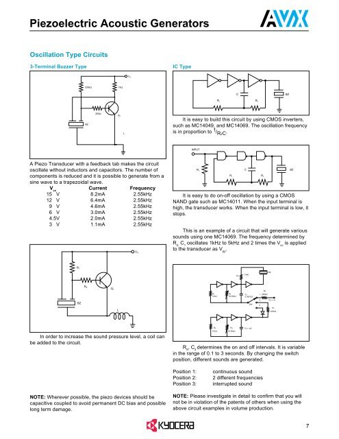
Oscillation Type Circuits<br />
3-Terminal Buzzer Type<br />
IC Type<br />
V cc<br />
330kΩ<br />
1kΩ<br />
C<br />
BZ<br />
R 1 R 2<br />
BZ<br />
20kΩ<br />
Q 1<br />
It is easy to build this circuit by using CMOS inverters,<br />
such as MC14049, and MC14069. The oscillation frequency<br />
is in proportion to 1 / R2C . R 1 R 2<br />
L<br />
INPUT<br />
A Piezo Transducer with a feedback tab makes the circuit<br />
oscillate without inductors and capacitors. The number of<br />
components is reduced and it is possible to generate from a<br />
sine wave to a trapezoidal wave.<br />
V cc<br />
Current Frequency<br />
155.V 8.2mA 2.55kHz<br />
125.V 6.4mA 2.55kHz<br />
595.V 4.6mA 2.55kHz<br />
565.V 3.0mA 2.55kHz<br />
54.5V 2.0mA 2.55kHz<br />
535.V 1.1mA 2.55kHz<br />
Vcc<br />
R 3<br />
It is easy to do on-off oscillation by using a CMOS<br />
NAND gate such as MC14011. When the input terminal is<br />
high, the transducer works. When the input terminal is low, it<br />
stops.<br />
This is an example of a circuit that will generate various<br />
sounds using one MC14069. The frequency determined by<br />
R 2,<br />
C 1<br />
oscillates 1kHz to 5kHz and 2 times the V cc<br />
is applied<br />
to the transducer as V pp<br />
.<br />
C<br />
BZ<br />
R1<br />
R3<br />
1.5kΩ<br />
BZ<br />
R 2<br />
Q1<br />
R6<br />
R1<br />
10kΩ<br />
R2<br />
30-50kΩ<br />
C1<br />
0.0067µF<br />
1 220kΩ<br />
BZ<br />
SW<br />
2<br />
3<br />
VCC = 9<br />
L<br />
R7<br />
220kΩ<br />
In order to increase the sound pressure level, a coil can<br />
be added to the circuit.<br />
R4<br />
10kΩ<br />
R5<br />
30-50kΩ<br />
+<br />
C2 = 1µF<br />
R 5<br />
, C 2<br />
determines the on and off intervals. It is variable<br />
in the range of 0.1 to 3 seconds. By changing the switch<br />
position, different sounds are generated.<br />
Position 1:<br />
Position 2:<br />
Position 3:<br />
continuous sound<br />
2 different frequencies<br />
interrupted sound<br />
NOTE: Wherever possible, the piezo devices should be<br />
capacitive coupled to avoid permanent DC bias and possible<br />
long term damage.<br />
NOTE: Please investigate in detail to confirm that you will<br />
not be in violation of the patents of others when using the<br />
above circuit examples in volume production.<br />
7


