
You also want an ePaper? Increase the reach of your titles
YUMPU automatically turns print PDFs into web optimized ePapers that Google loves.
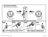
<strong>Closer</strong> Adjustment<br />
RIXSON FIREMARK<br />
LH<br />
ON<br />
HO<br />
TURN FULL<br />
OFF<br />
180°<br />
+ -<br />
BACKCHECK<br />
LATCH<br />
S LO W<br />
FRANKLIN PARK ILLINOIS<br />
DELAY ACTION<br />
CLOSING SPEED<br />
S LO W<br />
Closing speeds can be adjusted to suit local conditions and<br />
requirements. Label on closer face designates the purpose<br />
of each adjustment screw. Adjustments are for speed<br />
control.<br />
A. The Delay Action valve allows adjustment from full<br />
open to 65° closed position. (Optional)<br />
B. The Closing Speed valve allows adjustment from full<br />
open to 15° on units without the Delay Action feature.<br />
C. The Closing Speed valve allows adjustment from 65°<br />
to 15° closed position on closers with Delay Action<br />
feature.<br />
D. Latch valve allows adjustment from 15° to closed<br />
position.<br />
E. Important: Backcheck adjustment must be adjusted to<br />
vary resistance from light to firm at 60° of door open.<br />
RIXSON FIREMARK<br />
DELAY ACTION<br />
CLOSING SPEED<br />
S LO W<br />
This Set Screw Is On Selector Hold-open Types Only<br />
LATCH<br />
S LO W<br />
FRANKLIN PARK ILLINOIS<br />
+<br />
BACKCHECK<br />
RH<br />
Do not use Backcheck as deadstop. This is an intensity<br />
valve not speed control.<br />
15°<br />
CLOSED<br />
70°<br />
-<br />
OFF<br />
HO<br />
TURN FULL<br />
ON<br />
180°<br />
DELAYED ACTION<br />
If equipped<br />
PAGE 4<br />
®<br />
RIXSON<br />
ASSA ABLOY<br />
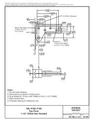
Template<br />
13/16<br />
3/4<br />
3/16 R.<br />
Bevel Edge<br />
of <strong>Door</strong><br />
1/8” in 2”<br />
Jamb<br />
2-1/16 R.<br />
2-1/16<br />
1-5/16<br />
Spindle<br />
Shoulder<br />
Collar<br />
1/8 Min. Clearance Required<br />
Between <strong>Door</strong> and Stop<br />
Arm<br />
3/4<br />
Floor Plate<br />
9-13/16 Cement Case<br />
9-7/8 Floor Plate<br />
Arm Bearing Washer<br />
Installation Instructions<br />
2700T (10-09)<br />
1-1/16<br />
Floor Plate<br />
5-7/8<br />
Cement<br />
Case<br />
5/16<br />
6-1/8<br />
Floor<br />
Plate<br />
4-1/16<br />
5/8 Min<br />
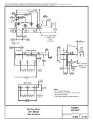
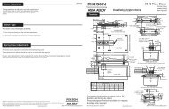
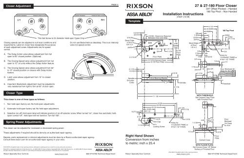
27 & 27-180 Floor <strong>Closer</strong><br />
3/4" Offset Pivoted – Handed<br />
3/8<br />
1-35/64<br />
25/64<br />
Jamb<br />
Bevel Edge<br />
of <strong>Door</strong><br />
1/8 in 2<br />
1/16<br />
5/8<br />
7/16<br />
3/4<br />
3/4<br />
3/4<br />
1-1/16<br />
CL<br />
180 Top Pivot – Non Handed<br />
4-1/4<br />
3-55/64<br />
2-45/64<br />
13/16<br />
3/4<br />
1/8 R.<br />
23/64<br />
45/64<br />
1-1/16<br />
3/4<br />
Holes for<br />
1/4-20x5/8" FHMS or<br />
#14x1-1/2" FHWS<br />
1/4 1/4<br />
3/16<br />
180 Top Pivot<br />
2<br />
<strong>Door</strong> Mortised "A"<br />
Deep for Arm "A"<br />
1/4 Threshold 5/8<br />
1/2 Threshold 3/8<br />
Threshold<br />
<strong>Closer</strong> Type<br />
This closer is one of three types as follows:<br />
11-1/8<br />
WITH THRESHOLD<br />
Set Cement Case Flush<br />
with Finished Floor<br />
1. Non hold-open factory set. No hold-open adjustments.<br />
2. Automatic hold-open factory set. No hold-open adjustment.<br />
3. Selective (on-off) hold-open label will indicate position of on-off selector screw. When turned “on”, closer has automatic holdopen:<br />
turned “off”, hold-open will not function. Turn full 180°.<br />
Spring Power Adjustments<br />
This closer can be adjusted for increased or decreased spring power.<br />
1/2 R.<br />
2-1/4<br />
3-3/8<br />
1/2<br />
6-1/4<br />
9-5/8<br />
9-1/8<br />
1/4 R.<br />
Arm Cap<br />
1-1/4 Arm<br />
Locking Screw<br />
3/8<br />
11/16<br />
1-3/16<br />
Holes for<br />
1/4-20x5/8" FHMS or<br />
#14x1-1/2" FHWS<br />
1-1/16<br />
3/4<br />
<strong>Door</strong><br />
Mortised<br />
3/4 Deep<br />
for Arm<br />
These adjustments if required should be done by an authorized repair agency.<br />
Repairs, parts replacement or internal adjustments must be done by a Rixson authorized repair agency.<br />
Consult www.rixson.com for an authorized repair agency in your area.<br />
Rixson® is a registered trademark of Yale Security Inc., an ASSA ABLOY Group company. Copyright© 2002, 2009, Yale Security Inc., an ASSA ABLOY Group company.<br />
All rights reserved. Reproduction in whole or in part without the express written permission of Yale Security Inc. is prohibited.<br />
RIXSON®<br />
ASSA ABLOY<br />
Right Hand Shown<br />
Conversion from inches<br />
to metric: inch x 25.4<br />
1/2<br />
Cement Case<br />
WITH FLOOR PLATE<br />
Set Cement Case 1/8" Below<br />
Surface of Finished Floor<br />
3/16<br />
Floor<br />
Plate<br />
Rixson Specialty <strong>Door</strong> Controls www.rixson.com 866-474-9766 Technical Department<br />
Rixson Specialty <strong>Door</strong> Controls<br />
www.rixson.com<br />
866-474-9766 Technical Department
PAGE 2<br />
PAGE 3<br />
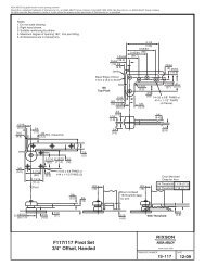
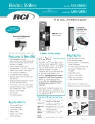
How To Determine<br />
Hand of <strong>Door</strong><br />
LH<br />
RH<br />
Face a door swinging open away from you. If it opens to the<br />
right, it is right hand. If it opens to the left, it is left hand.<br />
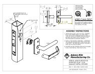
Top Pivot Jamb Portion<br />
Top Pivot <strong>Door</strong> Portion<br />
Intermediate<br />
(Side Jamb)<br />
Arm Cap<br />
Pivot<br />
Spindle Arm<br />
Knuckle<br />
RIGHT HAND installation<br />
IMPORTANT:<br />
Use plumb line to make<br />
sure that center line of<br />
top pivot pin lines up<br />
with center line of closer<br />
spindle.<br />
Arm Locking<br />
Screw<br />
4. Hang <strong>Door</strong><br />
4a<br />
Pins point down for<br />
RH closer<br />
Right Hand Shown<br />
Wrench<br />
CAUTION:<br />
<strong>Closer</strong> is shipped with Closing Speed valve<br />
down. DO NOT FORCE VALVE DOWN.<br />
A. Close down Latch Speed valve. Using wrench, turn<br />
spindle until wrench is parallel with center line of<br />
closer. (Illustration 4a)<br />
B. Insert arm bearing washer over spindle then set door<br />
on closer spindle. DO NOT FORCE DOOR CLOSED<br />
WHILE “CLOSING SPEED” VALVE IS TURNED<br />
DOWN.<br />
C. Push item 1 “top pivot pin” into place. Attach “cap”<br />
item 2. (Illustration 4b) CAP MUST BE TIGHTENED<br />
SECURELY.<br />
Installation Instructions<br />
4b<br />
D. Close door to 60° or more and turn Closing Speed<br />
valve screw counterclockwise. <strong>Door</strong> will then close.<br />
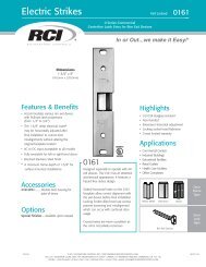
1. Locating <strong>Closer</strong><br />
For accurate installation see your dealer<br />
for a 185 Quickspotter Kit.<br />
<strong>Door</strong> Stop<br />
2. Install Cement Case in Floor<br />
LEVEL IN BOTH<br />
DIRECTIONS<br />
1<br />
2<br />
2<br />
1<br />
E. Open Closing Speed valve (counterclockwise) one<br />
turn. To increase (speed up) closing, open Latch<br />
Speed valve (ccw) one turn.<br />
F. If door drags at floor (or threshold, if used), raise<br />
door to desired clearance and insert one or more<br />
1/16” shims. (Illustration 4c) See M19 Installation<br />
sheet to lift door for shimming.<br />
<strong>Door</strong><br />
Jamb<br />
1/8” Minimum From<br />
Face of <strong>Door</strong> to <strong>Door</strong> Stop<br />
Right Hand <strong>Door</strong><br />
3/4” From Face<br />
of <strong>Door</strong> to C of Spindle<br />
L<br />
Spindle Position<br />
13/16” From Face of<br />
Jamb to C of Spindle<br />
L<br />
A. Measure 13/16” out from door jamb.<br />
A. For floor plate application: Cement case is set 1/8”<br />
(3.2mm) below floor level.<br />
B. For threshold application: Cement case is set flush with<br />
floor.<br />
C. Set cement case in floor and block in position.<br />
D. Case should be parallel with center line of door.<br />
E. CEMENT CASE SHOULD BE LEVEL. Place levels per<br />
Illustration.<br />
F. Grout in cement case with closer. Cement should not get<br />
between closer and case.<br />
4c<br />
Knuckle<br />
Arm Bearing<br />
Washer<br />
Spindle<br />
Shim snaps in between<br />
arm bearing washer<br />
and arm knuckle<br />
Arm Bearing<br />
Washer<br />
Flat sides should be<br />
parallel<br />
G. While working door back and forth TIGHTEN ARM<br />
LOCKING SCREW SECURELY with wrench<br />
furnished.<br />
H. Put arm cap on closer spindle and secure TIGHTLY<br />
with cap screw furnished.<br />
I. Adjust closing and latch speeds as required for<br />
proper closing.<br />
B. Allow 1/8” minimum clearance from door stop to door face.<br />
Measure door thickness. Add 3/4”.<br />
C. Where lines meet determines center line of closer.<br />
3. Install Top Pivot & <strong>Closer</strong> Arm<br />
Push shim into position<br />
with thumb or butt end or<br />
screwdriver<br />
A. Install top pivot in door per template.<br />
B. Install top pivot in frame per template.<br />
C. Center line of pivot should line up with center line of<br />
closer. Use plumb line as illustrated.<br />
D. If side pivot is used, see template for intermediate pivot.<br />
E. Install door closer arm in bottom of door per template.<br />
Rixson Specialty <strong>Door</strong> Controls www.rixson.com 866-474-9766 Technical Department<br />
Rixson Specialty <strong>Door</strong> Controls www.rixson.com 866-474-9766 Technical Department