CRL RETRACTABLE SCREEN DOOR - TechnologyLK.com
CRL RETRACTABLE SCREEN DOOR - TechnologyLK.com
CRL RETRACTABLE SCREEN DOOR - TechnologyLK.com

You also want an ePaper? Increase the reach of your titles
YUMPU automatically turns print PDFs into web optimized ePapers that Google loves.
C.R. LAURENCE CO., INC.<br />
<strong>CRL</strong> <strong>RETRACTABLE</strong> <strong>SCREEN</strong> <strong>DOOR</strong><br />
Installation Instructions<br />
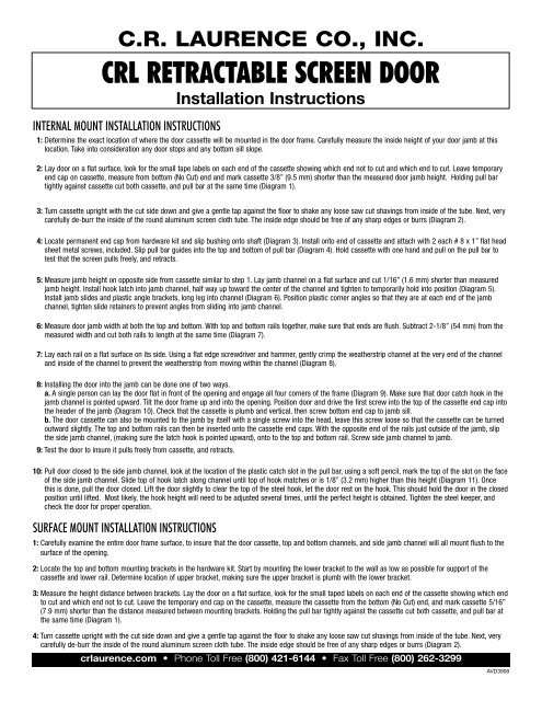
INTERNAL MOUNT INSTALLATION INSTRUCTIONS<br />
1: Determine the exact location of where the door cassette will be mounted in the door frame. Carefully measure the inside height of your door jamb at this<br />
location. Take into consideration any door stops and any bottom sill slope.<br />
2: Lay door on a flat surface, look for the small tape labels on each end of the cassette showing which end not to cut and which end to cut. Leave temporary<br />
end cap on cassette, measure from bottom (No Cut) end and mark cassette 3/8” (9.5 mm) shorter than the measured door jamb height. Holding pull bar<br />
tightly against cassette cut both cassette, and pull bar at the same time (Diagram 1).<br />
3: Turn cassette upright with the cut side down and give a gentle tap against the floor to shake any loose saw cut shavings from inside of the tube. Next, very<br />
carefully de-burr the inside of the round aluminum screen cloth tube. The inside edge should be free of any sharp edges or burrs (Diagram 2).<br />
4: Locate permanent end cap from hardware kit and slip bushing onto shaft (Diagram 3). Install onto end of cassette and attach with 2 each # 8 x 1” flat head<br />
sheet metal screws, included. Slip pull bar guides into the top and bottom of pull bar (Diagram 4). Hold cassette with one hand and pull on the pull bar to<br />
test that the screen pulls freely, and retracts.<br />
5: Measure jamb height on opposite side from cassette similar to step 1. Lay jamb channel on a flat surface and cut 1/16” (1.6 mm) shorter than measured<br />
jamb height. Install hook latch into jamb channel, half way up toward the center of the channel and tighten to temporarily hold into position (Diagram 5).<br />
Install jamb slides and plastic angle brackets, long leg into channel (Diagram 6). Position plastic corner angles so that they are at each end of the jamb<br />
channel, tighten slide retainers to prevent angles from sliding into jamb channel.<br />
6: Measure door jamb width at both the top and bottom. With top and bottom rails together, make sure that ends are flush. Subtract 2-1/8” (54 mm) from the<br />
measured width and cut both rails to length at the same time (Diagram 7).<br />
7: Lay each rail on a flat surface on its side. Using a flat edge screwdriver and hammer, gently crimp the weatherstrip channel at the very end of the channel<br />
and inside of the channel to prevent the weatherstrip from moving within the channel (Diagram 8).<br />
8: Installing the door into the jamb can be done one of two ways.<br />
a. A single person can lay the door flat in front of the opening and engage all four corners of the frame (Diagram 9). Make sure that door catch hook in the<br />
jamb channel is pointed upward. Tilt the door frame up and into the opening. Position door and drive the first screw into the top of the cassette end cap into<br />
the header of the jamb (Diagram 10). Check that the cassette is plumb and vertical, then screw bottom end cap to jamb sill.<br />
b. The door cassette can also be mounted to the jamb by itself with a single screw into the head, leave this screw loose so that the cassette can be turned<br />
outward slightly. The top and bottom rails can then be inserted onto the cassette end caps. With the opposite end of the rails just outside of the jamb, slip<br />
the side jamb channel, (making sure the latch hook is pointed upward), onto to the top and bottom rail. Screw side jamb channel to jamb.<br />
9: Test the door to insure it pulls freely from cassette, and retracts.<br />
10: Pull door closed to the side jamb channel, look at the location of the plastic catch slot in the pull bar, using a soft pencil, mark the top of the slot on the face<br />
of the side jamb channel. Slide top of hook latch along channel until top of hook matches or is 1/8” (3.2 mm) higher than this height (Diagram 11). Once<br />
this is done, pull the door closed. Lift the door slightly to clear the top of the steel hook, let the door rest on the hook. This should hold the door in the closed<br />
position until lifted. Most likely, the hook height will need to be adjusted several times, until the perfect height is obtained. Tighten the steel keeper, and<br />
check the door for proper operation.<br />
SURFACE MOUNT INSTALLATION INSTRUCTIONS<br />
1: Carefully examine the entire door frame surface, to insure that the door cassette, top and bottom channels, and side jamb channel will all mount flush to the<br />
surface of the opening.<br />
2: Locate the top and bottom mounting brackets in the hardware kit. Start by mounting the lower bracket to the wall as low as possible for support of the<br />
cassette and lower rail. Determine location of upper bracket, making sure the upper bracket is plumb with the lower bracket.<br />
3: Measure the height distance between brackets. Lay the door on a flat surface, look for the small taped labels on each end of the cassette showing which end<br />
to cut and which end not to cut. Leave the temporary end cap on the cassette, measure the cassette from the bottom (No Cut) end, and mark cassette 5/16”<br />
(7.9 mm) shorter than the distance measured between mounting brackets. Holding the pull bar tightly against the cassette cut both cassette, and pull bar at<br />
the same time (Diagram 1).<br />
4: Turn cassette upright with the cut side down and give a gentle tap against the floor to shake any loose saw cut shavings from inside of the tube. Next, very<br />
carefully de-burr the inside of the round aluminum screen cloth tube. The inside edge should be free of any sharp edges or burrs (Diagram 2).<br />
crlaurence.<strong>com</strong> • Phone Toll Free (800) 421-6144 • Fax Toll Free (800) 262-3299<br />
AVD3908
5: Locate the permanent end cap from the hardware kit and slip bushing onto shaft (as shown in diagram 3). Install onto end of cassette and attach with 2<br />
each # 8 x 1” flat head sheet metal screws, included. Slip pull bar guides into the top and bottom of pull bar (Diagram 4). Hold cassette with one hand and<br />
pull on the pull bar to test that the screen pulls freely, and retracts.<br />
6: Measure overall length of assembled cassette; lay the side jamb channel on a flat surface and cut to the same length as the cassette.<br />
7: Drilling the mounting holes on the side jamb channel is a two step process. First, a few inches in from either end of the channel, drill a 1/8” (3.2 mm)<br />
diameter pilot hole through both legs of the channel. Second, drill a 5/16” (7.9 mm) diameter hole through one leg only. This larger outer hole is to allow a<br />
screw driver shank to reach the head of the mounting screw. Repeat this process on the opposite end of the channel and again in the center of the channel<br />
length (Diagram 12).<br />
8: Install steel hook latch (hook in the up position), into jamb channel, side toward the center of the channel and tighten to temporarily hold into position<br />
(Diagram 5). Install jamb slides and plastic angle brackets, long leg into channel (Diagram 6). Position plastic corner angles so that they are at each end of<br />
the jamb channel, tighten slide retainers to prevent angles from sliding into jamb channel.<br />
9: Mount the side jamb channel onto the surface of the door opening, across from the cassette; making sure that channel is parallel and plumb with the<br />
cassette.<br />
10: Measure the width of the opening from the outer edge of the cassette to the outer edge of the side jamb channel. Make this measurement at both the top<br />
and bottom of the opening. With top and bottom rails together, make sure that ends are flush (Diagram 7). Subtract 2-1/8” (54 mm) from the measured<br />
width and cut both rails to length at the same time.<br />
11: Lay each rail on a flat surface on its side. Using a flat edge screwdriver and hammer, gently crimp the weatherstrip groove at the very end of the channel<br />
and inside of the channel to prevent the weatherstrip from moving within the groove (Diagram 8).<br />
12: Slip the top and bottom rails onto the cassette and side jamb channels, engaging the plastic angles at the ends of the channel. Depending on mounting<br />
conditions, it may be necessary to drill mounting screw holes as described in step # 7.<br />
13: Carefully examine how much support the bottom channel has on the door threshold. Depending on several variables including slope, it may be necessary<br />
to shim the channel, for additional support.<br />
14: Test the door to insure it pulls freely from cassette, and retracts.<br />
15: Pull door closed to the side jamb channel, look at the location of the plastic catch slot in the pull bar, using a soft pencil, mark the top of the slot on the face<br />
of the side jamb channel. Slide top of hook latch along channel until top of hook matches or is 1/8” (3.2 mm) higher than this height (Diagram 11). Once<br />
this is done, pull the door closed. Lift the door slightly to clear the top of the steel hook, let the door rest on the hook. This should hold the door in the closed<br />
position until lifted. Most likely, the hook height will need to be adjusted several times, until the perfect height is obtained. Tighten the steel keeper, and<br />
check the door for proper operation.<br />
16: Snap screw-hole plugs into the holes in the side jamb channel and top and bottom rail where necessary to finish the installation.<br />
FRENCH <strong>DOOR</strong> INSTALLATION INSTRUCTIONS (Double Door Installations Requires Two Single Door Kits)<br />
1: Determine if door will be mounted internally (within the door jamb), or on the surface. Read the installation instructions for whichever single door install<br />
instructions apply, and then follow these additional steps to <strong>com</strong>plete the installation for two doors mounted together. Note: The side jamb channel is not<br />
needed for French Door installations.<br />
2: To determine top and bottom rail length, first mount both door cassettes, and measure the overall width at the bottom, (from outer edge of each cassette).<br />
Align both bottom rails together, making sure that the ends are flush so that both rails can be cut at the same time. Take the overall width and divide by 2,<br />
and then deduct 2-1/8” (54 mm). Mark the channels with a soft pencil and cut to length. Follow this step for cutting the top channels as well.<br />
3: Locate the plastic double door catch inside of the hardware kit (Diagram 13). Lay both bottom channels end to end, and slide the door catch into the<br />
weatherstrip groove where the two channels <strong>com</strong>e together. Center the catch so that half the catch engages both channels. On either side of the door catch,<br />
crimp the weatherstrip groove to stake the catch into the center of the door opening. Note: If using pliers, take care not to let the pliers mare or scratch the<br />
outer surface of the top and bottom rails. At the opposite end of the channels, snip the excess weatherstrip from the channel and crimp the weatherstrip<br />
groove as described in the single door instructions (Diagram 8).<br />
4: Follow the procedure above for the top rails, making sure that the door catch is on the same surface as the catch below. If the catch is mounted on the outer<br />
side of the bottom rails, it also needs to be mounted on the outer side of the top rails.<br />
5: Both doors should pull freely into the center of the opening until each door engages the top and bottom catches. To unlock the doors from the catch, just give<br />
a slight twist on the handle to disengage the catch.<br />
crlaurence.<strong>com</strong> • Phone Toll Free (800) 421-6144 • Fax Toll Free (800) 262-3299
Diagram 1 - Cutting Cassette and Pull Bar Diagram 2 - De-burring cut Cassette Diagram 3 - Installing End Cap<br />
Diagram 4 - Installing Pull Bar Guides Diagram 5 - Installing Hook Latch Diagram 6 - Installing Plastic Angle Brackets<br />
Diagram 7 - Cutting Top and Bottom Rails<br />
Diagram 8 - Crimping Weatherstrip Channel<br />
Diagram 9 - Engage all Four<br />
Corners of the Frame<br />
Diagram 10 - Attaching Top into Header Diagram 11 - Adjusting Plastic Hook Latch Diagram 12 - Prepping Side Jambs for Surface<br />
Mount Installations<br />
Diagram 13 - Attaching Bottom Channels with Double Door Catch<br />
crlaurence.<strong>com</strong> • Phone Toll Free (800) 421-6144 • Fax Toll Free (800) 262-3299
<strong>CRL</strong> <strong>RETRACTABLE</strong> <strong>SCREEN</strong> <strong>DOOR</strong> PARTS LIST<br />
E<br />
F<br />
G<br />
J<br />
H<br />
I<br />
A<br />
B<br />
C<br />
D<br />
A. Cassette<br />
B. Side Jamb Channel<br />
C. Top and Bottom Rails<br />
D. Handle<br />
E. End Cap<br />
F. Corner Angles<br />
G. Surface Mount Brackets<br />
H. Pull Bar Guides<br />
I. Double Door Catch<br />
J. Single Door Catch