Operations Manual - PV Powered
Operations Manual - PV Powered
Operations Manual - PV Powered

You also want an ePaper? Increase the reach of your titles
YUMPU automatically turns print PDFs into web optimized ePapers that Google loves.
<strong>PV</strong> Grid-tied Residential Inverters<br />
INSTALLATION & OPERATION MANUAL<br />
97-600100-01-A02
Preface<br />
<strong>PV</strong> <strong>Powered</strong><br />
<strong>PV</strong> <strong>Powered</strong> designs, manufactures, and markets the solar power industry’s most reliable<br />
photovoltaic solar inverter solutions. We’ve assembled a highly experienced solar power<br />
electronics design team. Our vision is to spur the widespread adoption and success of solar<br />
power, by assisting our distributors, dealers and installers in this dynamic market while<br />
ensuring that our products are the best supported, easiest to install, and most reliable solar<br />
inverters in the industry. Our innovative approach to performance monitoring provides<br />
secure and easy access to system performance and inverter status over the Internet.<br />
PREFACE<br />
Contact Information<br />
<strong>PV</strong> <strong>Powered</strong>, Inc.<br />
PO Box 7348<br />
Bend, OR 97708<br />
Tel: 541-312-3832<br />
Technical Support: 1-877-312-3832<br />
Fax: 541-383-2348<br />
www.pvpowered.com<br />
email: support@pvpowered.com<br />
Document Copyright<br />
<strong>PV</strong> <strong>Powered</strong> Grid-tied Inverters Installation and Operation <strong>Manual</strong> ©2009 <strong>PV</strong> <strong>Powered</strong>.<br />
All rights reserved. This manual may not be reproduced or distributed without written<br />
permission from <strong>PV</strong> <strong>Powered</strong>.<br />
i
Safety Information and Conventions<br />
Designation of Danger, Warning and Caution<br />
!<br />
!<br />
!<br />
DANGER<br />
The Danger statement is used to inform the installer/operator of a situation<br />
requiring the utmost attention. Failure to heed this warning will result in<br />
serious injury or death to personnel and destruction of equipment.<br />
WARNING<br />
The Warning statement is used to inform the installer/operator of a situation<br />
requiring serious attention. Failure to heed this warning may result in serious<br />
injury or death to personnel and destruction of equipment.<br />
CAUTION<br />
The Caution statement is used to inform the installer/operator of a situation<br />
requiring attention. Failure to heed this Caution may result in injury to<br />
personnel and damage<br />
to equipment.<br />
Revisions<br />
For applicability of technical information with your specific product, contact <strong>PV</strong> <strong>Powered</strong><br />
Customer Service and Technical Support at support@pvpowered.com.<br />
Certifications<br />
UL 1741<br />
IEEE 1547<br />
FCC Class A & B<br />
CEC Efficiency Testing<br />
ii
Grid-tied Residential Inverters<br />
Installation and Operation <strong>Manual</strong><br />
Acronyms and Abbreviations<br />
AC Alternating Current<br />
ANSI American National Standards Institute<br />
AWG American Wire Gage<br />
CEC California Energy Commission<br />
CPU Controlled Processing Unit<br />
DC Direct Current<br />
EGC Equipment Grounding Conductor<br />
FCC Federal Communications Commission (US)<br />
GEC Grounding Electrode Conductor<br />
GFI Ground Fault Interrupt<br />
IEEE Institute of Electrical and Electronics Engineers<br />
LED Light-Emitting Diode<br />
LOTO Lockout Tagout<br />
LP Low Power<br />
MPPT Maximum Power Point Tracking<br />
NEMA National Electrical Manufacturers Association<br />
NEC National Electric Code<br />
NFPA National Fire Protection Association<br />
Nm A unit of torque<br />
PLL Phase Lock Loop<br />
PPE Personal Protective Equipment<br />
<strong>PV</strong> Photovoltaic<br />
STC Standard Test Condition<br />
UL Underwriters Laboratory<br />
VAC Voltage Alternating Current<br />
VDC Voltage Direct Current<br />
VFD Vacuum Fluorescent Display<br />
VOC Voltage Open Circuit<br />
VOC_TC Voltage Open Circuit, Temperature Coefficient<br />
iii
Table of Contents<br />
Preface...................................................................................................................................i<br />
Safety Information and Conventions.................................................................................. ii<br />
Acronyms and Abbreviations............................................................................................. iii<br />
1. Introduction and Safety....................................................................................................1<br />
1.1 Introduction.............................................................................................................1<br />
1.2 General Safety.........................................................................................................1<br />
1.3 FCC Compliance.....................................................................................................2<br />
2. Planning...........................................................................................................................3<br />
2.1 Selecting a Location for the Inverter.......................................................................3<br />
2.2 Guidelines for Mounting the Inverter .....................................................................3<br />
3. Installation........................................................................................................................5<br />
3.1 Mounting and Anchoring the Inverter.....................................................................5<br />
3.2 Electrical Connections.............................................................................................7<br />
4. <strong>Operations</strong>......................................................................................................................17<br />
4.1 Start up Procedures...............................................................................................17<br />
4.2 Inverter Front Panel Status Indicators...................................................................17<br />
5. Troubleshooting.............................................................................................................20<br />
5.1 LED Status............................................................................................................20<br />
5.2 Displayed Fault Codes..........................................................................................21<br />
5.3 Fault Codes............................................................................................................23<br />
Appendix A - Specifications...............................................................................................24<br />
Appendix B - Dimensions..................................................................................................28<br />
B.1 Schematics for <strong>PV</strong>P1100W, <strong>PV</strong>P2000W, <strong>PV</strong>P2500W, <strong>PV</strong>P2800W,<br />
<strong>PV</strong>P3000W, and <strong>PV</strong>P3500W Inverter Cabinet.....................................................28<br />
B.2 Schematics for <strong>PV</strong>P4600W, <strong>PV</strong>P4800W, and <strong>PV</strong>P5200W Inverter Cabinet.......29<br />
Limited Warranty...............................................................................................................31<br />
Return Procedure................................................................................................................33<br />
Index...................................................................................................................................34<br />
TABLE OF<br />
CONTENTS<br />
iv
List of Figures and Tables<br />
Figure 2-1 View of the Inverter’s Interior Components......................................................4<br />
Figure 3-1 Small Mounting Bracket....................................................................................5<br />
Figure 3-2 Large Mounting Bracket....................................................................................6<br />
Figure 3-3 Inside Screw - Below the Power Board.............................................................6<br />
Figure 3-4 Inverter and <strong>PV</strong> System Disconnectwith Mounting Bracket in Place...............7<br />
Table 3-1 Required Branch Circuit Protection...................................................................8<br />
Table 3-2 Inverter Voltage Frequency Limits.....................................................................8<br />
Figure 3-5 Communications, AC and DC Ports...................................................................9<br />
Table 3-3 Grounding Electrode Sizing.............................................................................10<br />
Figure 3-6 System Block Diagram Showing Single-Point Ground..................................11<br />
Figure 3-7 Ground Fault Message.....................................................................................12<br />
Figure 3-8 AC and <strong>PV</strong> Grounding.....................................................................................12<br />
Figure 3-9 AC Wiring for the Line 1, Line 2 and Ground Conductors.............................13<br />
Table 3-4 <strong>PV</strong> Open Circuit Voltages................................................................................14<br />
Figure 3-10 Positive and Negative GFI Jumpers..............................................................15<br />
Figure 3-11 Power Board Connections.............................................................................16<br />
Figure 4-1 Normal Startup Screens...................................................................................19<br />
Figure 4-2 Running Screens..............................................................................................19<br />
Figure 5-1 Faulted.............................................................................................................21<br />
Figure 5-2 Starting Up From a Faulted State....................................................................21<br />
Figure 5-3 AC Voltage High/DC Voltage Low Fault.........................................................22<br />
Figure 5-4 Power Low Fault.............................................................................................22<br />
Table 5-1 Fault Codes........................................................................................................23<br />
Table A-1 <strong>PV</strong>P1100 through <strong>PV</strong>P2800 Specifications......................................................24<br />
Table A-1 (continued) <strong>PV</strong>P3000 through <strong>PV</strong>P5200 Specifications...................................25<br />
Table A-2 Abnormal Specifications...................................................................................26<br />
Figure B-1 Side and Front Views of <strong>PV</strong>P1100W, <strong>PV</strong>P2000W, <strong>PV</strong>P2500W,<br />
<strong>PV</strong>P2800W, <strong>PV</strong>P3000W, and <strong>PV</strong>P3500W Inverter Cabinet.................................27<br />
Figure B-2 Back and Bottom Views of <strong>PV</strong>P1100W, <strong>PV</strong>P2000W, <strong>PV</strong>P2500W,<br />
<strong>PV</strong>P2800W, <strong>PV</strong>P3000W, and <strong>PV</strong>P3500W Inverter Cabinet.................................28<br />
Figure B-3 Side and Front Views of the <strong>PV</strong>P4600W, <strong>PV</strong>P4800W,<br />
and <strong>PV</strong>P5200W Inverter Cabinet..........................................................................29<br />
Figure B-4 Back and Bottom Views of the <strong>PV</strong>P4600W, <strong>PV</strong>P4800W,<br />
and <strong>PV</strong>P5200W Inverter Cabinet..........................................................................30<br />
v
1. Introduction and Safety<br />
1.1<br />
1.2<br />
Introduction<br />
The <strong>PV</strong> <strong>Powered</strong> Grid-Tied Inverter is a utility interactive inverter for photovoltaic<br />
(<strong>PV</strong>) systems.<br />
The inverter is tied to an electrical source provided by the local utility company as well as<br />
the <strong>PV</strong> system. The inverter contains everything needed to convert the DC energy generated<br />
by the <strong>PV</strong> array(s) into AC energy required to power a house.<br />
This manual provides information necessary for the successful installation and use of the<br />
<strong>PV</strong> <strong>Powered</strong> Grid-Tied Inverter.<br />
General Safety<br />
IMPORTANT SAFETY INSTRUCTIONS: This product has been engineered and<br />
manufactured to ensure your personal safety. Improper use may result in potential electrical<br />
shock or burns. Read and follow all instructions for installation, use and servicing of this<br />
product. Read all safety warnings before installing or operating the inverter.<br />
NOTE: A locking tab has been designed into the <strong>PV</strong> <strong>Powered</strong> Grid-tied Inverter. Locking<br />
the inverter is the sole responsibility of the end user. Secure the lid to prevent<br />
unauthorized access or damage to the inverter.<br />
SAVE THESE INSTRUCTIONS: This manual contains important instructions for the <strong>PV</strong><br />
<strong>Powered</strong> Grid-Tied Inverter that must be followed during installation of the <strong>PV</strong> <strong>Powered</strong><br />
Grid-Tied Inverter.<br />
INSTRUCTIONS IMPORTANTES CONCERNANT LA SECURITÉ CONSERVER CES<br />
INSTRUCTIONS. CETTE NOTICE CONTIENT DES INSTRUCTIONS IMPORTANTES<br />
CONCERNANT LA SÉCURITÉ.<br />
INTRODUCTION<br />
& SAFETY<br />
!<br />
CAUTION<br />
• All electrical installations should be done in accordance with local<br />
electrical codes and the National Electrical Code (NEC), ANSI/NFPA 70.<br />
• Before connecting the inverter to the electrical utility grid, your utility<br />
company must grant approval. Only qualified electricians should make the<br />
connection.<br />
• When exposed to light, <strong>PV</strong> arrays form electrical energy that creates a<br />
potentially hazardous condition. To avoid this, completely cover the surface<br />
of all <strong>PV</strong> arrays with opaque (dark) material before wiring them.<br />
• The inverter contains no user-serviceable parts. Refer maintenance to<br />
qualified service personnel.<br />
1
1.3<br />
FCC Compliance<br />
The <strong>PV</strong> <strong>Powered</strong> Grid-Tied Inverters have been tested and found to pass FCC<br />
Class B radio interference standards with proper installation of the inverter. This<br />
is not a guarantee that there will be no interference at every installation. If you<br />
notice interference at your installation, try the following potential solutions:<br />
• Move or re-orient the affected device.<br />
• Increase the distance between the devices.<br />
• Connect the device to a different AC circuit.<br />
!<br />
CAUTION<br />
Read all safety warnings and instructions before installing or operating the<br />
inverter.<br />
2
2. Planning<br />
2.1<br />
2.2<br />
Selecting a Location for the Inverter<br />
When choosing a location for the inverter, consider the following criteria:<br />
• The inverter is suitable for both indoor and outdoor installation; the inverter enclosure<br />
has a NEMA 3R rating.<br />
• The optimum location of the inverter is outside, shielded from direct exposure to sunlight<br />
(i.e. not on the south facing side of the building).<br />
• The heat sink temperature can exceed 158°F (70°C). The inverter should be installed so<br />
that people can not touch the top of the unit.<br />
• The inverter is designed and tested to produce maximum continuous output power<br />
within the ambient temperature range of -15°F to 105°F (-25°C to 40°C).<br />
Location and Clearances<br />
The following clearances are recommended for proper placement of the inverter:<br />
• A minimum of 36 inches between the bottom of the inverter box and the ground.<br />
• A minimum of 12 inches above the heat sink.<br />
• Approximately one half inch of width clearance on the right and left sides of the inverter<br />
cabinet.<br />
Visibility of the operating LEDs and display located at the top front of the inverter box<br />
should also be considered. Refer to Figure 2-1 for these within the inverter’s box.<br />
If the inverter is installed in an enclosed space, adequate ventilation must be provided.<br />
Guidelines for Mounting the Inverter<br />
The inverter should be mounted vertically to a flat, solid surface such as strut, concrete, or<br />
wood siding. It should be located near the <strong>PV</strong> arrays to minimize the DC conductor length.<br />
The bracket and paper mounting template provided make mounting the inverter quick and<br />
simple.<br />
The small bracket:<br />
• Has a vertical row of screw holes down the center and is designed for a single-stud<br />
mount. Refer to Figure 3-2.<br />
The large bracket:<br />
• Has two top screw holes at either end of the large bracket, 16” apart which are designed<br />
to match standard stud spacing. Refer to Figure 3-1.<br />
The inverter also has an internal mounting screw. Refer to Figure 2-1 for the location of this<br />
screw.<br />
PLANNING<br />
3
!<br />
WARNING<br />
Before drilling holes to mount the inverter, verify that there are no electrical<br />
wires or plumbing in the area.<br />
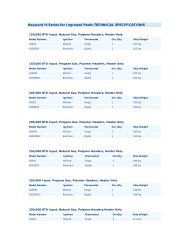
Display<br />
Control Board<br />
with LED Lights<br />
Transformer<br />
Inductor<br />
Power Board<br />
GFI Fuse Port<br />
Mounting Screw<br />
Figure 2-1 View of the Inverter’s Interior Components<br />
4
3. Installation<br />
3.1<br />
Mounting and Anchoring the Inverter<br />
After you have determined a suitable location for the inverter, the bracket is anchored to the<br />
wall stud(s).<br />
Models <strong>PV</strong>P1100, <strong>PV</strong>P2000, <strong>PV</strong>P2500, <strong>PV</strong>P2800, <strong>PV</strong>P3000 and <strong>PV</strong>P3500<br />
1. Locate a wall stud in the desired location and align the mounting bracket or paper<br />
mounting template with the vertical row of screw holes over it for a single-stud mount.<br />
Mark the mounting holes ensuring holes C through F are directly over the single stud.<br />
2. VERIFY THE BRACKET IS LEVEL. Ensure points C through F are aligned with the<br />
wall stud. Drill 1/8” pilot holes for the screws.<br />
• Use heavy-duty 1/4” x 2” coarse thread lag screws to secure points C, D and F.<br />
• Use an 1/8” screw (and anchor if necessary) to secure point E. Refer to Figure 3-1.<br />
INSTALLATION<br />
A<br />
C<br />
B<br />
D<br />
E<br />
F<br />
Figure 3-1 Small Mounting Bracket<br />
3.<br />
4.<br />
5.<br />
6.<br />
Carefully hang the inverter on the upper part of the bracket. The hooks located at the<br />
rear of the inverter should hang over the bracket.<br />
Verify the inverter is level.<br />
Remove the front lid of the inverter by unscrewing the two cover screws located at the<br />
bottom perimeter of the inverter.<br />
Locate the inverter mounting hole below the power board (see Figure 3-3). Insert the<br />
mounting screw through the inverter and tighten securely.<br />
5
Models <strong>PV</strong>P4600, <strong>PV</strong>P4800 and <strong>PV</strong>P5200<br />
1. Locate the wall studs in the desired location and align the mounting bracket or paper<br />
mounting template over the studs. Mark the mounting holes. Ensure that locations A and<br />
B (see Figure 3-2) are aligned over two wall studs.<br />
2. VERIFY THE BRACKET IS LEVEL. Ensure points A and B are aligned with the wall<br />
studs. Drill 1/8” pilot holes for the screws.<br />
• Use heavy-duty 1/4” x 2” coarse thread lag screws to secure points A and B<br />
to the wall.<br />
• Use an 1/8” screw (and anchor if necessary) to secure point C.<br />
A<br />
B<br />
C<br />
Figure 3-2 Large Mounting Bracket<br />
3.<br />
4.<br />
5.<br />
6.<br />
Carefully hang the inverter on the upper part of the bracket. The hooks located at the<br />
rear of the inverter should hang over the bracket.<br />
Verify the inverter is level.<br />
Remove the front lid of the inverter by unscrewing the four screws located around the<br />
front perimeter of the inverter.<br />
Locate the inverter mounting hole below the power board. Refer to Figure 3-3.<br />
Insert the mounting screw through the inverter and tighten securely.<br />
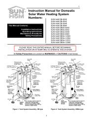
Figure 3-3 Inside Screw - Below the Power Board<br />
6
Grid-tied Residential Inverters<br />
Installation and Operation <strong>Manual</strong><br />
GFI fuse<br />
external<br />
access port<br />
Figure 3-4 Inverter and <strong>PV</strong> System Disconnect<br />
with Mounting Bracket in Place<br />
NOTE: Leave the inverter lid off to allow for completing the electrical connections<br />
described in the next section, Electrical Connections.<br />
3.2<br />
Electrical Connections<br />
!<br />
CAUTION<br />
The National Electrical Code (NEC) requires that the inverter be connected<br />
to a dedicated circuit with no other outlets or devices connected to the same<br />
circuit. See NEC Section 690-64(b)(1). The NEC also places limitations on the<br />
size of the inverter and the manner in which it is connected to the utility grid.<br />
See NEC Section 690-64(b)(2).<br />
To reduce the risk of fire, connect the inverter to the appropriate size breaker<br />
(see Table 3-1 for required branch circuit protection). Maximum branch-circuit<br />
over-current protection is calculated in accordance with the National Electrical<br />
Code (NEC), ANSI/NFPA 70.<br />
7
Inverter Model<br />
<strong>PV</strong>P1100<br />
<strong>PV</strong>P2000<br />
<strong>PV</strong>P2500<br />
<strong>PV</strong>P2800<br />
<strong>PV</strong>P3000<br />
<strong>PV</strong>P3500<br />
<strong>PV</strong>P4600<br />
<strong>PV</strong>P4800<br />
<strong>PV</strong>P5200<br />
Circuit Breaker<br />
Required<br />
1 pole 15A<br />
2 pole 15A<br />
2 pole 20A<br />
2 pole 20A<br />
2 pole 20A<br />
2 pole 20A<br />
2 pole 30A<br />
2 pole 30A<br />
2 pole 30A<br />
Table 3-1 Required Branch Circuit Protection<br />
Inverter Voltage and Frequency Limits<br />
The inverter is factory calibrated to the voltage and frequency limits specified in Table<br />
3-2. This voltage range can be adjusted by <strong>PV</strong> <strong>Powered</strong> field technicians under special<br />
circumstances.<br />
Condition<br />
Factory<br />
Setting<br />
Adjustable Range<br />
(VAC) Models 2000,<br />
2500, 2800, 3000, 3500,<br />
4600, 4800, 5200<br />
Adjustable Range<br />
(VAC) Models<br />
1100<br />
Maximum Trip<br />
Time(s)<br />
Voltage phase high 132.0 132.0 - 142.0 132.0 - 142.0 < 1 second<br />
Voltage phase low 105.6 95.6 - 105.6 95.6 - 105.6 < 2 seconds<br />
Voltage phase fast high 144.0 144.0 - 156.0 144.0 - 156.0 < 160ms<br />
Voltage phase fast low 60.0 < 60.0 < 60.0 < 160ms<br />
Voltage high line to line 264.0<br />
(240V inverters)<br />
Voltage low line to line 211.0<br />
(240V inverters)<br />
Voltage high line to line 228.8<br />
(208V inverters)<br />
Voltage low line to line 183.0<br />
(208V inverters)<br />
Line frequency low 59.3 Hz n/a < 160ms<br />
Line frequency high 60.5 Hz n/a < 160ms<br />
Table 3-2 Inverter Voltage Frequency Limits<br />
NOTE: Do not proceed with making the inverter’s electrical connections until it is<br />
properly mounted.<br />
8
Grid-tied Residential Inverters<br />
Installation and Operation <strong>Manual</strong><br />
!<br />
WARNING<br />
Electrical connections must be completed in accordance with local electrical<br />
codes and the National Electrical Code (NEC), ANSI/NFPA 70. Use 12 AWG<br />
minimum, 90°C copper wire for all inverter electrical connections. Voltage<br />
drop as well as other considerations may dictate using larger wire sizes.<br />
NOTE: To avoid an increase in AC voltage level, which may lead to nuisance faults, <strong>PV</strong><br />
<strong>Powered</strong> recommends sizing the conductor for a drop of less than 2%.<br />
!<br />
!<br />
WARNING<br />
Ensure the breaker in the main utility service panel is switched OFF before<br />
wiring the inverter. This breaker should be switched ON only after all wiring<br />
has been completed as described in this manual.<br />
WARNING<br />
Follow the order listed below to wire the inverter. Failure to do so may result<br />
in hazardous voltages or disconnection of contacts.<br />
IMPORTANT: When mounting the inverter outside, use rain-tight or wet-location conduit<br />
hubs that comply with the requirements in the Standard for Fittings for Conduit and Outlet<br />
Boxes, UL 514B.<br />
NOTE: Terminal connections for the inverter are located inside the inverter on the circuit<br />
board at the bottom of the cabinet. The AC and DC terminals accept wires up to<br />
6 AWG.<br />
!<br />
CAUTION<br />
The DC/AC input and output circuits are isolated from the enclosure. The <strong>PV</strong><br />
equipment grounding conductor (EGC), where required by Sections 690-41,<br />
690-42, and 690-43 of the National Electric Code (NEC), ANSI/NFPA 70,<br />
is the responsibility of the installer. Failure to properly install the ground<br />
conductor for the <strong>PV</strong> equipment can result in exposed metallic surfaces<br />
becoming energized to the full potential of the <strong>PV</strong> array.<br />
GFI Fuse External<br />
Access Port<br />
Drainage Port<br />
Figure 3-5 Communications, AC and DC Ports<br />
9
Separation of Circuits<br />
The lower part of the inverter circuit board is divided into three sections:<br />
1. The left side is dedicated to the low voltage DC communications (<strong>PV</strong>M1010 data monitoring<br />
module).<br />
2. The center is dedicated to the AC.<br />
3. The right side is dedicated to the DC.<br />
Each section has one to three knockouts. UL 1741 requires a straight run of conductor, with<br />
no loops or crossover to the other circuits (sections) and low voltage versus high voltage in<br />
each section (see Figure 3-5).<br />
1.<br />
2.<br />
3.<br />
Left knockouts (up to the divider) are for low voltage communications only (<strong>PV</strong>M1010<br />
Data Monitoring Module).<br />
Center knockouts are for AC.<br />
Right knockouts are for DC.<br />
Grounding<br />
A single-point ground conductor connection is located in the lower right-hand side of the<br />
inverter cabinet. This is where the DC grounding electrode conductor (GEC) is terminated.<br />
The AC equipment grounding conductor (EGC) is terminated next to the Line 1 and Line 2<br />
connections on the circuit board.<br />
The grounding lug is attached to the cabinet with a 10-32 bolt. The equipment ground<br />
connector or grounding lug is provided, utilizing the <strong>PV</strong> equipment and AC ground<br />
conductor. This is the only place the <strong>PV</strong> ground should be connected to the inverter.<br />
• Do not tie the GEC to the <strong>PV</strong> array positive or negative. This would defeat the<br />
<strong>PV</strong> ground fault interrupt protection circuit. Refer to Figure 3-8 for illustrated<br />
information.<br />
• See Table 3-3 for appropriate sizing of the grounding electrode conductor. Use the<br />
maximum current AC or DC - whichever is larger - and multiply it by 1.25 to get the<br />
maximum current rating per NEC 690.<br />
Maximum<br />
Current Rating<br />
Minimum Size of Grounding<br />
Electrode Conductor AWG<br />
Copper Aluminum<br />
Copper Clad<br />
15 8 6<br />
20 8 6<br />
30 8 6<br />
40 8 6<br />
60 8 6<br />
Table 3-3 Grounding Electrode Sizing<br />
10
Grid-tied Residential Inverters<br />
Installation and Operation <strong>Manual</strong><br />
Figure 3-6 is a schematic representation of the <strong>PV</strong> <strong>Powered</strong> single-point grounding. The<br />
front lid is grounded through the cover’s mounting screws.<br />
Figure 3-6 System Block Diagram Showing Single-Point Ground<br />
Ground Fault Interruption Circuit (GFI)<br />
The purpose of the GFI circuit is to detect a ground fault current, interrupt the flow of a fault<br />
current, and provide an indication of the fault.<br />
A ground fault is defined as “unintended current flow to ground” which presents a<br />
hazardous condition.<br />
• For the GFI circuit to function as designed, the GEC must be connected only at the<br />
ground terminals detailed in Figure 3-8.<br />
• Bonding the GEC to the grounded leg of the array anywhere but through the inverter<br />
bypasses the GFI circuit.<br />
• The GFI operates by bonding the <strong>PV</strong> array negative or positive to earth ground through<br />
a 600 VDC 1 amp fuse. (The negative and positive schema is determined through the<br />
selection of a GFI jumper. See Figure 3-10.)<br />
• The GFI circuit activates if any DC ground fault currents are greater than 1 amp. The<br />
GFI circuit opens or “blows” the 1 amp fuse, interrupting the fault current path, disabling<br />
the inverter’s power production and displaying a unique error message shown in<br />
file://C:\Documents and Settings\AlisonW\Desktop\LineBlock_Figure3.6edited.vsd 8/21/2008<br />
Figure 3-7.<br />
!<br />
WARNING<br />
Replace the GFI fuse with the same type and rating of fuse. The inverter uses<br />
Littlefuse KLKD1 1A/600VDC.<br />
• The GFI is a latching circuit which prevents the inverter from operating until the fault<br />
is repaired and the inverter is reset. The inverter will not operate, even if the fault is<br />
repaired, unless manually reset by turning the AC source circuit off and then on.<br />
11
Figure 3-7 Ground Fault Message<br />
If the inverter displays “Ground Fault”, turn OFF the <strong>PV</strong> System Disconnect and refer to the<br />
fault examples in this manual.<br />
AC Ground<br />
Terminal<br />
<strong>PV</strong> System Disconnect<br />
Figure 3-8 AC and <strong>PV</strong> Grounding<br />
<strong>PV</strong> Grounding Lug<br />
Connecting the Inverter to the Electrical Grid<br />
Two circuit boards are located inside the inverter:<br />
1. The Control Board (at the top of the inverter).<br />
2. The Power Distribution Board, at the bottom of the inverter, with the following<br />
terminals:<br />
• AC connection terminal<br />
• DC connection terminal<br />
• External Ground Fault Interrupt fuse<br />
The inverter is connected to the electrical grid using three wires: LINE 1, LINE 2/N and<br />
GROUND.<br />
NOTE: To avoid an increase in AC voltage level, which may lead to nuisance faults, <strong>PV</strong><br />
<strong>Powered</strong> recommends sizing the conductor for a drop of less than 2%.<br />
12
Grid-tied Residential Inverters<br />
Installation and Operation <strong>Manual</strong><br />
!<br />
WARNING<br />
Ensure the main 240VAC (or 208VAC for the <strong>PV</strong>P2800 and <strong>PV</strong>P4600, or<br />
120VAC for <strong>PV</strong>P1100) breaker at the circuit breaker panel is switched OFF<br />
before connecting to the AC terminal block.<br />
To wire the inverter/disconnect unit to the main utility grid, follow these steps while<br />
referring to Figure 3-9.<br />
1.<br />
2.<br />
3.<br />
4.<br />
5.<br />
6.<br />
7.<br />
Ensure the <strong>PV</strong> System Disconnect is in the OFF position<br />
Run a conduit from the main breaker panel into the <strong>PV</strong> System Disconnect. Insert a fitting<br />
into one of the conduit holes of the <strong>PV</strong> System Disconnect and fasten securely with<br />
a locking nut.<br />
Feed the Line 1, Line 2, and Ground conductors through the conduit and into the wire<br />
raceway in the <strong>PV</strong> System Disconnect.<br />
Connect the Ground conductor to the terminal marked with the ground symbol<br />
located on the left hand side of the AC circuit board inside the <strong>PV</strong> System Disconnect.<br />
Connect the Line 2 conductor to the terminal marked line L2 on the AC circuit board<br />
inside the <strong>PV</strong> System Disconnect .<br />
Connect the Line 1 conductor to the terminal marked L1 on the AC circuit board inside<br />
the <strong>PV</strong> System Disconnect.<br />
Ensure all connections are wired correctly and properly torqued. Tighten the terminal<br />
block screws to 1.5 Nm (4 in-lbs).<br />
NOTE: In the <strong>PV</strong>P1100 units the Line 1 conductor is the only phase voltage wire,<br />
Line 2 is neutral, and Line 3 is the EGC.<br />
Line 1<br />
Line 2<br />
AC Ground<br />
AC Ground<br />
Terminal<br />
Line 1<br />
Line 2<br />
}Wire Raceway<br />
Figure 3-9 AC Wiring for the Line 1, Line 2 and Ground Conductors<br />
13
Connecting DC Wires and <strong>PV</strong> Panels<br />
!<br />
!<br />
WARNING<br />
Before proceeding with the DC wiring, completely cover the surface of all <strong>PV</strong><br />
panels with dark material to avoid the production of electrical energy.<br />
WARNING<br />
Make sure the grounding scheme and the <strong>PV</strong> panel voltage between the<br />
positive and the negative cable connectors of the <strong>PV</strong> panels are correct before<br />
connecting the panels to the DC terminal block on the power distribution<br />
board.<br />
Note: For all temperature conditions the VOC for each series connection must total less<br />
than 500 VDC for all residential inverter models.<br />
DC Connections<br />
Inverter Maximum Inverter Absolute Maximum<br />
Model Start Voltage Input Voltage<br />
<strong>PV</strong>P1100 450VDC 500VDC<br />
<strong>PV</strong>P2000 450VDC 500VDC<br />
<strong>PV</strong>P2500 450VDC 500VDC<br />
<strong>PV</strong>P2800 450VDC 500VDC<br />
<strong>PV</strong>P3000 450VDC 500VDC<br />
<strong>PV</strong>P3500 450VDC 500VDC<br />
<strong>PV</strong>P4600 450VDC 500VDC<br />
<strong>PV</strong>P4800 450VDC 500VDC<br />
<strong>PV</strong>P5200 450VDC 500VDC<br />
Table 3-4 <strong>PV</strong> Open Circuit Voltages<br />
To wire the DC inputs from the <strong>PV</strong> array to the inverter/disconnect system, refer to Figure<br />
3-11.<br />
The <strong>PV</strong> System Disconnect accepts wire gauges up to multi-stranded 6 AWG from the <strong>PV</strong><br />
array.<br />
1. Calculate the maximum open circuit voltage (VOC) for each individual series of modules<br />
per the NEC 690-7.<br />
2. Clearly label the positive and negative conductors from the <strong>PV</strong> system array.<br />
3. Ensure the <strong>PV</strong> System Disconnect handle is in the OFF position.<br />
4. Route and wire the <strong>PV</strong> system array conductors to their respective positive and negative<br />
terminals marked inside the <strong>PV</strong> System Disconnect.<br />
• Wire the array positive conductor(s) to the terminals marked positive.<br />
• Wire the negative array conductor(s) to the terminals marked negative.<br />
14
Grid-tied Residential Inverters<br />
Installation and Operation <strong>Manual</strong><br />
!<br />
WARNING<br />
Negative grounded array: On a negatively grounded <strong>PV</strong> array, break only the<br />
positive conductor(s) in the <strong>PV</strong> System Disconnect. Do NOT break the<br />
negative conductor(s).<br />
Positive grounded array: On a positively grounded <strong>PV</strong> array, break only<br />
the negative conductor(s) in the <strong>PV</strong> System Disconnect. Do NOT break the<br />
positive conductor(s).<br />
5. Connect the <strong>PV</strong> equipment ground conductor to the ground lug located on the front<br />
inside portion of the <strong>PV</strong> System Disconnect. Refer to Figure 3-8.<br />
6. Verify all connections are properly torqued to 1.5 Nm or 4 in-lbs.<br />
7. Remove the 1A fuse from the external port by unscrewing the cap housing the fuse.<br />
Refer to Figure 3-5.<br />
!<br />
WARNING<br />
Do not connect or disconnect the GFI jumper shown in Figure 3-11 while the<br />
inverter is supplied with DC or AC power.<br />
8.<br />
Determine which GFI jumper to use based on the <strong>PV</strong> manufacturer’s grounding scheme<br />
recommendation. Refer to the following figure.<br />
Negative GFI jumper<br />
has a black wire<br />
Positive GFI jumper<br />
has a red wire<br />
Figure 3-10 Positive and Negative GFI Jumpers<br />
9.<br />
Install the GFI jumper with the white wire on the right, into connector J3 on the power<br />
board inside the inverter. Refer to Figure 3-11.<br />
15
GFI Jumper <strong>PV</strong> Negative <strong>PV</strong> Positive<br />
Connection Points to GFI Fuse External<br />
Access Port (W2 and W1)<br />
Figure 3-11 Power Board Connections<br />
10. Confirm the <strong>PV</strong> System Disconnect is in the OFF position, and remove the <strong>PV</strong> array<br />
covering material.<br />
The <strong>PV</strong> Array should now be exposed to sunlight, and the <strong>PV</strong> side of the system is<br />
now energized.<br />
11. With a voltmeter, check the <strong>PV</strong> array positive conductor(s) in the <strong>PV</strong> System Disconnect.<br />
Confirm that the voltage is positive when referring to the negative conductors.<br />
The system voltage should matched the VOC of the string configuration.<br />
12. Secure the <strong>PV</strong> System Disconnect’s lid.<br />
13. Turn ON the <strong>PV</strong> System Disconnect.<br />
14. Measure the DC voltage potential across the GFI fuse extension points, W1 and W2,<br />
inside the inverter. Verify it is less then 25 volts DC, either positive or negative. Refer to<br />
Figure 3-11.<br />
15. If the voltage is not less then 25 volts, turn OFF the disconnect, wait 10 minutes, and<br />
repeat steps 11 and 12.<br />
If the voltage reading is not within the 25 volt limit, check for a ground fault in your<br />
<strong>PV</strong> array. If the problem persists contact <strong>PV</strong> <strong>Powered</strong> Customer Service.<br />
16. Replace the inverter’s lid and turn the <strong>PV</strong> System Disconnect switch back to the OFF<br />
position.<br />
17. Re-install the GFI fuse and cap.<br />
This completes the <strong>PV</strong> array wiring for your system.<br />
16
4. <strong>Operations</strong><br />
!<br />
!<br />
WARNING<br />
Before turning on the inverter, ensure that the front cover is closed properly.<br />
WARNING<br />
The heat sink can reach temperatures in excess of 158ºF (70ºC). Do not touch<br />
the heat sink when in use, and do not place anything on top of the heat sink.<br />
4.1<br />
Start up Procedures<br />
To start up the inverter, complete the following steps in the order indicated.<br />
NOTE: All steps are assumed completed in previous sections; including but not<br />
limited to:<br />
• VOC calculation<br />
• Checking the system for ground faults<br />
1. Turn the AC breaker ON.<br />
Verify that the red LED light is illuminated. The LEDs are located in the upper left<br />
hand corner of the inverter’s display.<br />
2.<br />
• If the red LED is not illuminated or is blinking, refer to the Troubleshooting section.<br />
Turn the <strong>PV</strong> System Disconnect ON.<br />
The green LED should illuminate. If not, refer to the Troubleshooting section.<br />
• If no green LED illuminates, verify DC voltage is present in the <strong>PV</strong> System<br />
Disconnect. The DC voltage present should be at least 15 volts greater than the<br />
minimum operating voltage stated in Appendix A.<br />
After five minutes the inverter starts to produce power if all necessary operating conditions<br />
are met.<br />
OPERATIONS<br />
NOTE: <strong>PV</strong> <strong>Powered</strong> recommends that a lock be attached to prevent unauthorized access<br />
or damage to the inverter.<br />
4.2<br />
Inverter Front Panel Status Indicators<br />
The inverter continuously monitors:<br />
1. The AC grid connection to ensure the AC voltage and frequency levels are within safe<br />
operating limits per UL1741.<br />
2. The DC voltage and current from the <strong>PV</strong> array to ensure safe operating conditions per<br />
UL 1741.<br />
17
3.<br />
The inverter’s internal operational parameters to ensure safe operating conditions exist<br />
within the operating environment.<br />
The inverter has two LED indicator lights visible through the upper left corner of the lid.<br />
These lights indicate the inverter’s status.<br />
Green LED is illuminated when:<br />
• All three monitored operating conditions are met.<br />
• Inverter’s operating environment is safe to export power to the AC grid.<br />
Red LED flashes when:<br />
• Any one of the monitored operating conditions are not met.<br />
• When a fault condition exists.<br />
• The operating environment moves outside the safe operating limits governed by UL<br />
1741, IEEE 1547, and IEEE 519.<br />
Red LED is illuminated when:<br />
• The <strong>PV</strong> array voltage is not within required operating limits, such as:<br />
• At sunset, when the inverter turns off for the night.<br />
• When clouds reduce the amount of available sunlight or when portions of the <strong>PV</strong><br />
array are covered with debris.<br />
• Any time the DC output from the <strong>PV</strong> array drops below the inverter’s minimum<br />
DC operating voltage, the inverter turns off.<br />
When the array is once again exposed to enough sunlight, the green LED illuminates, the<br />
inverter’s auto-start feature begins, and after five minutes the inverter begins to export<br />
power.<br />
If the red LED continues to illuminate when there is sufficient sunlight for operation, verify<br />
that no wiring connections are loose. If the wiring is secure, see the Troubleshooting section<br />
for additional information.<br />
The vacuum fluorescent display (VFD) indicates the inverter’s status and real-time power<br />
output into the AC grid. This display provides the following information:<br />
• Inverter model type.<br />
• AC power produced in real time (watts).<br />
• Lifetime energy produced (kWh).<br />
• AC voltage in real time (VAC).<br />
• <strong>PV</strong> voltage input in real time (VDC).<br />
• During start-up, a count-down timer.<br />
• Fault code message if a fault exists or recently occurred.<br />
18
Grid-tied Residential Inverters<br />
Installation and Operation <strong>Manual</strong><br />
Normal Display Cycle<br />
The display changes every two seconds to show a different set of information as shown in<br />
Figures 4-1 and 4-2.<br />
Screen 1 Screen 2 Screen 3<br />
Figure 4-1 Normal Startup Screens<br />
Screen 1 Screen 2 Screen 3<br />
Figure 4-2 Running Screens<br />
If a fault occurs, the display also provides a corresponding fault code. Refer to the<br />
Troubleshooting section for additional information.<br />
19
5. Troubleshooting<br />
The inverter provides two indicator lights in the form of Light Emitting Diodes, or LEDs.<br />
The LEDs are the primary indicators of the system status: O.K., Sleep or Faulted. The LEDs<br />
are located above the inverter display in the upper left hand corner on the front lid.<br />
5.1<br />
LED Status<br />
Red LED<br />
1. The light on the left is a red LED and is the primary indicator of system stand-by or<br />
fault condition.<br />
2. A solid red LED and a blank screen indicates the system is in normal sleep or stand-by<br />
mode. This mode occurs if there is not enough sunlight present to generate DC voltage<br />
at night and the AC properties are within the provided specifications.<br />
3. The red LED blinks if the inverter has had a fault condition, and the vacuum fluorescent<br />
display (VFD) displays a fault code. If the red LED is blinking, carefully record the<br />
numerical error code and text describing the error. Possible faults are listed in Table 5-1.<br />
Green LED<br />
1. The light on the right is a green LED and is the primary indicator the system is generating<br />
power.<br />
2. The green LED illuminates any time the DC voltage is above the inverter’s DC start<br />
voltage and all operational parameters are met. When the green light illuminates, the<br />
inverter tries to convert power from the <strong>PV</strong> array.<br />
Red and Green LED Lights On<br />
If both LED lights are solid at the same time, contact <strong>PV</strong> <strong>Powered</strong> Technical Support<br />
for assistance.<br />
TROUBLESHOOTING<br />
Ground Fault Error<br />
1.<br />
2.<br />
3.<br />
!<br />
WARNING<br />
Replace the GFI fuse with the same type and rating of fuse. The inverter uses<br />
Littelfuse KLKD1 1A/600VDC.<br />
The inverter’s GFDI circuit reports a ground fault error if the 1 amp fuse is blown and<br />
the voltage potential between ground and the grounded terminal of the <strong>PV</strong> array is<br />
greater than +25 VDC, or less than -25 VDC. This voltage potential can only occur if<br />
the ground fault fuse in the inverter has opened.<br />
A ground fault occurs when unintended current has a path to ground. The most common<br />
source of a <strong>PV</strong> system ground faults are crossed wires, a nicked <strong>PV</strong> module conductor<br />
touching a grounded surface, or cables inside a conduit have metal exposed through the<br />
insulation.<br />
A less likely cause is limited to multiple inverter installations, when the positive and<br />
negative array strings are crossed. Crossed wires occur when a positive or negative<br />
20
conductor from array 1 is connected with wires in array 2. An example is if inverter<br />
A has the positive conductor from array 1 and the negative conductor from array 2 connected.<br />
4. If the fuse is blown or open, then a ground fault condition exists.<br />
• Check the DC voltage between the grounded terminal of the array and earth ground.<br />
• The voltage should be less than 25 VDC with the GFI fuse removed. If the voltage is<br />
greater than this, check the array wiring as there may be a ground fault. For the best<br />
results, perform this test with the <strong>PV</strong> System Disconnect on and off. If you are not<br />
comfortable conducting this test, DO NOT ATTEMPT IT. (See <strong>PV</strong> System Disconnect,<br />
Installation and <strong>Operations</strong> <strong>Manual</strong> for AC and DC disconnect information).<br />
• If a ground fault condition is not present because it is now repaired or intermittent,<br />
replace the fuse with a similar fuse rated at 600VDC and 1A.<br />
5. Make sure the grounded leg of the <strong>PV</strong> array is not broken in the <strong>PV</strong> System Disconnect.<br />
Note: The GFI is a latching circuit which prevents the inverter from operating until the<br />
fault is repaired and the inverter is reset. The inverter will not operate, even if the<br />
fault is repaired, unless it is manually reset by turning the AC source circuit off<br />
and then on.<br />
5.2<br />
Displayed Fault Codes<br />
The vacuum fluorescent display (VFD) provides the codes shown in Figures 5-1 and 5-2<br />
when a fault has occurred.<br />
Screen 1 Screen 2 Screen 3<br />
Figure 5-1 Faulted<br />
Screen 1 Screen 2<br />
Screen 1 Screen 2<br />
Figure 5-2 Starting Up From a Faulted State<br />
21
Grid-tied Residential Inverters<br />
Installation and Operation <strong>Manual</strong><br />
NOTE: In this case the fault refers to the last fault detected.<br />
If the inverter is in a faulted state, the red LED blinks and the VFD scrolls through the<br />
screens shown in the faulted example above. The text of the fault describes the specific fault<br />
condition that the inverter experienced.<br />
If the inverter is no longer experiencing the condition that caused the fault (e.g. the AC<br />
voltage climbs above 264V then drops below 264V), the red LED stops blinking and the<br />
inverter starts the five minute count-down timer. During these five minutes, the display also<br />
shows the last fault.<br />
Multiple Faults<br />
If the inverter detects multiple faults at one time, the inverter displays the text of the first<br />
fault detected.<br />
For multiple faults, the numerical values of the fault codes are added as shown in<br />
Figure 5-3.<br />
Figure 5-3 AC Voltage High/DC Voltage Low Fault<br />
Figure 5-3 displays the AC Voltage High fault (1000 0400), plus a DC Voltage Low fault<br />
(1000 0020). This might occur at night, when the panel voltage is low, due to darkness, and<br />
the utility voltage was above the limits defined in Table 3-2.<br />
Figure 5-4 Power Low Fault<br />
Figure 5-4 shows a Power Low fault. After the fault occurrence, the inverter had a DC<br />
Voltage High fault. In this case, the display added the fault codes 0200 0000 plus 1000 0040<br />
to become 1200 0040.<br />
If the faults have the same first digit (such as 1000 XXXX) the 1 remains the same and only<br />
the second block of four numbers add to the original fault code.<br />
!<br />
WARNING<br />
These servicing instructions are for qualified personnel only. To reduce the<br />
risk of electric shock, do not perform any servicing other than that specified in<br />
the operating instructions unless you are qualified.<br />
22
5.3<br />
Fault Codes<br />
Fault Code VFD Text Fault Description<br />
8000 0000 Power Module Generated by the power electronics to protect the switching module.<br />
4000 0000 Power Module Generated by the power electronics to protect the switching module.<br />
1000 0800 PLL Fault<br />
The inverter was unable to match the grid frequency. This is usually caused<br />
by an unstable power grid.<br />
1000 0400 AC Voltage High The grid voltage exceeded the limits in Table 3-2.<br />
1000 0200 AC Voltage Low The grid voltage dipped below the AC limits in Table 3-2.<br />
1000 0100 AC Freq Low The grid frequency went below the limits in Table 3-2.<br />
1000 0080 AC Freq High The grid frequency went above the limits in Table 3-2.<br />
1000 0020 DC Voltage Low The DC voltage is below the startup voltage.<br />
1000 0010 DC Voltage High DC voltage is above upper operating limit 450V.<br />
1000 0002 Power Supply +15 Housekeeping DC power supply 15VDC is out of tolerance.<br />
1000 0001 Power Supply +5 Housekeeping DC power supply 5VDC is out of tolerance.<br />
0400 0000 Ground Fault The inverter detected a blown GFI fuse.<br />
0200 0000 Power Low<br />
The inverter shut down because it was producing less than 60W for 5<br />
minutes.<br />
0100 0000 CPU Fault The inverter encountered a problem in the CPU.<br />
0040 0000 Over Current Safety protection. The inverter encountered an over-current fault.<br />
0020 0000 Pre-charge The inverter experienced trouble energizing the transformer.<br />
0004 0000 Heatsink Temp The heat sink is above or below the operating limits of -25oC to 95oC.<br />
0002 0000 Watchdog Fault The CPU experienced a watch-dog fault.<br />
0001 0000 Ambient Temp<br />
The temperature detected inside the inverter is outside the normal operating<br />
limits of -25oC to 95oC.<br />
Table 5-1 Fault Codes<br />
The following fault codes indicate the inverter will restart once conditions are within normal<br />
operating conditions listed in Appendix A, Table A: 1000 0400, 1000 0200, 1000 0100,<br />
1000 0080, 1000 0020, 1000 0010, 1000 0002, 1000 0001, 0200 0000, 0004 0000, and 0001<br />
0000.<br />
If the following fault codes occur, please contact <strong>PV</strong> <strong>Powered</strong> Technical Support for<br />
service: 8000 0000, 4000 0000, 1000 0800, 0400 0000, 0100 0000, 0040 0000, 0020 0000,<br />
and 0002 0000.<br />
23
Appendix A - Specifications<br />
The specifications detailed below are expected operational parameters, and should be used<br />
in designing your <strong>PV</strong> system in accordance with the NEC.<br />
Specifications <strong>PV</strong>P1100 <strong>PV</strong>P2000 <strong>PV</strong>P2500 <strong>PV</strong>P2800<br />
Maximum DC Input Voltage (VOC)<br />
500VDC<br />
DC Voltage Operating Range (V)<br />
115VDC- 115VDC- 140VDC- 180VDC-<br />
450VDC 450VDC 450VDC 450VDC<br />
DC MPPT Range (V)<br />
115VDC- 115VDC- 140VDC- 180VDC-<br />
380VDC 380VDC 380VDC 380VDC<br />
DC Imp Maximum Current (A) 10A 18A 20A 18A<br />
DC Isc Maximum Current (A)<br />
AC Operating Range (V)<br />
AC Frequency Range (Hz)<br />
105.6V-<br />
132.5V<br />
26A<br />
211V- 211V-<br />
264V 264V<br />
59.3Hz-60.5Hz<br />
183V-<br />
229V<br />
AC Nominal Voltage (V) 120V 240V 240V 208V<br />
Normal Output Frequency<br />
60Hz<br />
Synchronization in Rush Current < 2.0A 8.4A < 2.0A<br />
Power Factor<br />
0.99 - 1.0 at > 50% Power<br />
AC Maximum Continuous Current (A) 10A 9A 11A 13A<br />
Continuous Output Power (Watts) 1100 2000 2500 2800<br />
Maximum Continuous Output Power<br />
(Watts)<br />
1100 2000 2500 2800<br />
Enclosure<br />
Steel- NEMA 3R to UL 50 Standards<br />
Dimensions (H x W x D)<br />
With <strong>PV</strong> System Disconnect (H x W x D)<br />
22 1/2” x 15 5/8” x 8 1/4”<br />
30 3/8” x 15 5/8” x 8 1/4”<br />
Weight (lbs) 55 65 70 80<br />
Cooling<br />
Natural Convection - Heat Sink<br />
Relative Humidity<br />
0% to 100% Condensing<br />
Ambient Temperature Range -25°C to + 40°C<br />
Environmental Rating<br />
NEMA 3R<br />
Listings UL 1741, IEEE 1547, IEEE 519, IEEE 929, IEEE 620<br />
Table A-1 <strong>PV</strong>P1100 through <strong>PV</strong>P2800 Specifications<br />
APPENDIX A<br />
24
Specifications <strong>PV</strong>P3000 <strong>PV</strong>P3500 <strong>PV</strong>P4600 <strong>PV</strong>P4800 <strong>PV</strong>P5200<br />
Maximum DC Input Voltage<br />
500VDC<br />
(VOC)<br />
DC Voltage Operating Range (V)<br />
170VDC- 200VDC- 205VDC- 200VDC- 240VDC-<br />
450VDC 450VDC 450VDC 450VDC 450VDC<br />
DC MPPT Range (V)<br />
170VDC- 200VDC- 205VDC- 200VDC- 240VDC-<br />
380VDC 380VDC 380VDC 380VDC 380VDC<br />
DC Imp Maximum Current (A) 18A 18A 25A 26A 25A<br />
DC Isc Maximum Current (A) 26A 26A 48A<br />
AC Operating Range (V)<br />
211V- 211V- 183V- 211V- 211V-<br />
264V 264V 229V 264V<br />
264V<br />
AC Frequency Range (Hz)<br />
59.3Hz-60.5Hz<br />
AC Nominal Voltage (V) 240V 240V 208V 240V 240V<br />
Normal Output Frequency<br />
60Hz<br />
Synchronization in Rush Current < 2.0A 8.4A<br />
Power Factor<br />
0.99 - 1.0 at > 50% Power<br />
AC Maximum Continuous<br />
13A 15A 23A 21A 23A<br />
Current (A)<br />
Continuous Output Power<br />
3000 3500 4600 4800 5200<br />
(Watts)<br />
Maximum Continuous Output<br />
Power (Watts)<br />
3000 3500 4600 4800 5200<br />
Enclosure<br />
Steel - NEMA 3R to UL 50<br />
Standards<br />
Steel - NEMA 3R to UL 50 Standards<br />
Dimensions (H x W x D)<br />
With <strong>PV</strong> System Disconnect (H x W x D)<br />
22 1/2” x 15 5/8” x 8 1/4”<br />
30 3/8” x 15 5/8” x 8 1/4”<br />
27 1/8” x 18 1/8” x 8 5/8”<br />
35” x 18 1/8” x 8 5/8”<br />
Weight (lbs) 80 85 135<br />
Cooling<br />
Natural Convection - Heat Sink<br />
Relative Humidity<br />
0% to 100% Condensing<br />
Ambient Temperature Range<br />
-25°C to +40°C<br />
Environmental Rating<br />
NEMA 3R<br />
Listings UL 1741, IEEE 1547, IEEE 519, IEEE 929, IEEE 620<br />
Table A-1 (continued) <strong>PV</strong>P3000 through <strong>PV</strong>P5200 Specifications<br />
25
Grid-tied Residential Inverters<br />
Installation and Operation <strong>Manual</strong><br />
Abnormal Specifications<br />
The specifications listed below are classified as abnormal and are not representative of<br />
normal operation.<br />
Abnormal Specifications <strong>PV</strong>P1100 <strong>PV</strong>P2000 <strong>PV</strong>P2500 <strong>PV</strong>P2800<br />
Momentary current transient<br />
100 A-pk / 142 A-pk /<br />
166 A-pk /<br />
obtained during abnormal<br />
88 A-pk<br />
0.54 ms 0.663 ms<br />
0.608 ms<br />
operation<br />
Maximum input source<br />
backfeed current to input<br />
0A<br />
source<br />
Abnormal Specifications <strong>PV</strong>P3000 <strong>PV</strong>P3500 <strong>PV</strong>P4600 <strong>PV</strong>P4800 <strong>PV</strong>P5200<br />
Momentary current transient<br />
166 A-pk /<br />
obtained during abnormal<br />
0.608 ms<br />
operation<br />
88 A-pk 88 A-pk 88 A-pk 88 A-pk<br />
Maximum input source<br />
backfeed current to input<br />
source<br />
0A<br />
Table A-2 Abnormal Specifications<br />
26
1" 7 1/4"<br />
LED STATUS INDICATORS<br />
VFD DISPLAY<br />
15 5/8"<br />
30 3/8"<br />
3"<br />
1/2", 3/4" K.O.<br />
10"<br />
1 1/8"<br />
1"<br />
LEFT VIEW<br />
3/4", 1" K.O.<br />
FRONT VIEW<br />
Figure B-1 Side and Front Views of <strong>PV</strong>P1100W, <strong>PV</strong>P2000W, <strong>PV</strong>P2500W, <strong>PV</strong>P2800W,<br />
<strong>PV</strong>P3000W, and <strong>PV</strong>P3500W Inverter Cabinet<br />
27
Appendix B - Dimensions<br />
B.1 Schematics for <strong>PV</strong>P1100W, <strong>PV</strong>P2000W, <strong>PV</strong>P2500W, <strong>PV</strong>P2800W, <strong>PV</strong>P3000W,<br />
and <strong>PV</strong>P3500W Inverter Cabinet<br />
10"<br />
7"<br />
APPENDIX B<br />
3 3/4"<br />
7 1/2"<br />
11 1/4"<br />
16 1/2"<br />
21 7/8"<br />
1 5/8"<br />
1 7/8"<br />
3 5/8"<br />
BACK VIEW<br />
1"<br />
1"<br />
1/2" K.O.<br />
1/2", 3/4" K.O.<br />
DRAINAGE PORT<br />
1"<br />
7/8"<br />
6 1/2"<br />
3"<br />
4 3/8"<br />
4 1/2"<br />
3 1/8"<br />
BOTTOM VIEW<br />
Figure B-2 Back and Bottom Views of <strong>PV</strong>P1100W, <strong>PV</strong>P2000W, <strong>PV</strong>P2500W, <strong>PV</strong>P2800W,<br />
<strong>PV</strong>P3000W, and <strong>PV</strong>P3500W Inverter Cabinet<br />
28
B.2<br />
Schematics for <strong>PV</strong>P4600W, <strong>PV</strong>P4800W, and <strong>PV</strong>P5200W Inverter Cabinet<br />
1"<br />
7 5/8"<br />
LED STATUS INDICATORS<br />
VFD DISPLAY<br />
18 1/8"<br />
35"<br />
3"<br />
1/2", 3/4" K.O.<br />
9"<br />
1 1/8"<br />
1 1/8"<br />
3/4",1" K.O.<br />
FRONT VIEW<br />
LEFT VIEW<br />
Figure B-3 Side and Front Views of the <strong>PV</strong>P4600W, <strong>PV</strong>P4800W,<br />
and <strong>PV</strong>P5200W Inverter Cabinet<br />
29
Grid-tied Residential Inverters<br />
Installation and Operation <strong>Manual</strong><br />
16"<br />
C L<br />
4 1/4"<br />
4 1/4"<br />
5 1/4"<br />
5"<br />
10"<br />
15"<br />
22 3/4"<br />
1"<br />
1 5/8"<br />
1 7/8"<br />
BACK VIEW<br />
3 5/8"<br />
16"<br />
1/2" K.O.<br />
1/2",3/4" K.O.<br />
DRAINAGE PORT<br />
7/8" 1"<br />
3"<br />
4 3/8"<br />
7 3/4"<br />
3 1/8"<br />
4 1/2"<br />
BOTTOM VIEW<br />
Figure B-4 Back and Bottom Views of the <strong>PV</strong>P4600W, <strong>PV</strong>P4800W,<br />
and <strong>PV</strong>P5200W Inverter Cabinet<br />
30
Limited Warranty<br />
<strong>PV</strong> <strong>Powered</strong>, Inc. provides a limited warranty for your residential or commercial inverter<br />
and optional data monitoring module for defects caused by material or manufacturing flaws.<br />
The inverter and the data monitoring module must be installed and maintained by a qualified<br />
installer in order for the warranty to be valid.<br />
Terms of Coverage<br />
The warranty period for the inverter is ten years, and the warranty on the data monitoring<br />
module is one year, each beginning on the date of purchase by the original end user.<br />
Coverage<br />
<strong>PV</strong> <strong>Powered</strong> will, at its option, repair or replace the defective component(s) free of charge,<br />
provided that you notify <strong>PV</strong> <strong>Powered</strong> of the defect during the warranty period, have a<br />
dated proof of purchase, and <strong>PV</strong> <strong>Powered</strong> determines that the defect is covered by the<br />
limited warranty set forth above. <strong>PV</strong> <strong>Powered</strong> reserves the right to inspect the defective<br />
component(s) and determine if the defect is due to material or manufacturing flaws. <strong>PV</strong><br />
<strong>Powered</strong> also reserves the right to charge a fee for service time expended if the defect is not<br />
due to material or manufacturing flaw or is not for some other reason subject to this limited<br />
warranty.<br />
<strong>PV</strong> <strong>Powered</strong> will, at its option, use new and/or reconditioned parts in performing warranty<br />
repair and in building replacement products. <strong>PV</strong> <strong>Powered</strong> reserves the right to use parts<br />
or products of original or improved design in the repair or replacement. If <strong>PV</strong> <strong>Powered</strong><br />
repairs or replaces a product, its warranty continues for the remaining portion of the original<br />
warranty period or 90 days from the date of the return shipment to the customer, whichever<br />
period expires later. All replaced products and all parts removed from repaired products<br />
become the property of <strong>PV</strong> <strong>Powered</strong>.<br />
For defects covered by this limited warranty, <strong>PV</strong> <strong>Powered</strong> will provide, at no additional cost<br />
to the customer, both parts and labor necessary to repair the product, and return shipment to<br />
the customer via a <strong>PV</strong> <strong>Powered</strong> selected, non-expedited, surface freight carrier within the<br />
United States and Canada.<br />
WARRANTY<br />
What is Not Covered<br />
<strong>PV</strong> <strong>Powered</strong> does not warrant its products from any and all defects or damage caused by:<br />
• Normal wear and tear.<br />
• Shipping or transportation damages.<br />
• Improper installation.<br />
• Improper maintenance.<br />
• Excessive voltage or current conditions from the electrical grid or <strong>PV</strong> panels.<br />
• Exposure to unsuitable environmental conditions (including but not limited to damage<br />
due to lightning strikes, storm, fire, flood, etc.).<br />
• Unauthorized or abnormal use, repair, modification, or operation.<br />
• Negligence or accidents.<br />
31
• Material or workmanship not provided by <strong>PV</strong> <strong>Powered</strong> or its authorized service centers.<br />
This warranty also does not cover costs related to the removal, installation, or<br />
troubleshooting of your electrical systems.<br />
Disclaimer and Limitation of Liability<br />
EXCEPT FOR THIS EXPRESS LIMITED WARRANTY, <strong>PV</strong> POWERED EXPRESSLY<br />
EXCLUDES ALL WARRANTIES WITH RESPECT TO THE INVERTER AND DATA<br />
MONITORING MODULE, EXPRESS AND IMPLIED, INCLUDING BUT NOT<br />
LIMITED TO THE WARRANTY OF MERCHANTABILITY, THE WARRANTY OF<br />
FITNESS FOR A PARTICULAR PURPOSE, AND ANY WARRANTIES THAT MAY<br />
HAVE ARISEN FROM COURSE OF DEALING OR USAGE OF TRADE.<br />
TO THE MAXIMUM EXTENT PERMITTED BY LAW, <strong>PV</strong> POWERED’S AGGREGATE<br />
MONETARY LIABILITY TO THE CUSTOMER FOR ANY REASON AND FOR ANY<br />
AND ALL CAUSES OF ACTION, WHETHER IN CONTRACT, TORT OR OTHERWISE,<br />
WILL NOT EXCEED THE AMOUNT PAID TO <strong>PV</strong> POWERED FOR THE INVERTER<br />
OR DATA MONITORING DEVICE. <strong>PV</strong> POWERED WILL NOT BE LIABLE TO<br />
YOU UNDER ANY CAUSE OF ACTION, WHETHER IN CONTRACT, TORT OR<br />
OTHERWISE, FOR ANY INDIRECT, SPECIAL, INCIDENTAL, CONSEQUENTIAL,<br />
OR PUNITIVE DAMAGES, EVEN IF <strong>PV</strong> POWERED HAS BEEN ADVISED OF THE<br />
POSSIBILITY OF SUCH DAMAGES. THE ORIGINAL PRICE FOR THE INVERTER<br />
AND DATA MONITORING MODULE AND <strong>PV</strong> POWERED’S OBLIGATIONS UNDER<br />
THIS EXPRESS LIMITED WARRANTY ARE CONSIDERATION FOR LIMITING <strong>PV</strong><br />
POWERED’S LIABILITY.<br />
IF THIS PRODUCT IS A CONSUMER PRODUCT, FEDERAL LAW DOES NOT<br />
ALLOW AN EXCLUSION OF IMPLIED WARRANTIES. TO THE EXTENT YOU<br />
ARE ENTITLED TO IMPLIED WARRANTIES UNDER FEDERAL LAW, TO THE<br />
EXTENT PERMITTED BY APPLICABLE LAW THEY ARE LIMITED TO THE<br />
DURATION OF THIS LIMITED WARRANTY. SOME STATES AND PROVINCES<br />
DO NOT ALLOW LIMITATIONS OR EXCLUSIONS ON IMPLIED WARRANTIES<br />
OR ON THE DURATION OF AN IMPLIED WARRANTY OR ON THE LIMITATION<br />
OR EXCLUSION OF INCIDENTAL OR CONSEQUENTIAL DAMAGES, SO THE<br />
ABOVE LIMITATION(S) OR EXCLUSION(S) MAY NOT APPLY TO YOU. THIS<br />
LIMITED WARRANTY GIVES YOU SPECIFIC LEGAL RIGHTS. YOU MAY HAVE<br />
OTHER RIGHTS WHICH MAY VARY FROM STATE TO STATE OR PROVINCE TO<br />
PROVINCE.<br />
Arbitration<br />
IN THE EVENT OF A DISPUTE BETWEEN <strong>PV</strong> POWERED AND ANY PURCHASER<br />
COVERED UNDER THIS WARRANTY, TO THE MAXIMUM EXTENT ALLOWED BY<br />
LAW, THE PURCHASER AGREES TO RESOLVE ANY AND ALL SUCH DISPUTES<br />
USING BINDING ARBITRATION IN ACCORDANCE WITH THE RULES AND<br />
PROCEDURES OF THE ARBITRATION SERVICE OF PORTLAND, INC., AND<br />
JUDGMENT UPON AWARD RENDERED PURSUANT TO SUCH ARBITRATION<br />
SHALL BE BINDING ON THE PARTIES. THE LOCATION FOR ANY ARBITRATION<br />
HEARINGS SHALL BE BEND, OREGON. THE PRICE FOR THE INVERTER OR<br />
<strong>PV</strong>M1010 DEVICE AND <strong>PV</strong> POWERED’S OBLIGATIONS UNDER THIS EXPRESS<br />
LIMITED WARRANTY ARE CONSIDERATION FOR THIS BINDING ARBITRATION<br />
PROVISION.<br />
32
Return Procedure<br />
Before returning the product directly to <strong>PV</strong> <strong>Powered</strong>, you must first obtain a Return<br />
Materials Authorization Number (RMA) from <strong>PV</strong> <strong>Powered</strong>. You must also pre-pay for<br />
shipping. When you contact a <strong>PV</strong> <strong>Powered</strong> representative, please have the following<br />
information ready:<br />
1. The serial number of the product<br />
2. The reason for the return<br />
3. A copy of your dated proof of purchase<br />
When you return the product to <strong>PV</strong> <strong>Powered</strong>, <strong>PV</strong> <strong>Powered</strong> advises that you use the<br />
original packaging or its equivalent, and that you fully insure the shipped product. <strong>PV</strong><br />
<strong>Powered</strong> is not responsible for damage to the product due to improper packaging.<br />
On the packaging, please include the following:<br />
1. Clearly mark the Return Materials Authorization Number (supplied by <strong>PV</strong><br />
<strong>Powered</strong>) on the outside of the box.<br />
2. A return address where the product can be shipped.<br />
3. A telephone number where you can be reached during business hours.<br />
4. A brief description of the problem.<br />
Ship the product prepaid to the address provided by your <strong>PV</strong> <strong>Powered</strong> representative.<br />
Information about Your System<br />
Note the following information for your records, and retain your dated proof of purchase:<br />
Serial Number __________________________________________________________<br />
RETURN<br />
PROCEDURE<br />
Purchased From _________________________________________________________<br />
Date of Purchase ________________________________________________________<br />
33
Index<br />
A<br />
abbreviations iii<br />
AC<br />
grounding 10<br />
wiring 12<br />
acronyms iii<br />
anchoring 5<br />
B<br />
bracket 3, 5, 6, 7<br />
C<br />
calculating VOC 14<br />
caution<br />
information about ii<br />
checking voltage 16<br />
circuit boards 12<br />
circuit breaker<br />
requirements 8<br />
circuits 10<br />
clearances 3<br />
conductor sizing 9, 12<br />
conduit hubs 9<br />
connecting<br />
DC 14<br />
inverter to grid 12<br />
connections<br />
torque 13<br />
contact information i<br />
control board 12<br />
covering<br />
<strong>PV</strong> panels 14<br />
D<br />
danger<br />
information about ii<br />
Data Monitoring Module 10<br />
DC<br />
grounding 10<br />
wiring 14<br />
diagrams<br />
small inverter/disconnect 28<br />
dimensions 28<br />
disconnect 15<br />
grounding 13<br />
grounding lug 15<br />
locking tab 1<br />
wire raceway 13<br />
display 3, 17<br />
drainage port 9<br />
E<br />
EGC 9<br />
energizing system 16<br />
F<br />
fault codes 18, 19, 21, 23<br />
multiple 22<br />
faults<br />
nuisance 9, 12<br />
FCC compliance 2<br />
fuse 11, 12<br />
removing 15<br />
G<br />
GEC 10<br />
GFI 11<br />
access to 9<br />
activating circuit 11<br />
fuse type 11<br />
jumper 11<br />
ground fault 11, 20<br />
display 12<br />
grounding<br />
single-point 10, 11<br />
grounding lug 15<br />
H<br />
heatsink 3, 17<br />
I<br />
inverter<br />
anchoring 5<br />
brackets 3<br />
circuit boards 12<br />
circuit breaker requirements 8<br />
components 4<br />
connecting 12<br />
connecting to <strong>PV</strong> array 14<br />
control board 12<br />
dimensions 28<br />
display 21<br />
drainage port 9<br />
enclosure 3<br />
energizing 16<br />
fault codes 18, 21, 23<br />
GFI access 9<br />
locating 3<br />
mounting 3, 5<br />
power distribution board 12<br />
removing cover 6<br />
schematics 27<br />
specifications 24, 25<br />
starting 16, 17<br />
status information 17<br />
troubleshooting 20<br />
ventilation 3<br />
voltage frequency limits 8<br />
INDEX<br />
34
J<br />
jumper 11<br />
L<br />
LEDs 17, 20<br />
locating inverter 3<br />
locking tab 1<br />
M<br />
monitoring LEDs 17, 20<br />
mounting 5, 6<br />
inverter 3<br />
screws 3<br />
N<br />
NEMA 3<br />
P<br />
port<br />
drainage 9<br />
GFI access 9<br />
power distribution board 12<br />
<strong>PV</strong> <strong>Powered</strong><br />
how to contact i<br />
S<br />
safety 1<br />
conventions ii<br />
schematics 27<br />
screens 19, 21<br />
specifications 25<br />
abnormal 26<br />
diagrams 28–30<br />
starting inverter 17<br />
stud, in wall 5<br />
system disconnect 12<br />
T<br />
temperature 14<br />
torque 15<br />
of connections 13<br />
V<br />
ventilation<br />
for inverter 3<br />
VOC calculation 14<br />
voltage<br />
checking 16<br />
voltage drop 9<br />
voltage frequency limits 8<br />
voltage maximums 14<br />
W<br />
warning<br />
information about ii<br />
warranty 31<br />
wiring<br />
raceway 13<br />
35
PO Box 7348 • Bend, OR 97708 • P: 541-312-3832 • www.pvpowered.com