Operations Manual - PV Powered
Operations Manual - PV Powered
Operations Manual - PV Powered

Create successful ePaper yourself
Turn your PDF publications into a flip-book with our unique Google optimized e-Paper software.
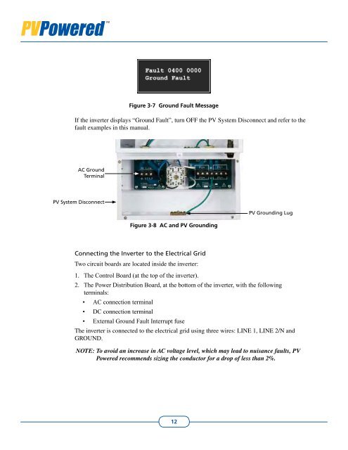
Figure 3-7 Ground Fault Message<br />
If the inverter displays “Ground Fault”, turn OFF the <strong>PV</strong> System Disconnect and refer to the<br />
fault examples in this manual.<br />
AC Ground<br />
Terminal<br />
<strong>PV</strong> System Disconnect<br />
Figure 3-8 AC and <strong>PV</strong> Grounding<br />
<strong>PV</strong> Grounding Lug<br />
Connecting the Inverter to the Electrical Grid<br />
Two circuit boards are located inside the inverter:<br />
1. The Control Board (at the top of the inverter).<br />
2. The Power Distribution Board, at the bottom of the inverter, with the following<br />
terminals:<br />
• AC connection terminal<br />
• DC connection terminal<br />
• External Ground Fault Interrupt fuse<br />
The inverter is connected to the electrical grid using three wires: LINE 1, LINE 2/N and<br />
GROUND.<br />
NOTE: To avoid an increase in AC voltage level, which may lead to nuisance faults, <strong>PV</strong><br />
<strong>Powered</strong> recommends sizing the conductor for a drop of less than 2%.<br />
12