Operations Manual - PV Powered
Operations Manual - PV Powered
Operations Manual - PV Powered

You also want an ePaper? Increase the reach of your titles
YUMPU automatically turns print PDFs into web optimized ePapers that Google loves.
Grid-tied Residential Inverters<br />
Installation and Operation <strong>Manual</strong><br />
!<br />
WARNING<br />
Negative grounded array: On a negatively grounded <strong>PV</strong> array, break only the<br />
positive conductor(s) in the <strong>PV</strong> System Disconnect. Do NOT break the<br />
negative conductor(s).<br />
Positive grounded array: On a positively grounded <strong>PV</strong> array, break only<br />
the negative conductor(s) in the <strong>PV</strong> System Disconnect. Do NOT break the<br />
positive conductor(s).<br />
5. Connect the <strong>PV</strong> equipment ground conductor to the ground lug located on the front<br />
inside portion of the <strong>PV</strong> System Disconnect. Refer to Figure 3-8.<br />
6. Verify all connections are properly torqued to 1.5 Nm or 4 in-lbs.<br />
7. Remove the 1A fuse from the external port by unscrewing the cap housing the fuse.<br />
Refer to Figure 3-5.<br />
!<br />
WARNING<br />
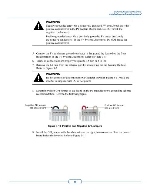
Do not connect or disconnect the GFI jumper shown in Figure 3-11 while the<br />
inverter is supplied with DC or AC power.<br />
8.<br />
Determine which GFI jumper to use based on the <strong>PV</strong> manufacturer’s grounding scheme<br />
recommendation. Refer to the following figure.<br />
Negative GFI jumper<br />
has a black wire<br />
Positive GFI jumper<br />
has a red wire<br />
Figure 3-10 Positive and Negative GFI Jumpers<br />
9.<br />
Install the GFI jumper with the white wire on the right, into connector J3 on the power<br />
board inside the inverter. Refer to Figure 3-11.<br />
15