Operations Manual - PV Powered
Operations Manual - PV Powered
Operations Manual - PV Powered

You also want an ePaper? Increase the reach of your titles
YUMPU automatically turns print PDFs into web optimized ePapers that Google loves.
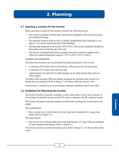
2. Planning<br />
2.1<br />
2.2<br />
Selecting a Location for the Inverter<br />
When choosing a location for the inverter, consider the following criteria:<br />
• The inverter is suitable for both indoor and outdoor installation; the inverter enclosure<br />
has a NEMA 3R rating.<br />
• The optimum location of the inverter is outside, shielded from direct exposure to sunlight<br />
(i.e. not on the south facing side of the building).<br />
• The heat sink temperature can exceed 158°F (70°C). The inverter should be installed so<br />
that people can not touch the top of the unit.<br />
• The inverter is designed and tested to produce maximum continuous output power<br />
within the ambient temperature range of -15°F to 105°F (-25°C to 40°C).<br />
Location and Clearances<br />
The following clearances are recommended for proper placement of the inverter:<br />
• A minimum of 36 inches between the bottom of the inverter box and the ground.<br />
• A minimum of 12 inches above the heat sink.<br />
• Approximately one half inch of width clearance on the right and left sides of the inverter<br />
cabinet.<br />
Visibility of the operating LEDs and display located at the top front of the inverter box<br />
should also be considered. Refer to Figure 2-1 for these within the inverter’s box.<br />
If the inverter is installed in an enclosed space, adequate ventilation must be provided.<br />
Guidelines for Mounting the Inverter<br />
The inverter should be mounted vertically to a flat, solid surface such as strut, concrete, or<br />
wood siding. It should be located near the <strong>PV</strong> arrays to minimize the DC conductor length.<br />
The bracket and paper mounting template provided make mounting the inverter quick and<br />
simple.<br />
The small bracket:<br />
• Has a vertical row of screw holes down the center and is designed for a single-stud<br />
mount. Refer to Figure 3-2.<br />
The large bracket:<br />
• Has two top screw holes at either end of the large bracket, 16” apart which are designed<br />
to match standard stud spacing. Refer to Figure 3-1.<br />
The inverter also has an internal mounting screw. Refer to Figure 2-1 for the location of this<br />
screw.<br />
PLANNING<br />
3