PT-8320 User Manual - Temperature Controls
PT-8320 User Manual - Temperature Controls
PT-8320 User Manual - Temperature Controls

You also want an ePaper? Increase the reach of your titles
YUMPU automatically turns print PDFs into web optimized ePapers that Google loves.
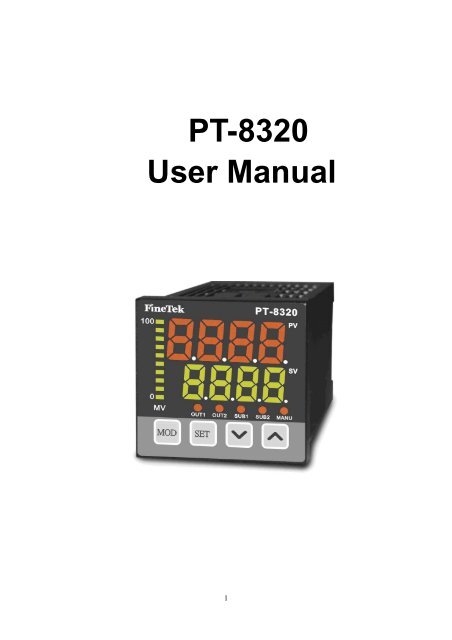
<strong>PT</strong>-<strong>8320</strong><br />
<strong>User</strong> <strong>Manual</strong><br />
1
DIMENSION / PANEL CUTOUT<br />
2
PANEL DESCRI<strong>PT</strong>ION:<br />
EXPLANATION FOR TERMINAL WIRING:<br />
3
STANDARD SPECIFICATIONS<br />
Power Supply<br />
85~265V AC 50/60 Hz<br />
Power Consumption<br />
7VA Maximum<br />
Upper:Red 4 digit of 7 segment display<br />
Display<br />
Bottom:Green 4 digit of 7 segment display<br />
10 segment bar-graph display<br />
Thermocouple:J, K, B, N, R, S, T, E<br />
Input Signal<br />
RTD:<strong>PT</strong>100, J<strong>PT</strong>100<br />
Direct Voltage:0~230mV<br />
Relay<br />
Output SPST-NO,5A/250V AC<br />
Control<br />
Pulse Output(Drive SSR)<br />
12VDC(NPN),20mA (MAX.)<br />
Output<br />
Analog<br />
4~20mA ,0~10V DC (MAX.600Ω)<br />
Alarm Output<br />
SPST-NO,5A/250V AC<br />
Alarm Delay Time<br />
0 ~ 99 second<br />
Alarm Output Hysteresis Adjustment<br />
0 ~ 9999 degree C<br />
Communication Interface<br />
RS485(MODBUS)<br />
Working <strong>Temperature</strong><br />
0 ~ 50℃ (20~85% RH)<br />
Cycle Time of Output Control<br />
0 ~ 50.0 seconds<br />
Digital<br />
0 ~ 3 digital<br />
Digital Filter<br />
1 ~ 100 times<br />
Control Method<br />
ON/OFF or PID+Fuzzy(Auto Tuning)<br />
Input Compensation -1999 ~ 9999<br />
Fraction Value 0.0 ~ 999.9<br />
Setting Range -1999 ~ 9999<br />
Accuracy<br />
0.3%FS ± 1digit<br />
Sampling Interval<br />
400ms<br />
Memory Retention<br />
EEPROM<br />
OTHER FUNCTIONS<br />
Sensor Error Detection<br />
Error code displayed on PV, with sensor error alarm<br />
output ability.<br />
HBA(Heater Break Alarm), Current error of heater can<br />
Detect the loop break and Heater Break Alarm<br />
be detected via CT transformer.<br />
Or using LBA(Loop Break Alarm) to detect system failure<br />
via software.<br />
Remote Set Point (RSP)<br />
Remote Setting Voltage、Current signal in order to<br />
change SV value<br />
EVENT function<br />
Remote control for executing specific command<br />
Re-transmission<br />
Re-transmit the voltage、current after the exchange of<br />
PV、SV<br />
4
A. ANUE DESCRI<strong>PT</strong>ION<br />
Main parameters selection<br />
Main Parameters Name of Parameter Description of Parameter<br />
PV value<br />
SV value<br />
Present value<br />
Setting value<br />
LV-0 Status information<br />
LV-1 PID setting<br />
LV-2 Advance setting for control<br />
Prog Ramp & Soak setting<br />
ALM Alarm setting<br />
StUP Hardware construction setting<br />
EXPA Expansion function setting<br />
CoMM Communication setting<br />
LoCK Lock function<br />
SCAL Analog auxiliary input setting<br />
rSP Remote Set Point auxiliary input setting<br />
Ct Current transformer input setting<br />
Under operating mode, please press MOD button in order to exchange above<br />
Main menu selection<br />
5
B. Parameters block description<br />
Parameters Display Name of Parameters Description of Parameters Display Range Default<br />
Pattern Display the present executing ~ 0<br />
pattern<br />
<br />
Step<br />
Display the present executing ~/ 0<br />
step<br />
<br />
Link Display the present link ~ 0<br />
setting<br />
<br />
Program Ramp & Soak control On/Off // rSt<br />
<br />
Advance Skip to next step / OFF<br />
<br />
Standby time<br />
Display waiting time for start ~ 0<br />
(minute)<br />
<br />
Elapse time<br />
Display schedule of executing ~ 0<br />
time (minute)<br />
Repeat time Display style executed time ~ 0<br />
Heater MV Display heater output .~. 0<br />
Cooler MV Display cooler output .~. 0<br />
section shows controller status, mainly for Ramp/Soak information.<br />
To go to LV-0, please press MOD once under SV/PV, the details are listed as below:<br />
‣ : Indication of the on-going pattern<br />
0:Not in the Ramp/Soak control mode, which means oPEr = onoF or Pid<br />
‣ : Indication of the on-going step<br />
0:Ramp/Soak control not starts yet.<br />
SV:Maintain the last SV (EXPA->Pend=SV) after patterns are completed.<br />
1、3、5、7、 9、11、13、15 :Ramp step<br />
2、4、6、8、10、12、14、16:Soak step<br />
‣ : Next pattern。(0: there is no next pattern)<br />
‣ : Program control: Change is effective while LV2->oPEr not be onoF or Pid.<br />
rSt:Reset ramp/soak status, and control/alarm output stop action.<br />
rUn:Ramp/soak control begins or continues.<br />
Hold:Hold ramp/soak timing<br />
‣ :Skip to next step.<br />
Ramp=>Soak:SV becomes the setting of the next soak step.<br />
Soak=>Ramp:<br />
EXPA=>PVSt=PV, PV reaches soak value after ramp time from the current PV.<br />
EXPA=>PVSt=SV, PV reaches soak value after ramp time from the current SV setting.<br />
‣ :Remaining time before controller actuates (min).<br />
‣ :Time performed of the on-going step (min)<br />
‣ :Remaining repeat times.<br />
‣ :Percentage of manipulate value for the heater.<br />
‣ :Percentage of manipulate value for the cooler.<br />
6
C. Parameters block description<br />
Parameters display Name of Parameters Description of Parameters Display range Default<br />
Tun Auto Tuning / OFF<br />
Proportional Proportional parameter ~. 2.0<br />
Integral Time Integral parameter (second) ~ 100<br />
Derivative Derivative parameter ~ 10<br />
Tau Fuzzy parameter . ~. 0.060<br />
Cooling Coefficient Cooling parameter . ~. 1.00<br />
MARE <strong>Manual</strong> reset . ~. 0<br />
Auto Tune Offset SV Offset during Auto-tuning ~ 0<br />
Heater Hysteresis Control output hysteresis for ~ 0<br />
heater<br />
Cooler Hysteresis Control output hysteresis for ~ 0<br />
cooler<br />
Heater period Cycle time of control heater .~. 5.0<br />
output (second)<br />
Cooler period Cycle time of control cooler .~. 5.0<br />
output (second)<br />
Dead band Dead band control / OFF<br />
Heater dead band Dead band of heater ~ 0<br />
Cooler dead band Dead band of cooler ~ 0<br />
CT current monitor Display CT -1.<br />
Heater burnout Heater break setting ~. 0<br />
section of parameters are used for basic control, P、I、D、tAU、CoEF parameters affect PID+Fuzzy control<br />
algorithm performance,theses parameter can be auto calculated by auto-tune function, without the need of complex<br />
PID tuning. Fuzzy compensation control makes system response faster and more reliable.<br />
To go to LV-1, press MOD twice under SV/PV, and its sub options are listed below:<br />
‣ : Auto tuning on:Auto tuning on oFF:Auto tuning off.<br />
When auto tuning is on, controller will start heating and cooling around the setting SV. After two cycles, PID<br />
parameters can be calculated. With these PID parameters, the controller can stabilize the system to a desire<br />
process value. You can also adopt the oFSt function (especially used during the auto tuning process), to prevent<br />
system over-heat during the auto tuning process.<br />
7
‣ :Proportional Gain parameter。Can be calculated by auto tuning or adjusted manually. This<br />
parameter is responsible to the system deviation. When offset occurs, proportional regulator<br />
responds to reduce the offset.<br />
‣ :Integral parameter。Can be calculated by auto tuning or adjusted manually. When steady offset<br />
exist in a consistent temperature, Integral regulator will start compensating until offset is fixed.<br />
‣ :Derivative parameter。Can be calculated by auto tuning or adjusted manually. Derivative regulator<br />
can predict the system trend by rate of change; derivative regulator will fix the offset in advance,<br />
before offset happens.<br />
‣ :Fuzzy factor parameter. Can be calculated by auto tuning or adjusted manually.<br />
Fuzzy control compensates the insufficiency of PID controller and helps to reach the target based<br />
on the deviation and rate of change.<br />
Bigger Tau, more Fuzzy compensation!<br />
‣ :Cooling coefficient. Can be calculated by auto tuning or adjusted manually.<br />
Cooler proportional gain = P / Coef<br />
This function is used in cooling control, to tell the performance of cooler.<br />
‣ :<strong>Manual</strong> reset.<br />
When Integral i=0, and PV>SV, then MV=MArE.<br />
‣ :SV offset setting during Auto tuning<br />
When this function is set up, auto tuning will make the system to oscillate around SV + oFSt . For<br />
example, SV=200°C;OFST= -10°C. Auto tuning will calculate as SV+OFST=200+(-10)=190°C,<br />
to avoid over-heating.<br />
‣ :Hysteresis for heater on/off control.<br />
‣ :Hysteresis for cooler on/off control.<br />
During ON/OFF control, control output should be turned off when PV>SV, and turned on when<br />
PVSV+HYS to turn off the control output, and turned on when PV
‣ :Enable/disable dead band control.<br />
‣ :Dead band for heater.<br />
‣ :Dead band for cooler.<br />
Heating and cooling range can be controlled via dead band setting<br />
Heater dead band control:If PV>SV+DB-H, heater is not active.<br />
Cooler dead band control:If PV0;DB-C>0<br />
Over SV+DB-H deactivates heater<br />
Under SV+DB-C deactivates cooler<br />
DB-H>0;DB-C
D. Parameters block description<br />
Parameter display Name of Parameters Description of Parameters Display Range Default<br />
Input Input signal selection //////<br />
////<br />
K type<br />
Operation Control mode selection //<br />
/<br />
OnoF<br />
Remote/Local SV Remote/unit intput / off<br />
Set Value <strong>Temperature</strong> setting ~ 0.0<br />
Dot Decimal point setting ~ dot1<br />
Unit <strong>Temperature</strong> unit display / ℃<br />
Multiplier PV Multiplier .~. 1.000<br />
Bias PV compensation input ~ 0.0<br />
Mode Control mode setting / H-C<br />
Filter Digital filter ~ 5<br />
Standby timer Waiting time for control<br />
starting (second)<br />
~ 0<br />
LbA detection Time Detection time of heater<br />
break (second)<br />
~ 0<br />
LbA detection Width Detection of temperature<br />
differentiation of heater<br />
~ 1.0<br />
break<br />
LED Status Bar Bar-graph display HEAT/CooL/Prog HEAT<br />
Transfer SV Hi Re-transmit SV high value ~ 100.0<br />
Transfer SV Lo Re-transmit SV low value ~ 0<br />
section is for advanced control parameters, ON/OFF or PID control mode can be configured to achieve the<br />
requirement.<br />
Under SV/PV mode press 3 times of MOD button, it is for main menu of LV-2, the sub-selection as following:<br />
‣ : Input signal<br />
• :K Type thermocouple input<br />
Input range:-200~1370°C 0.3%±1Digit。<br />
• :J Type thermocouple input<br />
Input range:-210~1200°C 0.3%±1Digit。<br />
• :T Type thermocouple input<br />
Input range:-200~400°C ±2°C±1Digit。<br />
• :E Type thermocouple input<br />
Input range:-200~1000°C 0.3%±1Digit。<br />
• :R Type thermocouple input<br />
Input range:-50~1760°C 0.3%±1Digit。<br />
• :S Type thermocouple input<br />
Input range:-50~1760°C 0.3%±1Digit。<br />
• :B Type thermocouple input<br />
Input range:250~1820°C ±8°C±1Digit。<br />
• :N Type thermocouple input<br />
Input range:-200~1300°C 0.3%±1Digit。<br />
• :<strong>PT</strong> Type thermocouple input<br />
Input range:-200~850°C 0.3%±1Digit。<br />
• :J<strong>PT</strong> Type thermocouple input<br />
Input range:-200~850°C 0.3%±1Digit。<br />
• :DC Type voltage input<br />
Input range:0~230mV 0.3%±1Digit。<br />
‣ : :ON-OFF; :PID<br />
:Program; :Program-ONOFF<br />
10
On/Off mode<br />
On/Off mode control is a very common and simple control mode. When the control output is programmed as<br />
the heating output and the temperature lower than setting value, control output start to activate; if the<br />
temperature is higher than setting value, control output deactivate in order to control the temperature. It also<br />
can adjust hysteresis band to reduce the overshooting on the system to achieve the best control and stability.<br />
PID mode<br />
MV<br />
SV<br />
PV<br />
PID control is corresponding to three constants which are proportional, integral, derivative. P is to handle the<br />
immediate error, I is to learn from the past and D is to handle the future. When control output is the heating<br />
output, the <strong>PT</strong>-series will apply PID+ Fuzzy algorithm to calculate a MV value (manipulate value) to be used in<br />
determining whether the control output should be strong or weak in order to constantly calculating the<br />
deviation of stability and prediction. The built-in Fuzzy control is to enhance the system in stability for<br />
achieving the best control and efficient.<br />
Program /Program ONOFF Mode<br />
Program mode offers 8 patterns temperature control. Every pattern includes temperature setup, time of ramp,<br />
time of soak. Measurement unit is minute. The 8 patterns temperature control allows the system to reach the set<br />
temperature within the set time of ramp(increase/decrease), and to maintain the set temperature within the set time<br />
of soak. It can also utilize Wait Width(EXPA->WAit) to let the system stay close to the setup even if the system is<br />
unable to follow the setup perfectly. There are 8 sub-patterns for set up in one pattern. Via Link function, 64<br />
sub-patterns temperature control can be given with ON/OFF and PID control as optional.<br />
11
‣ :Remote(RSP) or local SV<br />
:Remote mode (RSP); :Local mode。<br />
‣ :<strong>Temperature</strong> set value; Set value between。<br />
‣ :Decimal point set value。<br />
:decimal point 0<br />
:decimal point 1<br />
:decimal point 2<br />
:decimal point 3<br />
‣ :Measurement Unit setup。 ℃℉ /<br />
‣ :PV magnification adjustment。<br />
‣ :PV Offset input。When PV’s current value and expected value does not match, PV offset input<br />
function can be utilized for adjustment.PV = PV*MUL + biAS<br />
‣ :Control setup。<br />
:for system heating and cooling。<br />
:for system cooling。<br />
‣ :Digital filter;Decrease static signal。1~100 filter time can be set。 Digital filter can only affect PV<br />
value time update, not speed update。<br />
‣ :Wait Width:System can be set to control when the system can be actuated.When Wait Width is set<br />
to be 0, there will be no Wait function.<br />
‣ :LBA heater burnout time:Set LBA burnout cycle time(second)<br />
,when LbAt is set to be 0,there is no LBA function。<br />
‣ :LBA heater burnout temperature difference:Set LBA burnout temperature difference. When<br />
system is being heated and temperature increase is less than the temperature difference within<br />
LBA time, controller will assume heater is broken then LBA alarm signal will be sent out.<br />
‣ :Bargraphic Indicator<br />
:Heating control value,one light represents 10% value.<br />
:Cooling control value,one light represents 10% value.<br />
:8 modes are active.<br />
First light blinks:First mode of temperature increasing/decreasing is active.<br />
First light on constantly:First mode of temperature holding is active.<br />
Second light blinks:Second mode of temperature increasing/decreasing is active.<br />
Second light on constantly:Second mode of temperature holding is active.<br />
‣ :Set to re-transfer greatest SV value:<br />
‣ :Set to re-transfer smallest SV value:<br />
When output is the SV re-transfer analog output, SV can be transferred into the corresponding<br />
voltage and current output.<br />
Example:TR-H =100.0 TR-L=0.0 Liner output 0~10VDC<br />
SV 0.0 ~ 100.0 corresponds to 0~10V analog output<br />
12
E. Parameter Table<br />
Parameters display Name of Parameters Description of Parameters Display range Value<br />
Pattern NO. Pattern selection ~ 1<br />
Number of steps Steps needed to be performed ~ 8<br />
~ Set Value <strong>Temperature</strong> setup ~ 0<br />
~ Ramp time Time increase/decrease(min) ~ 0<br />
~ Soak time Time of temperature holding(min) ~ 0<br />
Repeat time Repeat time ~ 0<br />
Link pattern Link pattern ~8 0<br />
Time signal step Output signal step 1 ~ r1<br />
Signal 1 ON time Signal 1 ON time (min) ~ 0<br />
Signal 1 OFF time Signal 1 OFF time (min) ~ 0<br />
Time signal2 step Output signal step 2 ~ r1<br />
Signal2 ON time Signal 2 ON time (min) ~ 0<br />
Signal2 OFF time Signal 2 OFF time (min) ~ 0<br />
Parameter is a multi-pattern control function. Every pattern can perform 8 steps of temperature control.<br />
Via link pattern, 64 steps of temperature control can be performed.<br />
Press MOD 4 times under SV/PV mode,sub-menu can be selected under the main menu as below:<br />
‣ :8 pattern selection:Total of 8 patterns for selection. It is also the first action pattern among<br />
the 8 patterns.<br />
‣ :Step selection:Step 1~8. <strong>Temperature</strong> increase/decrease, temperature hold can be set in each<br />
step.<br />
‣ ~:<strong>Temperature</strong> setup:Set target temperature in each step.<br />
Ex.: SV=50 PV=30 SV1=50 tr1=1 ts1=2<br />
PV starts to increase to reach SV(increase speed is in inverse ratio to ramp time). After 1<br />
minute, SV reaches 50 and temperature begins holding for 2 minutes.<br />
‣ ~:Time of increase/decrease(Ramp):Set time needed(minute) in order to reach the set<br />
temperature.<br />
‣ ~:Time of holding(Soak):Time of hold(minute) after ramp time.<br />
13
‣ :Repeat time:Repeat time for each step<br />
Default setting=0,Repeat time= 0,Total action= 1<br />
Default setting=1,Repeat time= 1,Total action= 2, and so on.<br />
‣ :Pattern Link:Pattern selection followed by completion of each pattern.<br />
Ex.:Set Link=2 followed by Pattern 1.<br />
Link=1 followed by Pattern 2.<br />
‣ /:Signal output procedure:signal output setup<br />
r1:<strong>Temperature</strong> increase 1<br />
s1:<strong>Temperature</strong> holding 1<br />
r2:<strong>Temperature</strong> increase 2<br />
s2:<strong>Temperature</strong> holding 2<br />
‣ / :Signal on wait time:Signal output turns on at set wait time<br />
‣ /:Signal off wait time: Signal output turns off at set wait time.<br />
Signal will be turned off followed by time signal 1~2. Signal will be turned on in specified step.<br />
14
F. Parameter Table<br />
Parameters display Name of Parameters Description of Parameters Display range Reset Value<br />
Soft Start Alarm soft start / OFF<br />
Position 1 Alarm position 1 ~ 0.0<br />
Hysteresis 1 Hysteresis 1 ~ 0.0<br />
Delay Time 1 Delay time 1(sec) ~ 0<br />
Style 1 Style 1 ~ Sty1<br />
,<br />
Position 2 Alarm position 2 ~ 0.0<br />
Hysteresis 2 Hysteresis 2(sec) ~ 0.0<br />
Delay Time 2 Delay Time 2 ~ 0<br />
Style 2 Style 2 ~ Sty1<br />
,<br />
Position 3 Alarm position 3 ~ 0.0<br />
Hysteresis 3 Hysteresis 3(sec) ~ 0.0<br />
Delay Time 3 Delay Time 3 ~ 0<br />
Style 3 Style 3 ~ Sty1<br />
,<br />
Position 4 Alarm position 4 ~ 0.0<br />
Hysteresis 4 Hysteresis 4(sec) ~ 0.0<br />
Delay Time 4 Delay Time 4 ~ 0<br />
Style 4 Style 4 ~<br />
,<br />
Sty1<br />
There are 4 sets of alarm parameter setting designed to fit different application condition. In addition, there is<br />
Error Alarm function(ALM->StyLE->SErr) for additional protection for your system. Press MOD 5 times under SV/PV<br />
mode to go to ALM main menu. Sub-menu:<br />
‣ :Alarm soft start on/off<br />
Alarm will go off when system is within the alarm range twice.<br />
‣ :Position 1 setup.<br />
‣ :Hysteresis 1 setup.<br />
‣ :Delay time 1 setup(sec).<br />
‣ :Style 1 selection(Please refer to StyL alarm style description).<br />
‣ :Position 2 setup.<br />
‣ :Hysteresis 2 setup.<br />
‣ :Delay time 2 setup(sec).<br />
‣ :Style 2 selection(Please refer to StyL alarm style description).<br />
15
‣ :Position 3 setup.<br />
‣ :Hysteresis 3 setup.<br />
‣ :Delay time 3 setup(sec).<br />
‣ :Style 3 selection(Please refer to StyL alarm style description).<br />
‣ :Position 4 setup.<br />
‣ :Hysteresis 4 setup.<br />
‣ :Delay time 4 setup(sec).<br />
‣ :Style 4 selection(Please refer to StyL alarm style description).<br />
16
6.1 Offset High Alarm Alarm Style<br />
Alarm output on<br />
When PV>=SV+POS1, DY1 starts timing.<br />
When DY1 finishes timing, alarm sends out<br />
signal output.<br />
Alarm output off<br />
When PV=70, DY1 starts timing.<br />
When DY1 finishes timing, alarm<br />
sends out signal output.<br />
When PV
6.2 Offset High Alarm<br />
Alarm output on<br />
When PV>=SV-POS1, DY1 starts timing.<br />
When DY1 finishes timing, alarm sends out<br />
signal output.<br />
Alarm output off<br />
When PV=50, DY1 starts timing.<br />
When DY1 finishes timing, alarm<br />
sends out signal output.<br />
When PV
6.3 Offset Low Alarm<br />
Alarm output on<br />
When PV=SV-POS1+HYS1, alarm output stops.<br />
Ex.:<br />
PV= present value<br />
SV= set value<br />
POS1= Alarm set point<br />
DY1= Alarm delay time<br />
SV=60; POS1=10;<br />
HYS1=5; DY1=5;<br />
When PV=55, alarm output stops.<br />
19
6.4 Offset Low Alarm<br />
Alarm output on<br />
When PV=SV+POS1+HYS1, alarm output stops.<br />
Ex.:<br />
PV= present value<br />
SV= set value<br />
POS1= Alarm set point<br />
DY1= Alarm delay time<br />
SV=60; POS1=10;<br />
HYS1=5; DY1=5;<br />
When PV=75, alarm output stops.<br />
20
6.5 Out-Range Alarm<br />
Alarm output on<br />
When PV
6.6 In-Range Alarm<br />
Alarm output on<br />
When PV>=SV-POS1 and PV=50 and PV
6.7 Absolute Value High Alarm<br />
Alarm output on<br />
When PV>=POS1, DY1<br />
starts timing.<br />
When DY1 finishes timing, alarm sends out<br />
signal output.<br />
Alarm output off<br />
When PV=60, DY1 starts timing.<br />
When DY1 finishes timing, alarm<br />
sends out signal output.<br />
When PV
6.8 Absolute Value Low Alarm<br />
Alarm output on<br />
When PV=POS1+HYS1, alarm output stops.<br />
Ex.:<br />
PV= present value<br />
SV= set value<br />
POS1= Alarm set point<br />
DY1= Alarm delay time<br />
SV=60; POS1=10;<br />
HYS1=5; DY1=5;<br />
When PV=15, alarm output stops.<br />
6.9 SErr Signal Error Alarm<br />
Under this alarm mode, alarm will go off when PV encounters irregular condition.<br />
When PV indicates [––––] – Sensor break<br />
[U U U U] – Exceed low limit measuring range<br />
[o o o o] – Alarm goes off if exceeding high limit measuring range<br />
24
G. Parameter Table<br />
Parameters display Name of Parameters Description of Parameters Display range Reset Value<br />
Out1 ,,, Heat<br />
Out2 ~,, Cool<br />
control/alarm/output<br />
Sub1 ,,, ALM1<br />
transmission<br />
<br />
Sub2<br />
,,, ALM2<br />
<br />
<br />
AUX1<br />
<br />
<br />
AUX2<br />
AUX3<br />
AUX input<br />
,,,<br />
~<br />
None<br />
<br />
AUX4<br />
Event 1<br />
Event 2<br />
Event 3<br />
Event input<br />
,,,<br />
,,<br />
None<br />
Event 4<br />
Direction 1<br />
Direction 2<br />
Direction 3<br />
Input direction<br />
(forward or reverse)<br />
/<br />
Hi<br />
Direction 4<br />
<strong>User</strong>s can set parameters according to application environment and habit.<br />
‣ : Out 1 control/alarm/output transmission:Selectable output types<br />
‣ : Out 2 control/alarm/output transmission:Selectable output types<br />
‣ : Sub 1 control/alarm/output transmission:Selectable output types<br />
‣ : Sub 2 control/alarm/output transmission:Selectable output types<br />
:Heater control output<br />
:Cooler control output<br />
~:Alarm output to be performed with ALM for detail setup.<br />
:Heater break alarm to be performed with CT transformer.<br />
:Loop break alarm to detect heater break by software. This function has to be performed<br />
with LV-2→LbAt and LbAW.<br />
:Controller has to work with analog output to transfer PV value to voltage/current value.<br />
For module 0-10vDC、4-20mA, please refer to SCALE.<br />
:Controller has to work with analog output to transfer SV value to voltage/current value.<br />
For module 0-10vDC、4-20mA, please refer to LV-2→tr-H and tr-L.<br />
~:In specified steps, ts1~2 will send out signal after On Wait Time and ts1~2<br />
will be turned off after Off Wait Time.<br />
25
Ex.: ts1=S2, on=2, off=3<br />
After 2 minutes in <strong>Temperature</strong> Holding Step 2, ts1 will be on. After another<br />
1 minute, it will be off again.<br />
After ts-1~2 goes to the next step, all signal will be off until it reaches specified steps.<br />
:When 8 steps are completed, Pend will receive a pulse signal.<br />
:When performing 8 steps, Stg will receive pulse signal when it is in ramp or soak<br />
Ex.:To correspond SV 0.0~100.0 to 0-10VDC output, please set LV-2→tr-H = 100,<br />
LV-2→tr-L = 0<br />
‣ :Aux 1 input<br />
‣ :Aux 2 input<br />
‣ :Aux 3 input<br />
‣ :Aux 4 input<br />
Offer different signal input including remote SV value(RSP)、remote Event, current transformer, and<br />
CT input.<br />
:Remote SV value setup with 0-10V,0-20mA module input.<br />
Please go to rSP in main menu for detail setup.<br />
:Current transformer input for current measurement with Ct module.<br />
Please go to Ct in main menu for detail setup.<br />
~:Specified Event can be set with Event module.<br />
‣ : Event 1 input<br />
‣ : Event 2 input<br />
‣ : Event 3 input<br />
‣ : Event 4 input<br />
~:Specified Event can be set with Event module.<br />
Under Stup→EVt1~4 in main menu,corresponding Event(Reset,Remote<br />
26
-Local ,<strong>Manual</strong>, Hold, Advance) can be set。Simply switch on to perform.<br />
:Switch on => LV-2->r-L=on<br />
Switch off => LV-2->r-L=oFF<br />
:Switch on => Switch between manual and standard mode<br />
<br />
:Switch on => LV-0->Prog=rSt<br />
Switch off => LV-0->Prog=rUn<br />
:Switch on => LV-0->Prog=HoLd<br />
Switch off=>LV-0->Prog=Retrieve Hold original setting<br />
:Switch on => LV-0->AdV=on<br />
‣ :Output direction 1(Forward/reverse)<br />
‣ :Output direction 2(Forward/reverse)<br />
‣ :Output direction 3(Forward/reverse)<br />
‣ :Output direction 4(Forward/reverse)<br />
Select Forward output or Reverse Output with Out1, Out2, Sub1, Sub2.<br />
27
H. Parameter Table<br />
Parameters display Name of Parameters Description of Parameters Display range Reset Value<br />
Set value upper limit SV upper limit setup , ~ 9999<br />
SV-H>SV-L<br />
Set value lower limit SV lower limit setup , ~ -1999<br />
SV-LoPEr=Prog or P-nF)<br />
‣ :Pend status:Set controller’s mode after 8 patterns finish running.<br />
It can be set as Reset. Controller will return to rSt after 8 patterns complete and alarm does not<br />
go off.(LV0->Prog=rSt)<br />
It can be set as SV. Controller will remain in the last SV after 8 patterns complete and continues<br />
functioning.<br />
‣ :Wait Width:When performing 8 patterns, ∣PV-SV∣has to be smaller than Wait width in order to<br />
enter the next step and follow the setting.<br />
Default value 0: Disable.<br />
28
‣ : Ramp/Soak initial SV setting, the SV initial value of the first step or when skip into ramp step, the SV<br />
initial value accumulate from the current PV or according to the SV setting.<br />
PV:Perform based on PV setup<br />
SV:Perform based on SV setup<br />
‣ :PV/SV main menu auto return:Display will automatically returned to PV/SV main menu when there<br />
is no new setup for time input. Setup range is oFF、10、20、30、40、50、60.(Default oFF Not return<br />
to PV/SV automatically,Unit:second)<br />
‣ :Alarm latch:HBA latch alarm can be set.<br />
When latch mode is on, HBA alarm not de-energize while system outside the alarm range.<br />
(default:OFF)<br />
‣ :Preset default value retrieval(reset):This mode can retrieve preset default value.<br />
29
I、 List of parameters<br />
Parameters display Name of Parameters Description of Parameters Display range Default<br />
ID Identification ~ 1<br />
BPS. Baud rate Describe below 9600<br />
Style Transmitting Style Describe below 8n1<br />
Format Transmitting Format Hex/Ascii Hex<br />
Time Out Setting for Time limit ~ 100<br />
Allow Write Allow writing for parameters / ON<br />
‣ :Identify the address of control unit<br />
‣ :Selection for Baud Rate communication<br />
600 :Baud rate 600<br />
1200 :Baud rate 1200<br />
2400 :Baud rate 2400<br />
4800 :Baud rate 4800<br />
9600 :Baud rate 9600<br />
19200:Baud rate 19200<br />
38400:Baud rate 38400<br />
‣ :Selection for communication style<br />
8n1:None parity check, Stops one bit<br />
8n2:None parity check, Stops two bits<br />
8o1:Odd check, Stops one bit<br />
8E1:Even check, Stops one bit<br />
‣ :Selection for communication format<br />
HEH.:Hex mode<br />
AS.Ci:ASCII mode<br />
‣ :Setting for time limit<br />
‣ : Allow writing, setting the communication with parameters writing(ON/OFF)<br />
30
J、 Parameters block description<br />
Parameter Display Name of Parameters Description of Parameters Setting Range Default<br />
LABEL Lock selection ~ LB00<br />
Through LAbe parameter setting, it is adjust the main menu selectable and good for<br />
use friendly, avoid the possibility mistake in setting function.<br />
LB00 LB01 LB02 LB03 LB04<br />
PV/SV ● ● ● ● ●<br />
LV-0 ● ● ●<br />
LV-1 ● ● ●<br />
LV-2 ● ● ●<br />
Prog ● ● ●<br />
ALM ● ● ●<br />
StUP<br />
●<br />
EXPA<br />
●<br />
CoMM<br />
●<br />
LoCK ● ● ● ● ●<br />
SCAL<br />
●<br />
rSP<br />
●<br />
Ct<br />
●<br />
CALI<br />
●<br />
MANU ● ● ● ● ●<br />
CALI:Calibration selection<br />
MANU:<strong>Manual</strong> selection<br />
31
K. Parameter Table<br />
Parameter Display Name of Parameters Description of Parameters Setting Range Pre-set<br />
value<br />
Scale Hi Greatest PV value ~ 100.0<br />
Scale Lo Lowest PV value ~ 0.0<br />
Sensor input voltage Sensor AD voltage<br />
Sensor Hi Greatest voltage input .~. 0.25<br />
Sensor Lo Lowest voltage input .~. 0.1<br />
Scale Enable Scale enable switch / OFF<br />
‣ :Greatest PV value:Set PV value in Span voltage.<br />
‣ :Lowest PV value:Set PV value in Zero voltage.<br />
PV can be re-transmitted for t-PV(Transfer PV).<br />
‣ :Sensor AD voltage:Set SCHi、SCLi.<br />
‣ :Greatest voltage input:Set greatest measuring voltage in Sensor input.<br />
‣ :Lowest voltage input:Set lowest measuring voltage in Sensor input.<br />
‣ :Input switch:ON/OFF voltage input in PV display<br />
Ex. 1:PV value 0.0~ 100.0 corresponds to 0~10V<br />
DC output in SUB2 terminal<br />
Steps:<br />
1、 StUP→SUB2 = t-PV in main menu<br />
2、 SCAL→SCH = 100.0 in main menu<br />
3、 SCAL→SCL = 0.0 in main menu<br />
4、 Complete setup<br />
Ex. 2:0-10mV value corresponds to PV 0.0~200.0 in<br />
Sensor output<br />
Steps:<br />
1、 Connect 0-10mV DC to <strong>PT</strong>8 in Sensor<br />
output terminal.<br />
2、 SCAL→SCH = 200.0<br />
3、 SCAL→SCL = 0.0<br />
4、 Input 0V to observe SCAL→SEnS and input<br />
value into SCAL→SCLi<br />
5、 Input 10mV to observe SCAL→SEnS and<br />
input value into SCAL→SCHi<br />
6、 SCAL→SCEN = ON<br />
7、 Back to main menu<br />
Input 0mV, PV = 0.0?<br />
Input 10mV, PV = 200.0?<br />
8、 Complete setup<br />
32
L. Parameter Table<br />
Parameter Display Name of Parameters Description of Parameters Setting Range Pre-set value<br />
Scale Hi Greatest SV Value(RSP) ~ 10.0<br />
Scale Lo Lowest SV Value(RSP) ~ 0.0<br />
AD Voltage AD Voltage<br />
Input Hi Set Span Voltage .~. 2.264<br />
input Lo Set Zero Voltage .~. 0.072<br />
Note:LV-2 → r-L has to be turned on in order to perform each mode.<br />
‣ :Greatest SV Value:Set greatest SV value in Span voltage.<br />
‣ SCL :Lowest SV Value:Set lowest SV value in Zero voltage.<br />
‣ :Sensor AD Voltage:To calibrate zero, span voltage<br />
‣ : Set Span Voltage:Set greatest voltage output for AD.<br />
‣ :Set Zero Voltage:Set lowest voltage value for AD.<br />
Ex.:Set input of 0~10vdc in AUX1<br />
SV value: 0.0~100.0<br />
Steps:<br />
1、 Connect 0-10VDC output to<br />
<strong>PT</strong>8(AUX1)(RSP 0-10Vdc)<br />
2、 Select rSP under StUP→AUX1 in main<br />
menu.<br />
3、 Select rSP→SCH = 100.0 in main menu<br />
4、 Select rSP→SCL = 0.0 in main menu<br />
5、 Input 0V to observe rSP→AD.Input<br />
value into rSP→SCLi<br />
6、 Input 10v to observe rSP→AD. Input<br />
value into rSP→SCHi<br />
7、 Select LV-2→r-L = ON in main menu<br />
8、 Back to PV/SV main menu<br />
Input 0v, SV = 0.0<br />
Input 10v,SV = 100.0<br />
9、 Complete setup<br />
33
M. Parameter Table<br />
Display Name Description Range Preset Value<br />
Scale Hi Scale Hi(CT current) ~ 35.0<br />
Scale Lo Scale Lo(CT current) ~ 0.0<br />
AD Voltage AD Voltage Indication<br />
Input Hi Set Span voltage .~. 2.5<br />
input Lo Set Zero voltage .~. 0.1<br />
Note:Tolerance of greatest CT current input is 30mA<br />
‣ :Scale Hi:Set greatest CT value in Span voltage<br />
‣ :Scale Lo:Set lowest CT value in Zero voltage<br />
‣ :Sensor AD Voltage:To calibrate zero, span voltage<br />
‣ :Set Span voltage:。<br />
‣ :Set Zero voltage:。<br />
Ex.:When hardware detects heater breakage, CT<br />
input utilizes AUX1 and SUB1 to send alarm signal.<br />
Steps:(Please refer to CT input module in the right)<br />
1、 Connect CT transformer to <strong>PT</strong>8(AUX1)。<br />
2、 Select Ct under StUP→AUX1 in main<br />
menu.<br />
3、 Select HbA under StUP→SUB1 in main<br />
menu.<br />
4、 Observe AD voltage exceeds 0.100v<br />
when heater is on under Ct→AD in main<br />
menu. If AD voltage exceeds 0.100v, it<br />
means transformer is connected correctly.<br />
5、 Observe Ct value(HNC) when heater is off<br />
and (HNO) when heater is on under<br />
LV-1→Ct in main menu.<br />
6、 Input proper set value (HNC < Hb < HNO)<br />
under LV-1→Hb in main menu. Normal<br />
setup is 70% of HNO.<br />
Ex.:Calibrate CT transformer:<br />
Transformer input is 5A;Ratio is 1000:1<br />
1、 Main menu Ct→SCH = 5.0<br />
2、 Main menu Ct→SCL = 0.0<br />
3、 Input 0A to observe<br />
Ct→AD display,input value into<br />
SCLi<br />
4、 Input 5A to observe AD,input<br />
value into SCHi<br />
5、 Complete setup.<br />
7、 Complete setup.<br />
34
N、 Parameter Table<br />
Display Name Description Range Preset Value<br />
Analog input calibrate Sensor input calibration<br />
Analog output1 calibrate Analog output1 calibration<br />
Analog output2 calibrate Analog output2 calibration<br />
Analog output3 calibrate Analog output3 calibration<br />
Analog output4 calibrate Analog output4 calibration<br />
Fuzzy Switch FuzzySwitch / ON<br />
TEMP121 information <strong>Temperature</strong> Information<br />
Calibration mode can be performed based on each input/output.<br />
To go to Cali main menu, please press<br />
and hold for 5 seconds under SV/PV mode.<br />
To go back to SV/PV mode, please press and hold<br />
for 5 seconds under Fine-Tek mode.<br />
‣ :Sensor Input Calibration:After calibration, voltage and resistance can be measured accurately.<br />
Sub-menu:<br />
1、PAS :Input correct password to enter.(password:12)<br />
2、0mV :Calibrate 0mv input.<br />
3、50mV:Calibrate 50mV input.<br />
4、r100:Calibrate 100Ω input.<br />
5、r300:Calibrate 300Ω input.<br />
6、Adjt: <strong>Temperature</strong> compensation calibration.<br />
PV = PV + Adjt<br />
(Please see Example 1 for detail)<br />
‣ ~:Analog Output Calibration: Calibration will be performed based on each analog output to<br />
get accurate Span & Zero voltage<br />
Sub-menu:<br />
1.AdjF:Calibrate Span voltage output(0~10v), current(4~20mA)<br />
2.Adj0:Calibrate Zero voltage input(0~10v), current(4~20mA)<br />
(Please see Example 2 for detail)<br />
‣ :Fuzzy Switch:Whether Fuzzy is to be activated when setting up PID.(Preset Value:ON)<br />
‣ :IC <strong>Temperature</strong> Indication:To indicate temperature information.<br />
IC temperature for thermocouple input.<br />
PV = TC temperature difference + internal IC temperature<br />
35
Example 1:Calibrate Sensor input<br />
Setup:<br />
10、 Connect calibrator with sensor input<br />
11、 Press and hold for 5 seconds to<br />
enter Cali mode<br />
12、 Select AiC<br />
13、 Press under Aic→PAS = 12<br />
14、 Set calibrator output= 0mV<br />
15、 Press to enter Aic→0mv to edit.<br />
Press until value is stable, then<br />
press to confirm.<br />
16、 Set calibrator output= 50mV<br />
17、 Press to enter Aic→50mv to<br />
edit. Press until value is stable,<br />
then press to confirm.<br />
18、 Set calibrator output= 100Ω<br />
19、 Press to enter Aic→r100 to edit.<br />
Press until value is stable, then<br />
press to confirm.<br />
Note:(Please follow RTD wiring steps<br />
when calibrating)<br />
20、 Set calibrator= 300Ω<br />
21、 Press to enter Aic→r300 to edit.<br />
Press until value is stable, then<br />
press to confirm.<br />
Note:(Please follow RTD wiring steps<br />
when calibrating)<br />
22、 Press to enter Aic→r300 to edit.<br />
Press to enter Aic→Adjt to edit<br />
error of room temperature and present<br />
temperature IC.<br />
Note:(Please refer present temperature<br />
IC in inFo→tEMP)<br />
23、 Setup complete.<br />
Example 2:Calibrate OUT1 analog output 0~10v<br />
DC<br />
Setup:<br />
1、 Connect calibrator with analog output<br />
2、 Press and hold for 5 seconds to<br />
enter Cali mode<br />
3、 Select AoC1<br />
4、 Press to enter AoC1→AdjF to<br />
edit. Observe calibrator voltage value,<br />
then press 、 to get 10.00v.<br />
5、 Press to enter AoC1→Adj0 to<br />
edit. Observe calibrator voltage value,<br />
then press 、 to get 0.00v.<br />
Press to confirm.<br />
6、 Setup complete.<br />
36
O、 Parameters block description<br />
Parameter Name of Parameters Description of Parameters Setting Range Default<br />
<strong>Manual</strong> operation Display PV value ~<br />
Heater MV Control heater output manipulate .~. 0<br />
value<br />
Cooler MV Control cooler output manipulate .~. 0<br />
value<br />
‣ :Display PV value<br />
‣ :Control heater output manipulate value<br />
‣ :Control cooler output manipulate value<br />
37