ECS-200 manual E4.pdf - Temperature Controls
ECS-200 manual E4.pdf - Temperature Controls
ECS-200 manual E4.pdf - Temperature Controls

You also want an ePaper? Increase the reach of your titles
YUMPU automatically turns print PDFs into web optimized ePapers that Google loves.
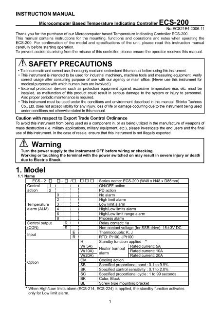
INSTRUCTION MANUAL<br />
Microcomputer Based <strong>Temperature</strong> Indicating Controller <strong>ECS</strong>-<strong>200</strong><br />
No.<strong>ECS</strong>21E4 <strong>200</strong>6.11<br />
Thank you for the purchase of our Microcomputer based <strong>Temperature</strong> Indicating Controller <strong>ECS</strong>-<strong>200</strong>.<br />
This <strong>manual</strong> contains instructions for the mounting, functions and operations and notes when operating the<br />
<strong>ECS</strong>-<strong>200</strong>. For confirmation of the model and specifications of the unit, please read this instruction <strong>manual</strong><br />
carefully before starting operation.<br />
To prevent accidents arising from the misuse of this controller, please ensure the operator receives this <strong>manual</strong>.<br />
SAFETY PRECAUTIONS<br />
• To ensure safe and correct use, thoroughly read and understand this <strong>manual</strong> before using this instrument.<br />
• This instrument is intended to be used for industrial machinery, machine tools and measuring equipment. Verify<br />
correct usage after consulting purpose of use with our agency or main office. (Never use this instrument for<br />
medical purposes with which human lives are involved.)<br />
• External protection devices such as protection equipment against excessive temperature rise, etc. must be<br />
installed, as malfunction of this product could result in serious damage to the system or injury to personnel.<br />
Also proper periodic maintenance is required.<br />
• This instrument must be used under the conditions and environment described in this <strong>manual</strong>. Shinko Technos<br />
Co., Ltd. does not accept liability for any injury, loss of life or damage occurring due to the instrument being used<br />
under conditions not otherwise stated in this <strong>manual</strong>.<br />
Caution with respect to Export Trade Control Ordinance<br />
To avoid this instrument from being used as a component in, or as being utilized in the manufacture of weapons of<br />
mass destruction (i.e. military applications, military equipment, etc.), please investigate the end users and the final<br />
use of this instrument. In the case of resale, ensure that this instrument is not illegally exported.<br />
Warning<br />
Turn the power supply to the instrument OFF before wiring or checking.<br />
Working or touching the terminal with the power switched on may result in severe injury or death<br />
due to Electric Shock.<br />
1. Model<br />
1.1 Name<br />
<strong>ECS</strong> - 2 - / , Series name: <strong>ECS</strong>-<strong>200</strong> (W48 x H48 x D85mm)<br />
Control 1 ON/OFF action<br />
action 2 PD action<br />
0 No alarm<br />
<strong>Temperature</strong><br />
alarm (ALM)<br />
2 High limit alarm<br />
3 Low limit alarm<br />
4 High/Low limits alarm<br />
6 High/Low limit range alarm<br />
8 Process alarm<br />
Control output R Relay contact: 1a<br />
(CON) S Non-contact voltage (for SSR drive): 15 3V DC<br />
E<br />
Thermocouple: K, J<br />
Input<br />
R<br />
RTD: Pt100, JPt100<br />
H Standby function applied *<br />
W( 5A) Rated current: 5A<br />
Option<br />
Heater burnout<br />
W(10A)<br />
Rated current: 10A<br />
alarm<br />
W(20A)<br />
Rated current: 20A<br />
CM Cooling action<br />
SB Specified proportional band : 0.1 to 9.9%<br />
SK Specified control sensitivity : 0.1 to 2.0%<br />
SC Specified proportional cycle : 1 to 99 seconds<br />
BK Color, Black<br />
BL Screw type mounting bracket<br />
* When High/Low limits alarm (<strong>ECS</strong>-214, <strong>ECS</strong>-224) is applied, the standby function activates<br />
only for Low limit alarm.<br />
1
1.2 How to read the model label<br />
Model label is attached to the case and inner assembly.<br />
(Model label)<br />
(Example)<br />
(1)<br />
(2)<br />
(3)<br />
E C S – 2 2 4 – R / E<br />
H<br />
S C ( 3 0 )<br />
N o .<br />
(1): Model<br />
(2): Option codes<br />
(3): Serial number (Indicated only on the internal assembly)<br />
For the Heater burnout alarm [HB], specified proportional band [SB], specified control sensitivity [SK]<br />
and specified proportional cycle [SC], the specified value is entered in the bracket ( ).<br />
2. Name and functions of the sections<br />
(1) (2)<br />
Relay contact output/Thermocouple input<br />
Standby function applied<br />
Specified proportional cycle (30sec)<br />
(3)<br />
(4)<br />
(7) (5)<br />
(8) (6)<br />
(9) (11)<br />
(10)<br />
(Fig. 2-1)<br />
(1) PV indicator<br />
When the digital display indicates the PV (process variable), the red LED is lit.<br />
(2) SV indicator<br />
When the digital display indicates the SV (Desired value), the green LED is lit.<br />
(3) Digital display<br />
Indicates the PV (process variable), SV (Desired value), setting characters with a red LED.<br />
(4) CON: Control output indicator<br />
When the control output is on, the green LED is lit.<br />
(5) ALM: <strong>Temperature</strong> alarm action indicator<br />
When the temperature alarm output is on, the red LED is lit.<br />
(6) HB: Heater burnout alarm, Sensor burnout alarm action indicator<br />
When the Heater burnout alarm or Sensor burnout alarm is on, the red LED is lit.<br />
(7) Increase key<br />
Increases the numeric value or selects the set value.<br />
(8) Decrease key<br />
Decreases the numeric value or selects the set value.<br />
(9) Sub mode key<br />
By pressing the Mode key while pressing the Sub mode key in the PV/SV display mode,<br />
the unit proceeds to the Auxiliary function setting mode.<br />
(10) Mode key<br />
Selects the setting mode, or registers the set value or selected value.<br />
(11) Reset key<br />
Performs the auto-reset (offset correction).<br />
How to switch the PV or SV indication<br />
Press the Increase key to indicate the PV, and the Decrease key to indicate the SV for approx.<br />
10 seconds respectively.<br />
How to register the set value<br />
Press the Mode key to register the set value (numeric value).<br />
When the key operation is stopped in the process of setting, the unit automatically reverts to the PV/SV<br />
display mode in approx. 30 seconds, and the value before the key operation was stopped is registered.<br />
2
3 Settings<br />
3.1 Operation flowchart<br />
Power ON<br />
Warm-up status (approx. 3sec)<br />
PV/SV display mode<br />
[Basic function setting mode]<br />
SV setting<br />
<strong>Temperature</strong> alarm setting<br />
Heater burnout alarm setting<br />
+<br />
[Auxiliary function setting mode]<br />
Set value lock selection<br />
Scaling high limit setting<br />
Scaling low limit setting<br />
Sensor correction setting<br />
• The setting item with dotted lines is optional, and it appears only when the option is added.<br />
• “<strong>Temperature</strong> alarm setting” is indicated only when the alarm function is added.<br />
After the power is switched on, the Digital display indicates [ ] for approx. 3 seconds during warm-up.<br />
During this time, all outputs and LED indicators are in OFF status.<br />
After that, control starts indicating the PV (process variable) or SV (desired value) on the Digital display.<br />
Caution<br />
During warm-up status (for approx. 3 seconds), do not operate any keys since the instrument<br />
specifications may be altered.<br />
Do not turn the power supply ON during key operations.<br />
3.2 PV/SV display mode<br />
Control status such as PV or SV is indicated on the Digital display.<br />
The PV indicator is lit while the PV is indicated on the Digital display, and the SV indicator is lit while<br />
the SV is indicated on the display.<br />
Default value: PV indication<br />
3.3 Basic function setting mode<br />
Characters SV setting<br />
• Sets the SV (Desired value).<br />
Alternating display<br />
• Setting range: SV low limit to SV high limit<br />
• Default value: 0<br />
<strong>Temperature</strong> alarm setting<br />
• Sets the action point of the temperature alarm.<br />
Alternating display • Not available for the <strong>ECS</strong>-2 0 type which has no temperature alarm.<br />
• Off when set to 0<br />
However, for the RTD input and the process alarm is selected,<br />
the alarm activates even if the set point is set to “0”.<br />
• Setting range: Refer to (Table 3.3-1) on page 4.<br />
• Default value: 0<br />
3
Alternating display<br />
Heater burnout alarm setting<br />
• Sets the heater current value.<br />
• Available only when the W option is applied.<br />
• The alarm output is maintained once the alarm activates.<br />
To release the alarm, turn the power supply to the unit OFF, then ON<br />
again.<br />
• Setting range: 0 to 100%<br />
• Default value: 0%<br />
Formula of the action point (set value)<br />
Hc<br />
Where Ap: Action point (set value) (%)<br />
Ap = x 100 Hc: Heater maximum current (A)<br />
Rv<br />
Rv: Rated value (5A, 10A, 20A)<br />
It is recommended that the action point should be set around 80% of<br />
the action point considering the voltage fluctuation.<br />
(Table 3.3-1)<br />
Alarm type<br />
Setting range<br />
High limit alarm -100 to100<br />
Low limit alarm -100 to 100<br />
High/low limits alarm (1 to 100)<br />
High/low limit range alarm (1 to 100)<br />
Process alarm<br />
Scaling low limit to scaling high limit<br />
3.4 Auxiliary function setting mode<br />
Characters Set value lock selection<br />
• Locks set values to prevent setting errors.<br />
• (Lock) : None of set values can be changed.<br />
(Unlock): All set values can be changed.<br />
Specified rated value Scaling high limit setting<br />
Alternating display<br />
• Sets the Scaling high limit value of the scale.<br />
(Scaling high limit value depends on the sensor type.)<br />
• Setting range: Refer to (Table 3.4-1).<br />
Specified rated value<br />
Alternating display<br />
Alternating display<br />
• Default value: Specified rated value<br />
Scaling low limit setting<br />
• Sets the Scaling low limit value of the scale.<br />
(Scaling low limit value depends on the sensor type.)<br />
• Setting range: Refer to (Table 3.4-1).<br />
• Default value: Specified rated value<br />
Sensor correction setting<br />
• Sets the sensor correcting value.<br />
• Setting range: -30 to 30<br />
• Default value: 0<br />
Sensor correction function<br />
This corrects the input value from the sensor. When a sensor cannot be set at the exact location where<br />
control is desired, the sensor measured temperature may deviate from the temperature in the controlled<br />
location.<br />
When controlling with plural controllers, sometimes the measured temperatures (input value) do not<br />
concur due to difference in sensor accuracy or dispersion of load capacities.<br />
In such a case, the control can be set at the desired temperature by adjusting the input value of sensors.<br />
4
(Table 3.4-1)<br />
Setting Minimum scale span<br />
Sensor type<br />
range accuracy guaranteed<br />
0 to 300<br />
0 to 400<br />
K<br />
0 to 600<br />
0 to 800<br />
0 to 999<br />
300<br />
0 to 300<br />
0 to 400<br />
J<br />
0 to 600<br />
0 to 800<br />
Pt100<br />
0 to <strong>200</strong><br />
<strong>200</strong><br />
JPt100 -100 to 300<br />
If the scale range is set narrower than the minimum scale span accuracy guaranteed, the accuracy<br />
is not guaranteed.<br />
4. Operation<br />
After the unit is mounted to the control panel and wiring is completed, operate the unit following the<br />
procedures below.<br />
(1) Turn the power supply to the <strong>ECS</strong>-<strong>200</strong> ON.<br />
After the power is switched on, the Digital display indicates [ ] for approx. 3 seconds during<br />
warm-up.<br />
During this time, all outputs and LED indicators are in OFF status.<br />
After that, control starts indicating the PV (process variable) or SV (desired value) on the Digital display.<br />
Caution<br />
During the warm-up status (for approx. 3 seconds), do not operate any keys since the instrument<br />
specifications may be altered.<br />
Do not turn the power supply ON during key operation.<br />
(2) Input the set value.<br />
Input each set value, referring to Chapter “3. Settings”.<br />
(3) Turn the load circuit power ON.<br />
Control action starts so as to keep the control target at the SV.<br />
5. Other functions<br />
(1) Operational error protection function<br />
If a key operation has not been performed for approx. 30 seconds during the Basic function setting mode<br />
or Auxiliary function setting mode, the controller automatically switches to the PV/SV display mode, and<br />
the set value is registered.<br />
(2) Sensor burnout alarm (Burnout, upscale)<br />
If the thermocouple is burnt out, the control output is turned OFF and the Sensor burnout alarm<br />
action indicator lights. At this time, if the PV is indicated on the Digital display, [ ] flashes.<br />
(Once the alarm activates, the output is held until the power to the instrument is switched OFF.)<br />
When the PV exceeds 999 of “K” input, 900 of “J” input, 350 of Pt100 input, the same action<br />
occurs as the above.<br />
(3) Self-diagnosis<br />
The CPU is monitored by a watchdog timer, and when an abnormal status is found on the CPU,<br />
the controller is switched to warm-up status.<br />
(4) Automatic cold junction temperature compensation (only for thermocouple input)<br />
This detects the temperature at the connecting terminals between the thermocouple and the instrument,<br />
and always maintains the same status as when the reference junction is located at 0 (32 ).<br />
5
6. Action explanations<br />
6.1 Proportional action<br />
Heating (reverse) action<br />
Cooling (direct) action (Option: CM)<br />
Proportional band<br />
Proportional band<br />
ON<br />
ON<br />
Control action<br />
OFF<br />
OFF<br />
SV setting<br />
SV setting<br />
Relay contact<br />
output<br />
Non-contact<br />
voltage output<br />
+<br />
6 6<br />
6<br />
6<br />
6<br />
6<br />
7 7<br />
7<br />
7<br />
7<br />
7<br />
Cycle action according to deviation Cycle action according to deviation<br />
6 + 6 + 6 + 6 + 6 + 6<br />
15V DC 15/0V DC 0V DC 0V DC 0/15V DC 15V DC<br />
7<br />
7<br />
7<br />
7<br />
7<br />
7<br />
Cycle action according to deviation Cycle action according to deviation<br />
Indicator (CON)<br />
Green<br />
Lit<br />
Unlit<br />
Unlit<br />
Lit<br />
: Acts ON or OFF.<br />
6.2 ON/OFF action<br />
Heating (reverse) action<br />
Hysteresis<br />
Cooling (direct) action [Option: CM]<br />
Hysteresis<br />
ON<br />
ON<br />
Control action<br />
OFF<br />
OFF<br />
SV setting<br />
SV setting<br />
Relay contact<br />
output<br />
6<br />
7<br />
6<br />
7<br />
6<br />
7<br />
6<br />
7<br />
Non-contact<br />
voltage output<br />
+<br />
6 +<br />
15V DC<br />
7<br />
6 +<br />
0V DC<br />
7<br />
6 +<br />
0V DC<br />
7<br />
6<br />
15V DC<br />
7<br />
Indicator (CON)<br />
Green<br />
Lit Unlit Unlit Lit<br />
: Control sensitivity<br />
6
6.3 Heater burnout alarm action<br />
ON<br />
Alarm<br />
action<br />
OFF<br />
Small<br />
Setting<br />
Load current<br />
Large<br />
Output<br />
Indicator<br />
8<br />
9<br />
Lit<br />
8<br />
9<br />
Unlit<br />
6.4 <strong>Temperature</strong> alarm action<br />
High limit alarm<br />
Hysteresis<br />
Low limit alarm<br />
Hysteresis<br />
High/Low limits alarm<br />
Hysteresis<br />
Alarm<br />
action<br />
ON<br />
ON<br />
ON<br />
OFF<br />
OFF<br />
OFF<br />
SV setting<br />
Alarm setting<br />
Alarm setting<br />
SV setting<br />
Alarm setting<br />
SV setting<br />
Alarm setting<br />
Output<br />
8<br />
9<br />
8<br />
9<br />
8<br />
9<br />
8<br />
9<br />
8<br />
9<br />
8<br />
9<br />
8<br />
9<br />
Indicator<br />
Unlit<br />
Lit<br />
High/Low limit range alarm<br />
Lit<br />
Process alarm<br />
Unlit<br />
Lit<br />
Unlit<br />
Lit<br />
Hysteresis<br />
Hysteresis<br />
Alarm<br />
action<br />
ON<br />
ON<br />
OFF<br />
Alarm setting<br />
SV<br />
setting<br />
Alarm setting<br />
OFF<br />
Alarm setting<br />
Output<br />
8<br />
8<br />
8<br />
8<br />
8<br />
9<br />
9<br />
9<br />
9<br />
9<br />
Indicator<br />
Unlit<br />
Lit<br />
Unlit<br />
High limit alarm with standby<br />
Unlit<br />
Lit<br />
Low limit alarm with standby<br />
High/Low limits alarm with standby<br />
Hysteresis Hysteresis Hysteresis<br />
Alarm<br />
action<br />
ON<br />
ON<br />
ON<br />
OFF<br />
OFF<br />
SV setting Alarm setting Alarm setting SV setting Alarm setting SV setting Alarm setting<br />
OFF<br />
Output<br />
8<br />
9<br />
8<br />
9<br />
8<br />
9<br />
8<br />
9<br />
8<br />
9<br />
8<br />
9<br />
8<br />
9<br />
Indicator<br />
Unlit Lit Lit Unlit Lit Unlit<br />
Lit<br />
7
6.5 Auto-reset (offset correction)<br />
Auto-reset is performed to correct the offset at the point at which PV indication is stabilized within the<br />
proportional band during the PD action.<br />
Since the corrected value is internally memorized, it is not necessary to perform the auto-reset again<br />
as long as the process is the same.<br />
• Auto-reset does not work in the ON/OFF control action mode.<br />
• Make sure to press the RST key just once.<br />
If the RST key is pressed twice or more, the offset will not be corrected normally.<br />
Auto-reset is performed<br />
SV<br />
Offset span<br />
<strong>Temperature</strong><br />
Offset is corrected<br />
Time<br />
(Fig. 6.5-1)<br />
7. Mounting to the control panel<br />
7.1 Site selection<br />
Ensure the mounting location corresponds to the following conditions:<br />
• A minimum of dust, and an absense of corrosive gases<br />
• No flammable, expolsive gases<br />
• No mechanical vibrations or shocks<br />
• No exposure to direct sunlight, an ambient temperature of 0 to 55 (32 to 131 ) that does not<br />
change rapidly, and without icing<br />
• An ambient non-condensing humidity of 35 to 85%RH<br />
• No large capacity electromagnetic switches or cables through which large current is flowing<br />
• No water, oil or chemicals or where the vapors of these substances can come into direct contact with the unit<br />
• When this unit is installed through the control panel, the ambient temperature of this unit as well as the<br />
control panel must be kept to under 55 . Otherwise the life of electronic components (especially<br />
electrolytic capacitors) will be shortened.<br />
7.2 External dimensions (Unit: mm) 7.4 CT dimensions (Unit: mm)<br />
5.8<br />
15<br />
0.5<br />
2.8<br />
10.5<br />
25<br />
44.5<br />
58.5<br />
62<br />
7.5<br />
48 9.5 85<br />
(Fig. 7.2-1)<br />
21<br />
40<br />
3<br />
10<br />
7.3 Panel cutout (Unit: mm)<br />
75<br />
45 +0.5 0<br />
45 +0.5 0<br />
(Fig. 7.3-1)<br />
n x 48- 3 +0.5 0<br />
Lateral close mounting<br />
n: Number of units mounted<br />
8<br />
45 +0.5 0<br />
30<br />
(Fig. 7.4-1)<br />
2- 3.5
7.5 Mounting<br />
[When using screw type mounting brackets]<br />
Mounting panel thickness is 1 to 8mm.<br />
Insert the unit from the front of the control panel.<br />
Slot the mounting bracket to the holes at the top<br />
and bottom of the case, and fasten with screws.<br />
When using the soft front cover (FC-48-S),<br />
the panel thickness is 1 to 7.5mm.<br />
[When using one-touch type mounting brackets]<br />
Mounting panel thickness is 1 to 3mm.<br />
First, mount the one-touch type mounting brackets<br />
at the top and bottom of the controller.<br />
Then insert the controller from the front of the panel.<br />
When using the soft front cover (FC-48-S),<br />
the panel thickness is 1 to 2.5mm.<br />
Notice<br />
As the case is made of resin, do not use excessive force while screwing in the mounting bracket,<br />
or the case could be damaged.<br />
The torque is approximately 0.12N•m.<br />
8. Wiring<br />
Warning<br />
Turn the power supply to the instrument OFF before wiring or checking.<br />
Working or touching the terminal with the power switched on may result in severe injury<br />
or death due to Electric Shock.<br />
8.1 Terminal arrangement<br />
RTD<br />
1 A 1 +<br />
6<br />
R/□<br />
2 B<br />
TC<br />
2<br />
7<br />
3 B 3<br />
8<br />
CT input<br />
ALM<br />
4 9<br />
+<br />
6<br />
S/□<br />
7<br />
8<br />
W<br />
9<br />
R/ : Relay contact output<br />
S/ : Non-contact voltage<br />
output<br />
ALM: <strong>Temperature</strong> alarm<br />
W : Heater burnout alarm<br />
5<br />
+<br />
10<br />
100 to 240V AC<br />
or 24V AC/DC<br />
Dotted lines show option.<br />
(Fig. 8.1-1)<br />
Caution<br />
• The terminal block of the <strong>ECS</strong>-<strong>200</strong> is designed to be wired from the left side.<br />
The lead wire must be inserted from the left side of the terminal, and tightened with the<br />
terminal screw.<br />
• Use a thermocouple and compensating lead wire according to the sensor input<br />
specifications of this controller.<br />
• Use the 3-wire RTD which corresponds to the input specifications of this controller.<br />
• This controller does not have built-in power switch or fuse. Therefore it is necessary to install<br />
them in the circuit near the external controller.<br />
• 24V AC or DC is usable as a power source, however, do not confuse polarity when using<br />
direct current (DC).<br />
• When using a relay contact output type, externally use a relay according to the capacity of the<br />
load to protect the built-in relay contact.<br />
• When wiring, keep input wires (Thermocouple, RTD, etc.) away from AC sources or load<br />
wires to avoid external interference.<br />
9
n Recommended terminal<br />
Use a solderless terminal with an insulation sleeve in which an M3 screw fits as shown below.<br />
The tightening torque is 0.6N•m to 1.0N•m.<br />
3.2mm<br />
3.2mm<br />
5.8mm or less<br />
5.8mm or less<br />
(Fig. 8.1-2)<br />
Solderless<br />
terminal<br />
Y type<br />
Round type<br />
Manufacturer Model Tightening torque<br />
Nichifu Terminal Industries CO., LTD.<br />
Japan Solderless Terminal MFG CO., LTD.<br />
Nichifu Terminal Industries CO., LTD.<br />
Japan Solderless Terminal MFG CO., LTD.<br />
TMEV1.25Y-3<br />
VD1.25-B3A<br />
TMEV1.25-3<br />
V1.25-3<br />
0.6N•m<br />
Max. 1.0N•m<br />
• Option: Heater burnout alarm output<br />
(1) This alarm is not usable for detecting current<br />
under phase control.<br />
(2) Use the current transformer (CT) provided, and pass<br />
one lead wire of heater circuit into a hole of the CT.<br />
(3) When wiring, keep the CT wire away from any AC<br />
sources and load wires to avoid the external interference.<br />
CT<br />
3<br />
4<br />
CT input<br />
terminal<br />
Power source<br />
8.2 Wiring example<br />
<strong>ECS</strong>-222-R/E<br />
3-phase <strong>200</strong>V<br />
100 to 240V AC<br />
or 24V AC/DC<br />
Heater<br />
(Fig. 8.1-3)<br />
Electromagnetic<br />
switch<br />
*<br />
Electric<br />
furnace<br />
+<br />
1<br />
2<br />
3<br />
4<br />
5<br />
6<br />
7<br />
8<br />
9<br />
10<br />
Power supply<br />
for alarm unit<br />
Alarm unit<br />
(Fig. 8.2-1)<br />
Heater<br />
Thermocouple<br />
* To prevent the unit from harmful effects of unexpected<br />
level noise, it is recommended that a surge absorber be<br />
installed between the electromagnetic switch coils.<br />
• The connectable SSRs in parallel are 4 units if the Shinko SSRs (SA-300 series) are used.<br />
• 24V AC or DC is usable for the power supply, however, do not confuse polarity when<br />
using direct current (DC).<br />
9. Specifications<br />
9.1 Standard specifications<br />
Mounting<br />
: Flush<br />
Setting<br />
: Input system using membrane sheet key<br />
Display : PV/SV display, Red LED display 3 digits, size 8 x 14.3mm (W x H)<br />
Accuracy (Setting, Indication):<br />
Within 0.5% of input span 1 digit<br />
(Scale span 300 or more for TC, and <strong>200</strong> or more for RTD: The accuracy is<br />
guaranteed.)<br />
10
Input Thermocouple : K, J External resistance, 100 or less<br />
RTD : Pt100, JPt100, 3-wire system<br />
Allowable input lead wire resistance (10 or less per wire)<br />
Input sampling period : 0.25sec<br />
Control output<br />
Relay contact<br />
: 1a, Control capacity, 3A 220V AC (resistive load)<br />
1A 220V AC (inductive load cosø=0.4)<br />
Electric life, 100,000 times<br />
Non-contact voltage (for SSR drive):<br />
15 3V DC (load resistance 1.5k ) 20mA DC (short circuit protected)<br />
<strong>Temperature</strong> alarm output:<br />
Action : ON/OFF action, Hysteresis, 1<br />
Output : Relay contact, 1a<br />
Control capacity : 3A 220V AC (resistive load)<br />
1A 220V AC (inductive load cosø=0.4)<br />
Electric life : 100,000 times<br />
Control action<br />
PD action<br />
Proportional band : 2.5% of the input span<br />
Derivative time : 32sec<br />
Proportional cycle : 20sec (for relay contact output type)<br />
3sec (for non-contact voltage output type)<br />
ON/OFF action Control sensitivity : 0.3% of the input span (Hysteresis: 0.6%)<br />
Insulation resistance : 10M or more, at 500V DC<br />
Between input terminal and grounding, Between input terminal and power terminal<br />
Between output terminal and grounding, Between output terminal and power terminal<br />
Between power terminal and grounding<br />
: 1.5kV AC for 1 minute<br />
Between input terminal and grounding, Between input terminal and power terminal<br />
Between output terminal and grounding, Between output terminal and power terminal<br />
Between power terminal and grounding<br />
Dielectric strength<br />
Supply voltage : 100 to 240V AC, 50/60Hz 24V AC/DC, 50/60Hz<br />
Allowable voltage fluctuation:<br />
In the case of 100 to 240V AC: 85 to 264V AC<br />
In the case of 24V AC/DC: 20 to 28V AC/DC<br />
Power consumption : Approx. 5VA<br />
Ambient temperature: 0 to 55 (32 to 131 )<br />
Ambient humidity : 35 to 85%RH (non-condensing)<br />
Weight<br />
: Approx. 150g<br />
External dimensions : 48 x 48 x 85mm (W x H x D)<br />
Material<br />
: Case, Polycarbonate resin<br />
Color<br />
: Case, Light gray<br />
Attached functions : Scaling, Sensor correction, Set value Lock, Power failure countermeasure,<br />
Self-diagnosis, Automatic cold junction temperature compensation,<br />
Sensor burnout alarm<br />
Accessories : One-touch type mounting brackets 1 set<br />
Screw type mounting brackets 1 set (When the BL option is applied.)<br />
Instruction <strong>manual</strong><br />
1 copy<br />
Terminal cover<br />
1 piece (When the TC option is applied.)<br />
CT (Current transformer, CTL-6-S) 1 piece (When the W option is applied.)<br />
9.2 Optional specifications<br />
<strong>Temperature</strong> alarm with standby function (option code: H)<br />
After the power supply to the instrument is turned on, even if the input enters the alarm action range, the<br />
alarm is not activated.<br />
Even if the alarm action point enters the alarm action range due to the SV being changed while the<br />
controller is running, the alarm is not activated, either.<br />
This function can be applied to the High limit, Low limit and High/Low limits alarm.<br />
However, for <strong>ECS</strong>-214 and <strong>ECS</strong>-224 type, standby function works only for Low limit alarm.<br />
Heater burnout alarm output (option code: W)<br />
Monitors heater current with CT (current transformer), and detects the burnout.<br />
Rating : 5A [W (5A)], 10A [W (10A)] , 20A [W (20A)] (Must be specified)<br />
11
Setting range : 0 to 100%<br />
Setting accuracy: 5% of rated value<br />
Action : ON/OFF action<br />
Output : Relay contact 1a Control capacity, 3A 220V AC (resistive load)<br />
1A 220V AC (inductive load, cosø=0.4)<br />
Electric life: 100,000 times<br />
Cooling action (option code: CM)<br />
Cooling action (Direct action): Control action<br />
PD action Proportional band : 2.5% of the input span<br />
Derivative time : 32sec<br />
Proportional cycle : 20sec (for relay contact output type)<br />
3sec (for non-contact voltage output type)<br />
ON/OFF action Control sensitivity, 0.3% of the input span (Hysteresis: 0.6%)<br />
Specified proportional band (option code: SB) Setting range: 0.1 to 9.9% of the scaling range<br />
Specified control sensitivity (option code: SK) Setting range: 0.1 to 2.0% of the scaling range<br />
Specified proportional cycle (option code: SC) Setting range: 1 to 99 seconds<br />
Color, Black (option code: BK) Panel: Dark gray Base, case: Black<br />
Screw type mounting brackets (option code: BL) Panel thickness: 1 to 8mm<br />
10. Troubleshooting<br />
If any malfunctions occur, refer to the following items after checking the power and the wiring.<br />
Problem<br />
Presumed cause and solution<br />
• Thermocouple or RTD is burnt out.<br />
[ ] is flashing on<br />
[Thermocouple]<br />
the Digital display.<br />
If the input terminals of the instrument are shorted, and if a value around<br />
room temperature is indicated, the instrument is likely to be operating<br />
normally, however, the sensor may be burnt out.<br />
[RTD]<br />
If approx. 100 of resistance is connected to the input terminals<br />
between A-B of the instrument and between B-B is shorted, and<br />
if approximate 0 (32 ) is indicated, the instrument is likely to be<br />
operating normally, however, the sensor may be burnt out.<br />
• Check whether the input terminals of thermocouple or RTD are securely<br />
mounted to the instrument input terminals.<br />
The indication of PV<br />
is abnormal or<br />
unstable.<br />
<strong>Temperature</strong> does not<br />
rise.<br />
• Sensor correcting value is not suitable. Set it to a suitable value.<br />
• Check whether the specification of the sensor is correct.<br />
• AC leaks into the sensor circuit.<br />
• There may be equipment that interferes with or makes noise near the<br />
controller.<br />
Keep equipment that interferes with or makes noise away from the<br />
controller.<br />
• Thermocouple or RTD is burnt out. Replace the sensor.<br />
• Check whether the Sensor terminals are securely mounted to the<br />
instrument input terminals.<br />
Ensure that the sensor terminals are mounted to the instrument input<br />
terminals securely.<br />
• Check whether the wiring of sensor or control output terminals is correct.<br />
The SV does not<br />
change by the<br />
and keys.<br />
and new values are<br />
unable to be set.<br />
For all other malfunctions, please contact our main office or dealers.<br />
• Scaling high limit or low limit value may be set at the point where the<br />
value does not change.<br />
Set it to a suitable value while in the Auxiliary function setting mode.<br />
• Set value lock is selected.<br />
SHINKO TECHNOS CO.,LTD.<br />
OVERSEAS DIVISION<br />
Reg. Office:<br />
2-5-1, Senbahigashi, Minoo, Osaka, Japan<br />
URL<br />
E-mail<br />
: http://www.shinko-technos.co.jp<br />
: overseas@shinko-technos.co.jp<br />
12<br />
Tel :<br />
Fax:<br />
81-72-727-6100<br />
81-72-727-7006