Technical Databook - Belimo Actuators (Shanghai)
Technical Databook - Belimo Actuators (Shanghai)
Technical Databook - Belimo Actuators (Shanghai)

Create successful ePaper yourself
Turn your PDF publications into a flip-book with our unique Google optimized e-Paper software.
Sontex Energy Meter<br />
<strong>Technical</strong> <strong>Databook</strong><br />
Ver. Version 2 1.2<br />
<strong>Belimo</strong> <strong>Actuators</strong> Ltd.
Energy Meter<br />
Thermal energy meter<br />
Superstatic 440 + Supercal 531 + Temperature sensor<br />
Distributed by <strong>Belimo</strong><br />
<strong>Belimo</strong> Trade Item<br />
Nominal Pressure PN16<br />
AC 24V Power supply<br />
M-Bus Interface<br />
Pt 500 sensor<br />
EN 1434 Class 2<br />
Threaded connection - Brass pipe<br />
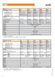
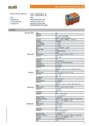
Model No. Nominal flow Mounting length Connection Energy unit Volume unit Sensor Pockets<br />
440M0600<br />
3<br />
1.5m /h 110mm G 3/4" (DN15) 0.1kWh<br />
3<br />
0.001m 0460R030 0460A206<br />
440M1000<br />
3<br />
2.5m /h 190mm G 1" (DN20) 0.1kWh<br />
3<br />
0.001m 0460R030 0460A206<br />
440M1600<br />
3<br />
6.0m /h 260mm G 1-1/4" (DN25) 1kWh<br />
3<br />
0.01m 0460R531 0460A207<br />
Flange connection - Brass pipe<br />
3<br />
3<br />
440M2200 10m /h 300mm DN40 1kWh 0.01m 0460R531 0460A207<br />
Flange connection - Stainless Steel pipe<br />
3 3<br />
440X2400 15m /h 270mm DN50 1kWh 0.01m 0460R531 0460A207<br />
440X2600<br />
3<br />
25m /h 300mm DN65 1kWh<br />
3<br />
0.01m 0460R532 0460A208<br />
440X3000<br />
3<br />
40m /h 300mm DN80 0.001MWh<br />
3<br />
0.1m 0460R532 0460A208<br />
440X3400<br />
3<br />
60m /h 360mm DN100 0.001MWh<br />
3<br />
0.1m 0460R532 0460A208<br />
440X3600<br />
3<br />
100m /h 250mm DN125 0.001MWh<br />
3<br />
0.1m 0460R532 0460A208<br />
440X3800<br />
3<br />
150m /h 300mm DN150 0.001MWh<br />
3<br />
0.1m 0460R532 0460A208<br />
440X4200<br />
3<br />
250m /h 350mm DN200 0.1MWh<br />
3<br />
0.1m 0460R533 0460A209<br />
440X4400<br />
3<br />
400m /h 450mm DN250 0.1MWh<br />
3<br />
0.1m 0460R533 0460A209<br />
The tried and tested oscillating jet principle of Superstatic flow sensors in combination with Supercal 531<br />
integrators gurantess reliable, long-term metering of thermal energy and flow.<br />
Subject to technical changes V1.2 26022010<br />
1
Energy Meter<br />
Thermal energy meter<br />
Superstatic 440 + Supercal 531 + Temperature sensor<br />
Distributed by <strong>Belimo</strong><br />
Design<br />
Temperature sensor pair<br />
Measurement technique<br />
Functional description<br />
The energy meter consists of a Superstatic 440 flow sensor, a Supercal 531<br />
(AC 24V) integrator and a pair of temperature sensors. Consumption values<br />
can be read easily on display.<br />
Supercal 531 integrator in combination with Superstatic flow sensor are supplied<br />
as standard in Pt500 version. The temperature sensors are matched to one<br />
another. They are always supplied in pairs and must not be separated, extended<br />
or shortened. In the case of a temperature sensor paired with a cable longer than<br />
3m, we recommend the exclusive use of screened temperature sensor pairs. In<br />
this case, the screening must be fitted correctly.<br />
The Supercal 531 with AC 24V power supply records the supply and the return<br />
temperature every 3 seconds. The recording flow rate is dependent on the pulse<br />
value of the flow sensor unit and is constantly updated. From the mean flow rate,<br />
the temperature difference and the heat coefficient will calculate the energy of<br />
the captured medium and display on the 8-digit LCD.<br />
The top level of Superstatic flow sensors is always the sensor level with feedback<br />
loops. The sensor frequency / pulses are directly proportional to the flow / volume.<br />
The oscillating jet level has an acceleration section with interactive action. The<br />
oscillate frequency of the oscillating jet and the electrical signals generated do not<br />
need any external energy source.<br />
The water inlet and outlet have a fluid input optimised for flow and an integrated<br />
straight section, which makes an external straight section up to DN40 redundantly.<br />
Subject to technical changes V1.2 26022010<br />
2
Energy Meter<br />
Distributed by <strong>Belimo</strong><br />
Main features<br />
Superstatic flow sensors are optimised for the measurement and calculation of<br />
energy consumption in cooling and heating systems. They are also extremely<br />
well suited to use purely as volumetric flow meters for various media.<br />
- Interchangeable measuring head<br />
3<br />
- Comprehensive range 1-400m /h<br />
- Purchase and maintenance costs are reasonable compared with other static<br />
flow sensors.<br />
- Corrosion resistant materials<br />
- Threaded and flange connection<br />
- No straight sections necessary up to DN40<br />
- No moving parts, therefore no wear<br />
- Not sensitive to dirt<br />
- Durable<br />
- Can be installed anywhere<br />
3<br />
- Common spare parts 1-400m /h<br />
3<br />
- Dynamic range 1:50 for qp 40-400m /h<br />
3<br />
1:100 for qp 1-40m /h<br />
- Direct pick-up of voltage pulses<br />
- Measurement irrespective of medium<br />
- Long-term, stable, accurate and reliable measurement, even if water quality is<br />
poor.<br />
Ordering<br />
Design<br />
When placing an order for energy meters you must indicate the normal flow used for<br />
heating or cooling and mounting place (supply or return).<br />
The Supercal 531 integrator is suitable for connection with Pt 500 temperature sensor<br />
pairs with 2- or 4-conducting wires techniques. Volume inputs can be combined with<br />
3<br />
mechanical, magnetic-inductive, ultrasonic or fluidic oscillators flow sensors with a<br />
maximum nominal flow rate of 10,000m /h. The factor of the pulse value is defined<br />
in the flow meter unit. The volume input value is defined when the unit is produced.<br />
The pulse value can be modified by means of the push button. The additional pulse<br />
inputs allow the connection of hot water, cold water, gas, oil and electricity meters.<br />
Consumption values can be read easily on the LCD display or via the M-bus.<br />
Power supply module The power supply of the Supercal 531<br />
- AC 24V 50/60Hz<br />
Communication module<br />
Built-in M-bus module.<br />
Subject to technical changes V1.2 26022010<br />
3
Energy Meter<br />
Distributed by <strong>Belimo</strong><br />
Data storage<br />
In case of power failure, the Supercal 531 has two non-volatile EEPROM for<br />
extensive data safety storage. In both EEPROM the data is updated every hour.<br />
The first non-volatile memory is located inside on the printed circuit board of the<br />
relevant calibration and measurement part of the integrator and stores the<br />
following data:<br />
- Parameters of the integrator and configuration parameter<br />
- Cumulated energy<br />
- Cumulated volume<br />
- Customer’s specific tariff<br />
- 15 monthly values<br />
- 32 maximum values<br />
- 32 average values<br />
- Two set day<br />
- Cumulated energy or volume on the set day<br />
- Operating hour<br />
- Date and time<br />
- MET serial number (integrator upper part, calibration and measurement part)<br />
- Pulse value of the flow meter<br />
The second non-volatile EEPROM is located on the printed circuit board in the<br />
integrator base part and stores the following parameters:<br />
- MIO serial number (integrator base part, printed circuit board)<br />
- Identification number and customer number<br />
- Pulse value of additional meters 1 and 2<br />
- Cumulated values of additional meters 1 and 2<br />
- Unit of additional meters 1 and 2<br />
- M-bus address<br />
- Baud rate (M-bus)<br />
- Pulse value of the pulse output<br />
- Parameter setting of the analogue outputs<br />
- Alarm and threshold value<br />
This EEPROM ensures a smooth exchange of the calibration and measurement<br />
relevant part, without a new entering of the configuration of the communication.<br />
Cumulated energy<br />
For energy unit displayed in kWh/MWh. The maximum energy that can be<br />
displayed is 99,999,999; the number of decimals can be set at the factory or by<br />
an authorised calibration laboratory.<br />
Backup<br />
For examination and safety storage of the measurement results the Supercal<br />
stores all data in a non-volatile memory once per hour. With power supply failure<br />
all values are automatically updated and stored.<br />
Test segment<br />
Shown on the LCD display.<br />
Subject to technical changes V1.2 26022010<br />
Cumulated volume<br />
Operating hours<br />
3<br />
Displayed in m . The maximum displayable energy is 9,999,999.9, the number<br />
of decimals can be set at the factory or by an authorised calibration laboratory.<br />
Displayed in hours.<br />
4
Energy Meter<br />
Distributed by <strong>Belimo</strong><br />
Error time<br />
Flow rate<br />
Supply and return<br />
temperature<br />
Temperature difference<br />
Power<br />
The cumulated time, while some error was present, is indicated in minutes.<br />
3<br />
The current flow rate is displayed in m /h , the number of decimals can be<br />
set at the factory or by an authorised calibration laboratory.<br />
The temperature is displayed with one decimal. Temperatures under 0 C<br />
o<br />
are shown with a “ - ” (minus) sign. The display range is -20...200 C.<br />
The temperature difference is displayed with two decimals. If the return<br />
temperature is higher than the supply temperature, a “ - ” (minus) sign will be<br />
placed in front.<br />
The standard unit displayed in kWh/MWh.<br />
o<br />
Set day values<br />
The Supercal 531 has two set days. On set day the cumulated energy, volume<br />
and pulse inputs are stored by date.<br />
Monthly values<br />
The storage date for the 15 months’ values can be set. The cumulated energy,<br />
volume, auxiliary pulse inputs and tariff values are stored. The storage date of<br />
the monthly values can be set, if the parameter settings mode is activated.<br />
Average values For the period of the 32 average values an integration time from 1 minute to 45<br />
days can be chosen. The average value for the actual power, flow, supply and<br />
return temperature, temperature difference, impulse input A1 and A2 are<br />
displayed on the LCD.<br />
Maximum value<br />
The precise monitoring and recording of power drops can be parameterised in<br />
1-hour cycles and cycles up to 1 year. The maximum values for the actual<br />
power, flow, supply and return temperature, temperature difference, impulse<br />
input A1 and A2 are displayed on the LCD.<br />
Pulse parameters<br />
The pulse values for the flow meter, for the additional meters A1 and A2 and<br />
the pulse values are displayed in the configuration menu.<br />
Identification number<br />
Date and time<br />
The identification/customer number is displayed with 8 digits. The identification/<br />
customer number can be changed via the push buttons, if the parameter setting<br />
mode is activated.<br />
The date and time are displayed in the different menus. The date with the index<br />
DA and the time with Hr are displayed. There is no differentiation between<br />
summer and winter time. Thanks to the backup function and in case of power<br />
supply loss the date and time update itself for several months. The date and the<br />
time can be changed via the push buttons, if the parameter setting mode is<br />
activated.<br />
o<br />
Pt500 resistance values The resistance value is 500ohm at 0 C.<br />
Subject to technical changes V1.2 26022010<br />
Primary address<br />
The primary address is displayed on the LCD. The primary address can be<br />
changed via the push buttons, if the parameter setting mode is activated.<br />
5
Energy Meter<br />
Distributed by <strong>Belimo</strong><br />
Communication<br />
Threshold values<br />
Status message<br />
transistor outputs<br />
Solar and cooling<br />
installations<br />
Cooling energy<br />
Communication is displayed by means of an indicator. The indicator enables one<br />
to recognise whether the integrator calculates or communicates from the inside<br />
or the outside.<br />
Two threshold values can be set over the optical interface or over the display and<br />
the push buttons. The following internal values can be used for the definition of<br />
thresholds: current flow, current power, supply or return temperature, temperature<br />
difference as well as a time window consisting of date and time. A threshold can<br />
also be activated when an error appears.<br />
The Supercal 531 allows a locking of status messages on the transistor outputs.<br />
The conditions of the status can be defined with the threshold values. An alarm<br />
output for fast and exact external monitoring of the operating conditions can be<br />
generated.<br />
The integrator units calibrated for water also ensure a precise measurement with<br />
glycol mixtures, as the average mixing ratio can be customised over the optical<br />
interface. The Supercal 531 also processes and computes negative<br />
temperatures. The dust and splash proof water-protected housings, IP65, are<br />
especially suitable for cooling installations. For these customised mixing ratios<br />
no official approvals are possible.<br />
The cooling energy is cumulated, if at the same time the two following conditions<br />
are fulfilled:<br />
( t) temperature difference >-0.2K<br />
o<br />
as well as the supply temperature
Energy Meter<br />
Distributed by <strong>Belimo</strong><br />
Display<br />
In consideration of the person reading the LCD display of the Supercal 531, the<br />
display is arranged clearly and is particularly large.<br />
index for average and<br />
maximum value<br />
Service level<br />
communication indication<br />
index for tariff 1 high temperature output<br />
and tariff 2<br />
input<br />
low temperature<br />
flow indication<br />
index for the monthly,<br />
average and maximum<br />
values<br />
unit<br />
display figures<br />
frame for decimal<br />
figures<br />
index for menu guidance<br />
The display sequences are divided into the following menus:<br />
- Main menu<br />
- Set days<br />
- 15 monthly values<br />
- 32 average values<br />
- 32 maximum values<br />
- Configuration<br />
- Service information<br />
- Test and parameter setting level<br />
The display sequence can be customised. The two push buttons enable simple<br />
and customer friendly usage and readout of measurement data.<br />
Control concept With the command push button the different display levels or the<br />
display within the display level can be selected.<br />
By pressing the enter push button a display level or one of the<br />
submenus can be selected. Afterwards the individual displays<br />
within the display level or within the submenu can be selected<br />
with the command push button. If the command push button<br />
and the enter push button are pressed at the same time, then<br />
the display switches back again to the selection level of the<br />
different display levels.<br />
Subject to technical changes V1.2 26022010<br />
Operating mode<br />
The integrator Supercal 531 works in principle in normal mode. The following<br />
additional operating modes are integrated in the integrator’s software:<br />
- Test mode (without damaging the seal)<br />
- Parameterisation mode (user seal to be removed)<br />
- Verification mode (verification seal to be removed)<br />
The integrator Supercal 531 is fully parameterised at the factory and according<br />
to the country specific parameter settings. Authorised laboratories offices may<br />
modify the factory parameters.<br />
7
Energy Meter<br />
Distributed by <strong>Belimo</strong><br />
Error messages<br />
The Supercal 531 displays the Err-sign on the LCD, together with a number<br />
code of the occurring errors. When several errors occur at the same time the<br />
numbers of the error code are summed up; e.g Err3 = Err1 + Err2.<br />
Err1<br />
Supply sensor is short circuited or disconnected<br />
Err2<br />
Return sensor is short circuited or disconnected<br />
Err4<br />
Flow rate too high<br />
Err8<br />
Storage error EEPROM in the integrator unit - lower part<br />
(only after the second time active)<br />
Err16 Storage error EEPROM in measuring and calibration relevant part<br />
(only after the second time active)<br />
Err32 Configuration error EEPROM in measuring and calibration relevant<br />
part<br />
Err64 Configuration error EEPROM in the integrator unit - lower part<br />
Err128 Error of internal electronic, return to the manufacturer<br />
Err256 Voltage failure<br />
Err512 Defect of communication module, module location 1<br />
Err1024 Defect of communication module, module location 2<br />
Err2048 Error impulse input auxiliary meter A1<br />
Err4096 Error impulse input auxiliary meter A2<br />
Err8192 Error of internal electronic, return to the manufacturer<br />
If an error displays for more than one hour, it is stored in the error memory with the<br />
date it occurred, the time error comnmenced and the duration (in minutes). If an<br />
error stays less than 60 minutes, it is deleted automatically and without storage.<br />
The two temperature sensor indicators are displayed as a message with the<br />
cumulated energy display on the main menu, indicating if:<br />
- The temperature sensors are interchanged >> this condition arises with most<br />
installations during the summer time.<br />
- The temperature in the colder line is higher than in the warmer line.<br />
All error messages are deleted automatically on the LCD, 30 seconds after the<br />
error correction.<br />
Subject to technical changes V1.2 26022010<br />
Optical interfaces The integrator Supercal 531 has an optical interface according to EN 61107.<br />
The M-Bus protocol according to EN 1434. The optical interface corresponds<br />
electrically and mechanically to the ZVEI IEC 1107 standard. Following start-up<br />
and service work, it allows:<br />
- Readout of all values<br />
- Parameterisation<br />
- Tests<br />
Communication options<br />
Open collector outputs<br />
Resolution of the<br />
impulse input and output<br />
The Supercal 531 differentiates between standard option possibilities equipped at<br />
the factory and optional plug-in communication modules. The Supercal 531 has<br />
two plug-in spaces for all kinds of optional communication modules foreseen. The<br />
integrator unit recognises the optional modules approximately 10 seconds after<br />
plug-in - the functions are freely available.<br />
The Supercal 531 has as a standard two Open Collector outputs for energy,<br />
volume, tariff 1, tariff 2, alarm and threshold values. These outputs are not<br />
galvanically separated.<br />
Optionally, two galvanically separated Open Collector output modules for standard<br />
or high-speed impulse outputs are available. The high-speed impulse can be used,<br />
for example, for the control of a valve. The impulse type and pulse duration can be<br />
set over the optical interface or with the help of the control push button.<br />
The set resolution as well as the unit of the impulse input and output are seen on<br />
the display menu - configuration.<br />
8
Energy Meter<br />
Distributed by <strong>Belimo</strong><br />
<strong>Technical</strong> data<br />
Flow sensor<br />
3<br />
1.5 - 6.0m /h (DN15 - 25)<br />
Model No . 440M0600 440M21000 440M1600<br />
DN<br />
Threaded connector<br />
15<br />
3/4”<br />
20<br />
1”<br />
Nominal flow qp 1.5 2.5<br />
Maximum flow qs 3.0 5.0<br />
Minimum flow qi 15 25<br />
Pulse value at qp 27.5 27.5<br />
Mounting length 110 190<br />
Weight 1.8<br />
3.2<br />
Standard<br />
EN 1434 Class 2 (+/- 2% at qp)<br />
Nominal pressure PN 16<br />
Pressure loss at qp 0.09<br />
0.25<br />
25<br />
1-1/4”<br />
6.0<br />
12<br />
60<br />
8.20<br />
260<br />
4.3<br />
0.16<br />
DN<br />
G<br />
3<br />
m /h<br />
3<br />
m /h<br />
l/h<br />
imp/l<br />
mm<br />
kg<br />
bar<br />
bar<br />
3<br />
Flow sensor 10 - 25m /h (DN40 - 65)<br />
Model No . 440M2200 440X24000 440X2600<br />
DN<br />
40 50<br />
Nominal flow qp 10 15<br />
Maximum flow qs 20 30<br />
Minimum flow qi 100 150<br />
Pulse value at qp 5.15 3.15<br />
Mounting length 300 270<br />
Weight 7.0<br />
12.2<br />
Standard<br />
EN 1434 Class 2 (+/- 2% at qp)<br />
Nominal pressure PN 16<br />
Pressure loss at qp 0.25 0.25<br />
65<br />
25<br />
50<br />
250<br />
1.93<br />
300<br />
12.8<br />
0.25<br />
DN<br />
3<br />
m /h<br />
3<br />
m /h<br />
l/h<br />
imp/l<br />
mm<br />
kg<br />
bar<br />
bar<br />
3<br />
Flow sensor 40- 100m /h (DN80 - 125)<br />
Model No . 440X3000 440X3400 440X3600<br />
DN<br />
80 100<br />
125<br />
Nominal flow qp 40 60<br />
100<br />
Maximum flow qs 80 120<br />
200<br />
Minimum flow qi 800 1200<br />
2000<br />
Pulse value at qp 0.82 0.55<br />
0.33<br />
Mounting length 300 260<br />
250<br />
Weight 13.5<br />
14.6<br />
16.0<br />
Standard<br />
EN 1434 Class 2 (+/- 2% at qp)<br />
Nominal pressure PN 16<br />
Pressure loss at qp 0.09 0.10<br />
0.10<br />
DN<br />
3<br />
m /h<br />
3<br />
m /h<br />
l/h<br />
imp/l<br />
mm<br />
kg<br />
bar<br />
bar<br />
3<br />
Flow sensor 150- 1500m /h (DN150 - 500)<br />
Subject to technical changes V1.2 26022010<br />
Model No . 440X3800 440X42000 440X4400 *440X5000<br />
DN<br />
150 200<br />
250<br />
500<br />
Nominal flow qp 150 250<br />
400<br />
1500<br />
Maximum flow qs 300 500<br />
800<br />
3000<br />
Minimum flow qi 3000 5000<br />
8000<br />
15000<br />
Pulse value at qp 0.22 0.14<br />
0.09<br />
0.028<br />
Mounting length 300 350<br />
450<br />
500<br />
Weight 26.0<br />
30.0<br />
57.0<br />
130<br />
Standard<br />
EN 1434 Class 2 (+/- 2% at qp)<br />
Nominal pressure PN 16<br />
10<br />
Pressure loss at qp 0.10 0.10<br />
0.10<br />
0.10<br />
*440X5000 Steel pipe coated<br />
DN<br />
3<br />
m /h<br />
3<br />
m /h<br />
l/h<br />
imp/l<br />
mm<br />
kg<br />
bar<br />
bar<br />
9
Energy Meter<br />
Distributed by <strong>Belimo</strong><br />
<strong>Technical</strong> data<br />
Integrator<br />
-------------------------------------------------------------------------<br />
STANDARD VERSION<br />
-------------------------------------------------------------------------<br />
Temperature measurement<br />
Pt500<br />
2 wires<br />
Absolute temperature range<br />
-20...180°C<br />
Homologation range<br />
2...150K<br />
Temperature resolution t<br />
0.1 K<br />
Temperature resolution t<br />
0.01 K<br />
Measuring precision better than EN 1434-1 request<br />
2 pulse outputs<br />
Open collector outputs are polarised and not separated<br />
from the ground. They have to be connected to external<br />
‘pull-up’ resistor.<br />
The outputs provide to an external system the possibility<br />
to totalise the energy and volume calculated in the<br />
integrator or other values related to the configuration<br />
settings.<br />
Measuring cycle<br />
Temperature measurement:<br />
- 3 seconds when mains operated<br />
Volume measurement:<br />
- Pulse volume is constantly updated<br />
Ambient temperature<br />
Operation<br />
Storing and transport<br />
Display<br />
5...55°C<br />
-25...70°C<br />
8 digit LCD<br />
OC class :<br />
allows connection to IB class(EN1434-2:1997prA1) inputs<br />
f max = 5 Hz (+60% / -20%)<br />
OD+ class:<br />
allows connection to fast inputs<br />
f max = 10 kHz (+60% / -20%)<br />
Subject to technical changes V1.2 26022010<br />
Display units<br />
Energy<br />
kWh/MWh<br />
Volume m 3<br />
Additional pulse inputs<br />
volume or energy<br />
Temperature<br />
°C<br />
Input voltage<br />
Voltage<br />
Rated current<br />
AC 24V supply<br />
AC 24V 50/60Hz<br />
Data security<br />
Verification and measurement relevant part EEPROM<br />
Integrator base<br />
EEPROM<br />
6<br />
EEPROM size<br />
8Kb, 10 writing cycle<br />
Housing protection<br />
Standard<br />
IP54<br />
Pulse input<br />
Input frequency<br />
Normal mode<br />
Fast mode<br />
Battery operation<br />
Mains operation<br />
Input voltage<br />
Volume pulse inputs<br />
M-Bus<br />
Fixed or variable data structure<br />
Potential free, reverse battery proof<br />
Baud rate 300...9600 baud<br />
800mA<br />
max. 5Hz<br />
max. 12kHz<br />
max. 5kHz<br />
max. 12kHz<br />
0 - 30V<br />
1-10-100-1000 l/pulse<br />
or 2.5-25-250-2500 l/pulse<br />
U+<br />
0V<br />
Outputs<br />
531<br />
t1<br />
16<br />
18<br />
17<br />
1 / f<br />
t2<br />
Iout<br />
Vout<br />
Electric specifications EN1434-2 :1997prA1<br />
tm<br />
Counter 1<br />
External equipment<br />
Contact<br />
Off<br />
Counter 2<br />
t1<br />
Contact<br />
On<br />
Vout max
Energy Meter<br />
Distributed by <strong>Belimo</strong><br />
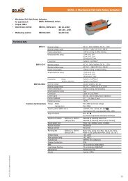
<strong>Technical</strong> data - temperature sensor 4 wire (optional)<br />
Temperature sensor 84 - 174mm, diameter 6mm, 4-wire<br />
Standard versions temperature sensors<br />
Sensor<br />
0460R850<br />
0460R851<br />
0460R852<br />
0460R853<br />
0460R854<br />
0460R855<br />
Element<br />
Pt500<br />
Pt500<br />
Shielding<br />
DIN 43765<br />
DIN plastic<br />
Wire<br />
4-wire<br />
4-wire<br />
84<br />
84<br />
Measuring element:<br />
Mating:<br />
Measuring range:<br />
Connection:<br />
Connection head<br />
Circuit:<br />
Material:<br />
Nominal pressure:<br />
Pocket:<br />
Pt 500 platinum resistor according to DIN IEC 751<br />
Computer-paired in accordance with CEN 1434<br />
Standard version 0°C…150°C (0°C…180°C with connection head)<br />
2-wire cable or 4-wire cable<br />
Plastic, cable entry PG9 with sealable cover, IP53, or<br />
Aluminum DIN 43765 form B, cable entry PG16, IP54<br />
Standard version in 4-wire technology<br />
Sensor pipe, stainless high-grade steel 1.4571<br />
Sensor PN16, protection pocket PN25<br />
Stainless high-grade steel 1.4571 with high pressure-safe squeezing ring<br />
connection<br />
2-wire connection without connection head<br />
In this most usual connection circuit, the resistance of the cable is to be added to the resistance of<br />
the sensor. For the heat measurement, not the absolute temperature is important, but the exact<br />
temperature difference, therefore both sensor cables must be identical length (resistance). The<br />
sensors are exactly computer-paired at the factory and may be used only in the original mating.<br />
4-wire connection with connection head<br />
Through wire 1 and 2 are constant current value flows. Through wire 5 and 6, the voltage changes<br />
of the Pt resistance is measured. In this connection circuit type, sensors with larger or unequal cable<br />
length can be used, since the resistance of the wire has no influence.<br />
Diagram for connections of temperature sensors<br />
higher<br />
temperature<br />
lower<br />
temperature<br />
higher<br />
temperature<br />
lower<br />
temperature<br />
higher<br />
temperature<br />
lower<br />
temperature<br />
higher<br />
temperature<br />
lower<br />
temperature<br />
Subject to technical changes V1.2 26022010<br />
2-wire sensor<br />
4-wire sensor<br />
4-wire sensor<br />
for 2-wire connection<br />
4-wire sensor<br />
11
Energy Meter<br />
Distributed by <strong>Belimo</strong><br />
<strong>Technical</strong> data - temperature sensor 4 wire (optional)<br />
2-wire connection<br />
Measuring result = Resistance Pt500 + cable resistance<br />
4-wire connection<br />
Measuring result = Resistance Pt500 + cable resistance<br />
The cable resistance is not to be considered with 4-wire technology<br />
Characteristics of the temperature sensors according to DIN IEC751<br />
1000.0000<br />
Class B<br />
900.0000<br />
800.0000<br />
Pt100<br />
Pt500<br />
Difference<br />
Class A<br />
Widerstand Resistance [Ohm]<br />
700.0000<br />
600.0000<br />
500.0000<br />
400.0000<br />
300.0000<br />
200.0000<br />
100.0000<br />
0.0000<br />
-100.0 -80.0 -60.0 -40.0 -20.0 0.0 20.0 40.0 60.0 80.0 100.0 120.0 140.0 160.0 180.0 200.0<br />
Temperatur [°C]<br />
Insulation in accordance with SIA<br />
Temperature sensor overall lengths in dependence of the pipe diameters and thickness of<br />
the thermal insulation in accordance with SIA (Schweizerischer Ingenieur- und<br />
Architektenverein - Swiss engineer and architect association)<br />
Subject to technical changes V1.2 26022010<br />
Pipe<br />
Insulation thickness D<br />
with temperature<br />
difference K<br />
K< K40- K><br />
Welding sleeve<br />
Sensor and<br />
protection<br />
pocket<br />
nominal<br />
length<br />
Nominal size<br />
Outside<br />
40°C 80°C 80°C<br />
d l<br />
mm inch mm D mm D mm D mm inch mm mm<br />
15 1/2 21,3 30 40 50 3/8 1/2 20 31 33<br />
20 3/4 26,9 40 40 50 3/8 1/2 20 31 33<br />
25 1 33,7 40 50 --- 3/8 1/2 20 31 33<br />
25 1 33,7 --- --- 60 1/2 60 84<br />
32 1 1/4 42,4 40 50 60 1/2 60 84<br />
40 1 1/2 48,3 40 50 60 1/2 60 84<br />
50 2 60,3 50 60 60 1/2 60 84<br />
65 2 1/2 76,1 50 60 --- 1/2 60 84<br />
65 2 1/2 76,1 --- --- 80 1/2 80 134<br />
80 3 88,9 50 60 80 1/2 80 134<br />
100 4 114,8 60 80 80 1/2 80 134<br />
125 5 139,7 80 80 80 1/2 80 134<br />
150 6 165,1 80 80 100 1/2 80 174<br />
200 8 219,1 80 80 100 1/2 80 174<br />
12
Energy Meter<br />
Distributed by <strong>Belimo</strong><br />
<strong>Technical</strong> data - temperature sensor 4 wire (optional)<br />
Thermal insulation<br />
For more accurate temperature measurement, thermal insulation should be installed.<br />
Permissible insulation<br />
The insulation should never cover the temperature sensor cable.<br />
Installation recommendations according to EN1434<br />
Subject to technical changes V1.2 26022010<br />
13
Energy Meter<br />
Accessory - Optical Probe<br />
531OP-U<br />
531OP-U<br />
Infra-red optical probe for meter reading<br />
Description<br />
The optical probe 531OP-U enables data transfer<br />
between devices equipped with optical<br />
communication port confirmed to IEC 1107<br />
and terminals quipped with USB port.<br />
<strong>Technical</strong> Data<br />
Optical Standard EN 62056 (IEC 1107)<br />
Baud Rate<br />
Transfer<br />
Power Supply<br />
Current<br />
Dimensions<br />
50 - 115K<br />
Half duplex<br />
5V by USB interface<br />
approx. 30mA<br />
Diameter 32mm, height 22mm<br />
Cable Length 1.2m<br />
Weight<br />
Magnetisation<br />
Case Material<br />
approx. 65g include cable and connector<br />
North pole outwards, strength approx. 15N<br />
Delrin / POM<br />
Application<br />
Through the optical probe and Program 531(can be download from our website),<br />
we can change settings ;-<br />
Date, time, ID number, set days, M-bus primary address, baud rate, output pulse<br />
factors, tariff settings, customised menu......etc.<br />
Connect location<br />
Subject to technical changes V1.2 12042010<br />
14
Energy Meter<br />
Distributed by <strong>Belimo</strong><br />
Safety<br />
Local prescriptions<br />
Power supply<br />
Lightning protection<br />
Bus installations<br />
Cooling installations<br />
Mounting<br />
Security seals<br />
The integrator Supercal 531 is made reliable by using state-of-the-art<br />
techniques and according to heat meter standards. If the integrator unit is operated<br />
outside of the specifications described herein or is not handled in accordance with<br />
regulation, then all service and guarantee claims towards the company Sontex are<br />
void.<br />
Following must be observed:<br />
- Local regulations for electrical installations<br />
- Local regulations for the use of energy meters<br />
- Mounting information for the installation of energy meters and temperature<br />
sensors according to EN1434-2 and EN1434-6.<br />
In order to guarantee stable power supply, an uninterruptible power supply should<br />
be provided.<br />
- Local regulations for electrical installations must be guaranteed.<br />
- Over voltage 10% or under voltage 10% are unacceptable.<br />
Preventive measures against lightning must be taken within the mains supply or<br />
bus system.<br />
With all bus installations, a galvanic separation must be ensured on the part of the<br />
flow sensors. Otherwise the integrator unit can be destroyed!<br />
Isolation regulations must be observed. Generally the integrator is to be mounted<br />
away from the cooling pipe.<br />
As standard, the mounting instructions are delivered with the integrator and must<br />
be observed for the installation and the start up. Temperature sensor with a cable<br />
length longer than 3m, we recommend the use of shielded cables. The shielding<br />
must be connected appropriately with the enclosed fixing clips.<br />
All integrator units are to be provided with the necessary seals, so that the<br />
equipment is protected against unauthorised access. Calibration relevant seals<br />
may not be damaged or removed! Otherwise, all guarantees and service warranties<br />
will no longer apply, as well as the validity of the calibration. For service purpose,<br />
only authorised personnel may remove user sercurity seals.<br />
Service and repairs<br />
Only laboratories authorised by Sontex may only carry out the service and repair<br />
work.<br />
Subject to technical changes V1.2 26022010<br />
15
Energy Meter<br />
Distributed by <strong>Belimo</strong><br />
Wiring diagram<br />
TEMP H<br />
TEMP L<br />
5 6 7 8<br />
TEMP H TEMP L OSCILLATOR IN1 IN2 OUT1 OU T2 M -B us<br />
AC 24V<br />
1 2 3 4 10 11 9 50 51 52 53 16 17 18 24 25<br />
L<br />
N<br />
+ _ +Vdc<br />
+ _ + _ + _ +<br />
White Green Brown<br />
Pulse output<br />
(Energy) (Volume)<br />
AC 24V<br />
Oscillator<br />
M-Bus controller<br />
2-wire<br />
Temperature sensor<br />
(Higher side)<br />
RS 232 cable<br />
2-wire<br />
Temperature sensor<br />
(Lower side)<br />
Computer / other BMS<br />
Subject to technical changes V1.2 26022010<br />
16
Energy Meter<br />
Distributed by <strong>Belimo</strong><br />
Dimensions<br />
Integrator Dimensions [mm]<br />
531 110 x 138.7 x 45.3<br />
o<br />
Sensor Dimensions Wires Cable length Element [500ohm at 0 C]<br />
0460R530 o 6 x 33mm 2 2m Pt500<br />
0460R531 o 6 x 85mm 2 2m<br />
Pt500<br />
0460R532 o 6 x 134mm 2 2m<br />
Pt500<br />
0460R533 o 6 x 173mm 2 2m<br />
Pt500<br />
Plastic head<br />
Aluminum head<br />
9<br />
84<br />
84<br />
173<br />
215<br />
Sensor Dimensions Wires Head Element [500ohm at 0 C]<br />
0460R850 o 6 x 84mm 4 Aluminum<br />
Pt500<br />
0460R851 o 6 x 134mm 4 Aluminum<br />
Pt500<br />
0460R852 o 6 x 174mm 4 Aluminum<br />
Pt500<br />
0460R853 o 6 x 84mm 4 Plastic<br />
Pt500<br />
0460R854 o 6 x 134mm 4 Plastic<br />
Pt500<br />
0460R855 o 6 x 174mm 4 Plastic<br />
Pt500<br />
o<br />
Cable<br />
cable400<br />
Type<br />
4-wire shield cable<br />
Length<br />
on request<br />
Pocket<br />
Dimensions<br />
Subject to technical changes V1.2 12042010<br />
0460A206<br />
0460A207<br />
0460A208<br />
0460A209<br />
o 6 x 52 x G 1/2”<br />
o 6 x 111.5 x G 1/2”<br />
o 6 x 161.5 x G 1/2”<br />
o 6 x 201.5 x G 1/2”<br />
17
Energy Meter<br />
Distributed by <strong>Belimo</strong><br />
Dimension<br />
Flow sensor Superstatic 440<br />
Cable length 3m<br />
Fig. 1 Fig. 2 Fig. 3<br />
qp DN G PN Fig. No B [mm] H [mm] L[mm]<br />
1.5 m 3 /h --- ¾” 16 1<br />
125 79 110<br />
2.5 m 3 /h --- 1” 16<br />
1<br />
125 79 190<br />
6 m 3 /h --- 1 ¼” 16 2 78 105 260<br />
10 m 3 /h 40 --- 16 3 150 157 300<br />
D<br />
d<br />
H<br />
h<br />
h<br />
h[mm]<br />
---<br />
---<br />
---<br />
110<br />
L<br />
Subject to technical changes V1.2 26022010<br />
qp DN PN L [mm] D [mm] d [mm] H [mm] h [mm]<br />
15 m 3 /h 50 16 270 165 53 176<br />
125<br />
25 m 3 /h 65 16 300 185 69 194<br />
176<br />
40 m 3 /h 80 16 300 200 81 208<br />
160<br />
60 m 3 /h 100 16 360 220 107 231<br />
180<br />
100 m 3 /h 125 16 250 250 132 258<br />
210<br />
150 m 3 /h 150 16 300 285 159 290<br />
240<br />
250 m 3 /h 200 16 350 340 207 343<br />
295<br />
400 m 3 /h 250 16 450 405 260 402<br />
355<br />
3<br />
1500 m /h<br />
500 10 500 670 510 670 620<br />
18
Innovation, Quality and Consultancy:<br />
A partnership for motorising HVAC actuators<br />
BELIMO Automation AG<br />
Brunnenbachstrasse 1<br />
8340 Hinwil, Switzerland<br />
Tel: +41 43 843 61 11<br />
Fax: +41 43 843 62 68<br />
E-mail: info@belimo.ch<br />
BELIMO <strong>Actuators</strong> (<strong>Shanghai</strong>) Trading Ltd.<br />
479 Chun Dong Road, Building C-2<br />
Xin Zhuang Industry Park<br />
<strong>Shanghai</strong> 201108, P.R. China<br />
Tel: +86 21 5483 2929<br />
Fax: +86 21 5483 2930<br />
E-mail: info.asiapacific@belimo.ch<br />
BELIMO Aircontrol (USA), Inc.<br />
43 Old Ridgebury Road<br />
Danbury, CT 06813-2928, USA<br />
Tel: +800 543-9038 / 203 791-9915<br />
Fax: +800 228-8283 / 203 791-9919
![SV24A-SZ-TPC_datasheet_en[2013.03.26].pdf - Belimo Actuators ...](https://img.yumpu.com/49758098/1/184x260/sv24a-sz-tpc-datasheet-en20130326pdf-belimo-actuators-.jpg?quality=85)


![CCV_V7[2013.07.16].pdf - Belimo Actuators (Shanghai)](https://img.yumpu.com/46161653/1/184x260/ccv-v720130716pdf-belimo-actuators-shanghai.jpg?quality=85)