![SY..[24.05.2013].pdf - Belimo Actuators (Shanghai)](https://img.yumpu.com/39236114/1/500x640/sy24052013pdf-belimo-actuators-shanghai.jpg)
SY..[24.05.2013].pdf - Belimo Actuators (Shanghai)
SY..[24.05.2013].pdf - Belimo Actuators (Shanghai)
SY..[24.05.2013].pdf - Belimo Actuators (Shanghai)

You also want an ePaper? Increase the reach of your titles
YUMPU automatically turns print PDFs into web optimized ePapers that Google loves.
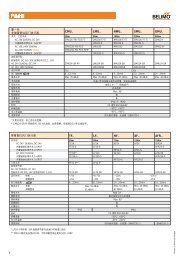
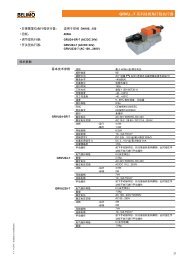
<strong>SY</strong>.. Large Torque Multi-function <strong>Actuators</strong><br />
• General Large Torque <strong>Actuators</strong><br />
for operation of:<br />
• Torque:<br />
• Open/Close or 3-point control:<br />
• Modulating control:<br />
DN50...600 Butterfly Valves<br />
35...3500Nm<br />
<strong>SY</strong>...24-3-T, <strong>SY</strong>...230-3-T<br />
<strong>SY</strong>1U24-SR-T, <strong>SY</strong>1U230-SR-T<br />
<strong>SY</strong>...U24-MF-T, <strong>SY</strong>...U230-MF-T<br />
Technical data<br />
Nominal voltage AC 24V ± 10%<br />
<strong>SY</strong>...-3-T, <strong>SY</strong>...-SR-T AC 230V ± 10%<br />
Nominal voltage range AC 21.6...26.4V<br />
<strong>SY</strong>...-3-T, <strong>SY</strong>...-SR-T 207...253V<br />
Connecting cable<br />
½” cable connector, screw terminals<br />
Motor protection<br />
H class insulation (<strong>SY</strong>1), F class insulation (<strong>SY</strong>2...12)<br />
Gear train<br />
High alloy steel gear sets<br />
Control signal Y<br />
DC (0)2...10V<br />
Sensitivity<br />
200mV<br />
Position feedback signal U DC (0)2...10V<br />
Angle of rotation<br />
Electrically limited to 90°, Max. 95° for manual operation<br />
Position indicator<br />
Top mounted domed indication<br />
Auxiliary switches 2xSPDT 3A, AC 230V(<strong>SY</strong>1); 2xSPDT 5A, AC 230V(<strong>SY</strong>2...12)<br />
Ambient temp.<br />
-20...+60°C<br />
Humidity<br />
5...95% RH, non-condensing<br />
Degree of protection IP67<br />
Housing material<br />
Die Cast Aluminium Alloy<br />
EMC<br />
CE according to 89/336/EEC<br />
Low voltage directive CE according to 73/23/EEC, 93/68/EEC<br />
* MP-T models available on request<br />
Model<br />
No.<br />
Nominal<br />
Torque<br />
(Nm)<br />
Product Feature<br />
Motor power Running time Running current<br />
Weight<br />
(kg)<br />
Mounting<br />
flange<br />
AC 24V AC 230V<br />
AC AC 230V AC AC Manual override<br />
24V 50Hz 60Hz 24V 230V<br />
<strong>SY</strong>1.. 35 10W 10W 15s 13s 12s 0.6A 0.3A by 8mm Wrench 2 F05<br />
<strong>SY</strong>2.. 90 70W 40W 15s 17s 15s 3.0A 0.5A Handwheel 11 F07<br />
<strong>SY</strong>3.. 150 70W 40W 22s 26s 22s 3.0A 0.5A Handwheel 11 F07<br />
<strong>SY</strong>4.. 400 180W 120W 16s 18s 16s 6.0A 0.6A Handwheel 22 F10<br />
<strong>SY</strong>5.. 500 180W 120W 22s 25s 22s 6.5A 0.7A Handwheel 22 F10<br />
<strong>SY</strong>6.. 650 / 120W / 31s 28s / 0.8A Handwheel 22 F10<br />
<strong>SY</strong>7.. 1000 / 180W / 55s 46s / 1.6A Handwheel 36 F14<br />
<strong>SY</strong>8.. 1500 / 220W / 55s 46s / 2.0A Handwheel 36 F14<br />
<strong>SY</strong>9.. 2000 / 180W / 70s 58s / 1.6A Handwheel 56 F16<br />
<strong>SY</strong>10.. 2500 / 220W / 70s 58s / 2.0A Handwheel 56 F16<br />
<strong>SY</strong>11.. 3000 / 250W / 70s 58s / 1.6A Handwheel 56 F16<br />
<strong>SY</strong>12.. 3500 / 300W / 70s 58s / 2.2A Handwheel 56 F16<br />
32<br />
Electrical connections<br />
Overload protection<br />
Manual operation<br />
All actuator control elements are wired to a terminal strip under the main cover. Remove<br />
the cover and insert the cables through the cable connector in order to reach the terminal<br />
strip. The connectors should be made according to the diagram. Before beginning this<br />
procedure, make sure that the power supply voltage is in accordance with the actuator’s<br />
name plate. After the terminal connections have been made, move the actuator manually<br />
to the half-open position and make a preliminary check of the wiring.<br />
If the real running torque exceeds the nominal torque, the overload protection will be<br />
functioned to prevent the motor overload.<br />
The manual operation is available by turning a handwheel of actuators (<strong>SY</strong>2...12) and<br />
using a 8mm wrench for <strong>SY</strong>1.<br />
V6. 05.2013 • Subject to modification
<strong>SY</strong>.. Large Torque Multi-function <strong>Actuators</strong><br />
Ordering sample<br />
<strong>SY</strong>4 U230 -MF -T<br />
With terminal only<br />
“-MF/SR”: Modulating control<br />
“-3”: Open/Close or 3-point control<br />
“U24”: 24V nominal voltage (modulating)<br />
“U230”: 230V nominal voltage (modulating)<br />
“-24”: 24V nominal voltage (Open/Close, 3-point)<br />
“-230”: 230V nominal voltage (Open/Close, 3-point)<br />
Model number<br />
eg.Modulating control<br />
<strong>SY</strong>2U230-MF-T<br />
Open/Close, 3-point control<br />
<strong>SY</strong>2-230-3-T<br />
2<br />
Wiring diagrams<br />
<strong>SY</strong>..-24-3-T<br />
Open/Close or 3-point control<br />
Terminal<br />
Auxiliary switch<br />
Notes:<br />
• Connection via safety isolating transformer.<br />
• Relays are needed in parallel connection of<br />
several actuators<br />
• “L” cannot be connected to terminal #3 and<br />
#4 simultaneously.<br />
• 30% duty cycle.<br />
!<br />
~ T<br />
AC 24V<br />
1 3 4 5 6 7<br />
H<br />
#1 Power supply Com/Neutral<br />
#3 Power supply Hot line for Open<br />
#4 Power supply Hot line for Close<br />
#5 Connect to Com/Neutral for<br />
fully open indication<br />
#6 Connect to Com/Neutral for<br />
fully close indication<br />
#7 Heater<br />
A B C E F<br />
S1 100%<br />
S2 0%<br />
<strong>SY</strong>1-24-3-T<br />
A BCD<br />
E F<br />
S1 100% S2 0%<br />
<strong>SY</strong>(2...4)-24-3-T<br />
<strong>SY</strong>..-230-3-T<br />
Open/Close or 3-point control<br />
Terminal<br />
!<br />
WARNING! Leakage current is<br />
possible (
<strong>SY</strong>.. Large Torque Multi-function <strong>Actuators</strong><br />
Wiring diagrams<br />
(continued)<br />
<strong>SY</strong>1U230-SR-T Modulating control Terminal<br />
!<br />
WARNING! Leakage current is<br />
possible (
<strong>SY</strong>.. Large Torque Multi-function <strong>Actuators</strong><br />
Dimensions [mm]<br />
øB<br />
D<br />
D<br />
A<br />
1)<br />
øB<br />
C<br />
øB<br />
C<br />
2<br />
C<br />
N-S<br />
E<br />
A<br />
F<br />
A<br />
F<br />
J<br />
øD<br />
G<br />
E<br />
øH<br />
G<br />
E<br />
øH<br />
G<br />
IxM<br />
øH<br />
N-S<br />
IxM<br />
N-S<br />
IxM<br />
<strong>SY</strong>1.. <strong>SY</strong>2/3.. <strong>SY</strong>4..6..<br />
C<br />
C<br />
D<br />
D<br />
N-S<br />
N-S<br />
øB<br />
øB<br />
A<br />
A<br />
F<br />
F<br />
E<br />
E<br />
øH<br />
J<br />
G<br />
J<br />
IxM<br />
øK<br />
øH<br />
øK<br />
IxM<br />
G<br />
<strong>SY</strong>7/8..<br />
<strong>SY</strong>9..12..<br />
1) For <strong>SY</strong>1U24(230)-SR-T, A is 183.<br />
2) For <strong>SY</strong>2(3)-230-3-T, A is 255.<br />
V6. 05.2013 • Subject to modification<br />
Dim<br />
Flange<br />
A B C D E Φ F G H I J K M N S<br />
Model No<br />
type<br />
<strong>SY</strong>1.. 150 1) 106 8 19 15 - 14 50 4 45° - M6 2 1/2 PS F05<br />
<strong>SY</strong>2/3.. 255 2) 181 326 208 30 123 17/22 70 4 - 90 M8 2 1/2 PS F07<br />
<strong>SY</strong>4..6.. 317 217 394 294 40 194 22/35 102 4 - 125 M10 2 1/2 PS F10<br />
<strong>SY</strong>7/8.. 406 217 347 336 45 295 36 140 4 45° 180 M16 2 1/2 PS F14<br />
<strong>SY</strong>9...12.. 564 256 455 392 57 395 36 165 4 45° 221 M20 2 1/2 PS F16<br />
35
<strong>SY</strong>.. Large Torque Multi-function <strong>Actuators</strong><br />
Circuit board set up<br />
!<br />
Disconnect power supply<br />
before changing the following<br />
settings.<br />
The words in bold are<br />
default settings.<br />
S1, S2 - for<br />
Input signal<br />
Input<br />
signal<br />
Output<br />
signal<br />
S3, S4, S5 - for<br />
Output signal<br />
<strong>SY</strong>1U24-SR-T<br />
•DIP switches setting<br />
Factory setting<br />
8 7 6 5 4 3 2 1<br />
S6 - Direction of<br />
Travel in response<br />
to the control<br />
Off<br />
On<br />
S7 and S8 - Actuator<br />
response to the<br />
control signal failure<br />
When signal<br />
fails<br />
S1 S2<br />
S3 S4 S5 Symbol S6<br />
S7 S8<br />
(0)2...10V Off On (0)2...10V On Off On<br />
90°<br />
Fully closed Off On<br />
Off<br />
Y<br />
4...20mA On Off<br />
Fully open On Off<br />
4...20mA Off On Off<br />
90°<br />
On<br />
1...5V Off Off<br />
Y<br />
Stop On On<br />
•SW1 sensitive switch<br />
Position “0”: Lowest sensitive, 0...90° divided into 17 steps.<br />
Position “1”: Highest sensitive, 0...90° divided into 80 steps.<br />
Prior to switch-on, make sure the input signal and voltage wiring are in<br />
accordance with the actuator name plate and Dip-switch setting.<br />
<strong>SY</strong>1U230-SR-T<br />
(Only available for <strong>SY</strong>1U24/230-SR-T)<br />
When you need to adjust the signal of modulating board,<br />
please adjust the VR1 and VR2:<br />
•<br />
•<br />
VR2 adjusts 4mA, 2V, 1V (Fully-closed)<br />
VR1 adjusts 20mA, 10V, 5V (Fully-open)<br />
Please turn the VR2 to the end by clockwise direction and<br />
input 4mA to modulating board. Then please slightly turn<br />
the VR2 by counter-clockwise direction about 3...6 times<br />
until the RED light keeps ON.<br />
Please turn the VR1 to the end by counter clockwise direction<br />
and input 20mA to modulating board. Then please<br />
slightly turn the VR1 by clockwise direction about 3...6<br />
times until the GREEN light keeps ON.<br />
Service Jack<br />
Connect to PC-Tool<br />
Service Jack<br />
Connect to PC-Tool<br />
<strong>SY</strong>(2...4)U24-MF/MP-T<br />
Position feedback potentiometer<br />
<strong>SY</strong>(2...12)U230-MF-T<br />
Direction switch<br />
Y2 standard<br />
Factory setting<br />
For modulating actuators, the potentiometer is a standard part.<br />
RA25Y<br />
Potentiometer points 1, 2, 3 are wired to terminal blocks 10, 9, 8.<br />
When the actuator is closed: 8, 9 5kΩ<br />
36<br />
Potentiometer<br />
9, 10 0kΩ<br />
When the actuator is open: 8, 9 0kΩ<br />
9, 10 5kΩ<br />
V6. 05.2013 • Subject to modification
<strong>SY</strong>.. Large Torque Multi-function <strong>Actuators</strong><br />
Travel cams TC..<br />
Only authorised and trained persons are<br />
allowed to change the settings.<br />
• TC1-for open position of limit switch<br />
(factory setting 90°).<br />
• TC2-for closed position of limit switch<br />
(factory setting 0°).<br />
• TC3-for open position of auxiliary switch<br />
(factory setting 87°).<br />
• TC4-for closed position of auxiliary switch<br />
(factory setting 3°).<br />
LS4<br />
LS3<br />
LS2<br />
LS1<br />
<strong>SY</strong>1-..actuator<br />
shaft<br />
TC4<br />
TC3<br />
TC2<br />
TC1<br />
The cams for adjusting the limit and auxiliary switches are accessible if the cover is removed.<br />
The LS2/LS1 limit switches interrupt the power supply to the motor and are controlled by means<br />
of the TC.. cams which rotate with the shaft. The LS4/LS3 auxiliary switches can optionally be<br />
connected for signalisation purposes. The actuator closes the valve when the shaft turns clockwise<br />
(CW) and opens the valve when the shaft turns counter clockwise (CCW).<br />
LS4<br />
LS3<br />
LS2<br />
LS1<br />
shaft<br />
<strong>SY</strong>2...12-..actuator<br />
TC4<br />
TC3<br />
TC2<br />
TC1<br />
2<br />
Relationship of auxiliary switches, limiting switches and limits of manual rotation angle<br />
• A stop screw for OPEN limiting<br />
• B stop screw for CLOSED limiting<br />
• C stop screw connection for manual operation<br />
The limits of manual operation is set at -2°...92° in the factory. The override handwheel turns the planetary<br />
gear by means of a worm wheel. The gear is stopped mechanically by the two stop screws A and B.<br />
Angle Range 1: Two auxiliary switches LS3 and LS4 are set at 3°...87° angle in the factory<br />
Angle Range 2: The two limit switches LS2 and LS1 are set at 0°...90° angle in the factory<br />
Angle Range 3: Two stop screws A and B are set at -2°...92° angle in the factory<br />
Fully Open/Closed position setting<br />
V6. 05.2013 • Subject to modification<br />
Fully Closed position (0%) setting<br />
Fully Open position (100%) setting<br />
1) Power on. The actuator will drive CW to closed position.<br />
2) Check whether disc of valve at fully closed position.<br />
3) Adjust travel cams TC2 and stop screws for closed limiting (see “Adjusting travel cams and stop screws”)<br />
1) Power on. The actuator will drive CCW to open position.<br />
2) Check whether disc of valve is at fully open position.<br />
3) Adjust travel cams TC1 and stop screws for open limiting (see “Adjusting travel cams and stop screws”)<br />
37
<strong>SY</strong>.. Large Torque Multi-function <strong>Actuators</strong><br />
Adjusting the TC and stop screws<br />
1. Loosen the corresponding stop screw;<br />
2. Loosen the travel cam to be re-adjusted with a 2.5mm hexagonal key;<br />
3. Turn the travel cam clockwise or counter clockwise with the hexagonal key as shown in the right<br />
diagram and initially tighten the cam;<br />
4. Check the full rotation of limit switch with power on;<br />
5. Tighten the travel cam after successful re-adjustment, otherwise repeat to do point 3 and 4 until<br />
the travel cam is successfully re-adjusted.<br />
6. When the motor stops at fully closed or open position, tighten the corresponding stop screw until it<br />
•<br />
•<br />
touches the gearbox, turn the stop screw cycle back and lock by a hexagonal key and a wrench (1<br />
turn of the stop screw corresponding to 2° angle of rotation around).<br />
The LS2/LS1 switches must always switch off the motor before the effect of stop screws.<br />
Perform an adaption after changing the position of the travel cam<br />
Adaption button<br />
TC1/TC3 ( CCW)<br />
Open<br />
TC1/TC3 (CW)<br />
TC 2/TC4 ( CCW)<br />
TC2/TC4 (CW)<br />
Current position<br />
Required position<br />
Close<br />
Installation guidelines<br />
Cautions of installation<br />
Maintenance<br />
Storage<br />
•<br />
•<br />
•<br />
•<br />
•<br />
•<br />
Check power supply before wiring.<br />
Replace housing cover immediately after making adjustments and make sure seal is secure. If water<br />
or dust is present, thoroughly dry and clean before replacing housing.<br />
The motor cannot be reversed and the actuator cannot be installed upside down.<br />
Be sure to keep it away from gas; do not use in explosive and chemical district.<br />
Power off before maintenance purpose.<br />
The Open/Close frequency of the electric actuator is restricted according to the duty cycle to avoid<br />
overheating.<br />
All actuators are lubricated with anti-high temperature lubricant for a long life and therefore require no<br />
special maintenance. The condition of the valve stem and its nut must be checked periodically to make<br />
sure they are clean and well lubricated. We recommend that a program of periodic maintenance should<br />
be drawn up for actuators that are operated infrequently.<br />
The actuator includes electrical equipment as well as grease lubricated gear stages. In spite of the<br />
weather proof enclosure, oxidation, jamming and other alterations are possible if the actuator is not<br />
correctly stored. The actuator should be stored under a shelter in a clean, dry place and protected<br />
from frequent changes in temperature. Avoid placing the actuators directly on the floor. The actuators<br />
are equipped with heat resistance, but it’s recommended to connect the actuators to the power supply,<br />
especially if storage area is humid. Check that the temporary sealing plug of the cable entries are well in<br />
place. Make sure that the covers and boxes are well closed to ensure weather proof sealing.<br />
FAQ<br />
38<br />
Conditions Possibilities Solutions<br />
Motor overheat Voltage abnormal Check by multimeter<br />
High working frequency<br />
Limit the working frequency<br />
Motor spindle is stuck or valve is too tight to move Replace the stuck assemblies or the valve.<br />
No operation<br />
The gear box stuck by stop screw<br />
Power supply or voltage abnormal<br />
Fuse blown<br />
Check and correct travel cam for evidence of loosening;<br />
inspect the stop screw setting by operating the handwheel<br />
manually.<br />
Check the power supply voltage with the identification<br />
plate.<br />
Check and replace the fuse as required (except for HW-<br />
CBPCB)<br />
Check if the motor is hot.The actuator will be available<br />
Tripping of motor thermal protective device again after the motor has cooled down. Solve the motor<br />
overheat problem.<br />
Running motor stops Power supply has short circuit Check wiring<br />
External object stuck in the pipe<br />
Take off the valve for cleaning<br />
Not fully opening/closing The fixing screw for travel cam is loose Re-adjust and tighten the travel cam<br />
The actuator is continually<br />
hunting<br />
Occasional fail in motor<br />
switched on or off<br />
The sensitivity setting is incorrect<br />
Power input of ”open” and ”close” simultaneously<br />
Adjust the sensitivity switch SW1 to increase the<br />
number (only for <strong>SY</strong>1..).<br />
Check if the external control switch is normal; relays are<br />
needed in parallel connection of several actuators<br />
V6. 05.2013 • Subject to modification

![SV24A-SZ-TPC_datasheet_en[2013.03.26].pdf - Belimo Actuators ...](https://img.yumpu.com/49758098/1/184x260/sv24a-sz-tpc-datasheet-en20130326pdf-belimo-actuators-.jpg?quality=85)


![CCV_V7[2013.07.16].pdf - Belimo Actuators (Shanghai)](https://img.yumpu.com/46161653/1/184x260/ccv-v720130716pdf-belimo-actuators-shanghai.jpg?quality=85)