Technical data sheet NV24A-MP-TPC - Belimo
Technical data sheet NV24A-MP-TPC - Belimo
Technical data sheet NV24A-MP-TPC - Belimo

You also want an ePaper? Increase the reach of your titles
YUMPU automatically turns print PDFs into web optimized ePapers that Google loves.
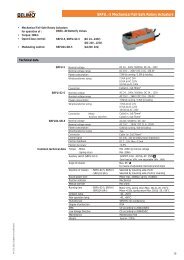
<strong>Technical</strong> <strong>data</strong> <strong>sheet</strong><br />
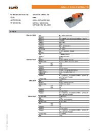
<strong>NV24A</strong>-<strong>MP</strong>-<strong>TPC</strong><br />
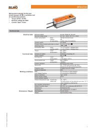
Communication-capable globe valve<br />
actuator for 2-way and 3-way globe<br />
valves<br />
• Actuating force 1000 N<br />
• Nominal voltage AC/DC 24 V<br />
• Control modulating DC (0)<br />
0.5 V...10 V, variable<br />
• Nominal stroke 20 mm<br />
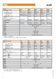
<strong>Technical</strong> <strong>data</strong><br />
Electrical <strong>data</strong> Nominal voltage AC/DC 24 V<br />
Nominal voltage frequency<br />
50/60 Hz<br />
Nominal voltage range<br />
AC 19.2...28.8 V / DC 21.6...28.8 V<br />
Power consumption in operation 3 W<br />
Power consumption in rest position 1.5 W<br />
Power consumption for wire sizing 4.5 VA<br />
Connection supply / control<br />
Terminals 4 mm² and cable 1 m, 4 x 0.75 mm²<br />
Parallel operation<br />
Yes<br />
Functional <strong>data</strong> Actuating force 1000 N<br />
Positioning signal Y<br />
DC 0...10 V<br />
Positioning signal Y note<br />
Input impedance 100 kΩ<br />
Operating range Y<br />
DC 0.5...10 V<br />
Operating range Y variable<br />
Start point DC 0.5 ... 30V<br />
End point DC 2.5 ... 32V<br />
Position feedback U<br />
DC 0.5...10 V<br />
Position feedback U note<br />
max. 0.5 mA<br />
Position feedback U variable<br />
Start point DC 0.5 ... 8V<br />
End point DC 2.5 ... 10V<br />
Position accuracy<br />
5% absolute<br />
Manual override<br />
Gear disengagement with push-button, can be<br />
locked<br />
Nominal stroke<br />
20 mm<br />
Actuating time<br />
150 s / 20 mm<br />
Override control MAX (maximum 100 %<br />
position)<br />
Override control MIN (minimum position) 0 %<br />
Override control ZS (intermediate 50 %<br />
position, only AC)<br />
Override control ZS variable<br />
ZS = MIN ... MAX<br />
Sound power level motor max.<br />
45 dB (A)<br />
Sound power level motor note<br />
55 dB (A) @ 90 s running time<br />
Position indication<br />
Mechanical 5 … 20 mm stroke<br />
Safety Protection class IEC/EN III Safety extra-low voltage<br />
Degree of protection IEC/EN<br />
IP54<br />
EMC<br />
CE in accordance with 2004/108/EC<br />
Certification IEC/EN<br />
Certified to: IEC/EN 60730-1 and IEC/EN<br />
60730-2-14<br />
Mode of operation Type 1<br />
Rated impulse voltage supply / control 0.8 kV<br />
Control pollution degree 3<br />
Ambient temperature 0°C ... 50°C<br />
Non-operating temperature -40°C ... 80°C<br />
Ambient humidity<br />
95% r.h., non-condensing<br />
Maintenance<br />
Maintenance-free<br />
Weight Weight approx. 1.360 kg<br />
www.belimo.com <strong>NV24A</strong>-<strong>MP</strong>-<strong>TPC</strong> • en-gb • 2012-12-12 • Subject to modification 1
<strong>NV24A</strong>-<strong>MP</strong>-<strong>TPC</strong><br />
Safety notes<br />
!<br />
Globe valve actuator, communicative, modulating, AC/<br />
DC 24 V, 1000 N<br />
• This actuator has been designed for application in stationary heating, ventilation and<br />
air-conditioning systems and is not allowed to be used outside the specified field of<br />
application, especially in aircraft or in any other airborne means of transport.<br />
• Only authorised specialists may carry out installation. All applicable legal or<br />
institutional installation regulations must be complied with during installation.<br />
• The switch for changing the direction of motion/the closing point may be adjusted<br />
only by authorised personnel. The direction of stroke is critical, particularly in<br />
connection with frost protection circuits.<br />
• The device may only be opened at the manufacturer's site. It does not contain any<br />
parts that can be replaced or repaired by the user.<br />
• The device contains electrical and electronic components and is not allowed to be<br />
disposed of as household refuse. All locally valid regulations and requirements must<br />
be observed.<br />
Product features<br />
Principle of operation<br />
Adjustable-parameter actuators<br />
Direct mounting<br />
Manual override<br />
High functional reliability<br />
Combination valve/actuator<br />
Position indication<br />
Home position<br />
Direction of stroke switch<br />
Adaption of stroke range<br />
The actuator is connected with a standard modulating signal of DC 0 ... 10V and<br />
travels to the position defined by the positioning signal. The measuring voltage U<br />
serves for the electrical display of the actuator position 0 ... 100% and as slave control<br />
signal for other actuators.<br />
The factory settings cover the most common applications. Input and output signals<br />
and other parameters can be altered with the PC-Tool MFT-P or with the service tool<br />
ZTH-GEN.<br />
Simple direct mounting on the globe valve by means of form-fit hollow clamping jaws.<br />
The actuator can be rotated by 360° on the valve neck.<br />
Manual override with push-button possible - temporary, permanently. The gear is<br />
disengaged and the actuator decoupled for as long as the button is pressed / latched.<br />
The stroke can be adjusted by using a hexagon socket screw key (4 mm), which<br />
is inserted into the top of the actuator. The stroke spindle extends when the key is<br />
rotated clockwise.<br />
The actuator is overload protected, requires no limit switches and automatically stops<br />
when the end stop is reached.<br />
Refer to the valve documentation for suitable valves, their permitted medium<br />
temperatures and closing pressures.<br />
The stroke is indicated mechanically on the bracket with tabs. The stroke range<br />
adjusts itself automatically during operation.<br />
Setting ex-works: Actuator spindle is retracted.<br />
When valve-actuator combinations are shipped, the direction of motion is set in<br />
accordance with the closing point of the valve.<br />
When actuated, the direction of stroke switch changes the running direction in normal<br />
operation.<br />
The first time the supply voltage is switched on, i.e. at the time of commissioning, the<br />
actuator carries out a stroke adaption, which is when the operating range and position<br />
feedback adjust themselves to the mechanical stroke.<br />
Manual triggering of the adaption can be carried out by pressing the "Adaption" button<br />
or with the PC-Tool.<br />
The actuator then moves into the position defined by the positioning signal.<br />
Accessories<br />
Description<br />
Type<br />
Electrical accessories Auxiliary switch add-on, 2 x SPDT S2A-H<br />
Service tools Manual parameterizing device, for MF/<strong>MP</strong>/Modbus/LonWorks actuators ZTH-GEN<br />
and VAV-Control<br />
<strong>Belimo</strong> PC-Tool, software for adjustments and diagnostics<br />
MFT-P<br />
2<br />
<strong>NV24A</strong>-<strong>MP</strong>-<strong>TPC</strong> • en-gb • 2012-12-12 • Subject to modification<br />
www.belimo.com
<strong>NV24A</strong>-<strong>MP</strong>-<strong>TPC</strong><br />
Globe valve actuator, communicative, modulating, AC/<br />
DC 24 V, 1000 N<br />
Electrical installation<br />
!<br />
Notes<br />
• Connection via safety isolating transformer.<br />
• Parallel connection of other actuators possible.<br />
• Direction of stroke switch factory setting: Actuator spindle retracted.<br />
Wiring diagrams<br />
AC/DC 24V, modulating<br />
Operation on the <strong>MP</strong> bus<br />
T<br />
–<br />
~<br />
+<br />
T<br />
~<br />
– +<br />
Y<br />
U<br />
DC (0)0.5... 10 V<br />
DC (0)0.5... 10 V<br />
Y<br />
U<br />
Sensor<br />
<strong>MP</strong><br />
1 2 3 5<br />
Cable colours:<br />
1 = black<br />
2 = red<br />
3 = white<br />
5 = orange<br />
1 2 3 5<br />
Cable colours:<br />
1 = black<br />
2 = red<br />
3 = white<br />
5 = orange<br />
Functions<br />
Functions with basic values<br />
Override control with AC 24V with relay contacts<br />
Override control with AC 24V with rotary<br />
switch<br />
~ T<br />
~ T<br />
Y (DC 0 ... 10 V)<br />
c<br />
Y (DC 0 ... 10 V)<br />
a<br />
b<br />
1<br />
2<br />
3<br />
4<br />
e.g. 1N 4007<br />
e.g. 1N 4007<br />
a b c<br />
Pos<br />
0%<br />
1 0%<br />
1 2 3 5<br />
ZS 50%<br />
1 2 3 5<br />
2 ZS 50%<br />
Y<br />
U<br />
100%<br />
Y<br />
Y<br />
U<br />
3 100%<br />
4 Y<br />
Remote control 0 ... 100%<br />
Follow-up control (position-dependent)<br />
~ T<br />
Y<br />
1 2 3<br />
T<br />
~<br />
Z<br />
4<br />
SGA24<br />
SGF24<br />
SGE24<br />
T<br />
–<br />
~<br />
+<br />
U DC 0.5...10 V<br />
U DC 0.5...10 V<br />
1 2 3 5<br />
1 2 3 5 1 2 3 5<br />
Y<br />
U<br />
Y<br />
U<br />
Y<br />
U<br />
www.belimo.com <strong>NV24A</strong>-<strong>MP</strong>-<strong>TPC</strong> • en-gb • 2012-12-12 • Subject to modification 3
<strong>NV24A</strong>-<strong>MP</strong>-<strong>TPC</strong><br />
Globe valve actuator, communicative, modulating, AC/<br />
DC 24 V, 1000 N<br />
Functions<br />
Control with 4 ... 20 mA via external resistor<br />
T<br />
–<br />
~<br />
+<br />
500 Ω<br />
(–)<br />
(+)<br />
4 ... 20 mA<br />
U<br />
DC 2 ... 10 V<br />
1 2 3 5<br />
Y<br />
U<br />
The 500 Ω resistor converts the<br />
4 ... 20 mA current signal to a<br />
voltage signal DC 2 ... 10 V<br />
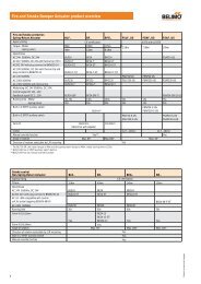
Functions for actuators with specific parameters<br />
Override control and limiting with AC 24V with relay contacts<br />
T<br />
~<br />
e<br />
Y (DC 0 ... 10 V)<br />
a b c d<br />
e.g. 1N 4007<br />
OFF 1)<br />
a b c d e<br />
MIN<br />
1 2 3<br />
5<br />
ZS<br />
MAX<br />
T<br />
~<br />
Y<br />
U<br />
ON<br />
Y<br />
Override control and limiting with AC 24V with rotary switch<br />
T<br />
~<br />
OFF 1)<br />
MIN<br />
ZS<br />
MAX<br />
ON<br />
Y (DC 0 ... 10 V)<br />
e.g. 1N 4007<br />
1 2 3<br />
T<br />
~<br />
Y<br />
5<br />
U<br />
1) Caution: This function is<br />
guaranteed only if the start point<br />
of the operating range is defined<br />
as min. 0.6V.<br />
4<br />
<strong>NV24A</strong>-<strong>MP</strong>-<strong>TPC</strong> • en-gb • 2012-12-12 • Subject to modification<br />
www.belimo.com
<strong>NV24A</strong>-<strong>MP</strong>-<strong>TPC</strong><br />
Globe valve actuator, communicative, modulating, AC/<br />
DC 24 V, 1000 N<br />
Functions<br />
AC 24V; 3-point<br />
~<br />
T<br />
a<br />
b<br />
e.g. 1N 4007<br />
U<br />
3<br />
a<br />
5<br />
b<br />
1 2 3<br />
5<br />
–– ––<br />
Functions when operated on <strong>MP</strong> bus<br />
Connection on the <strong>MP</strong> bus<br />
Power topology<br />
T<br />
–<br />
~<br />
+<br />
<strong>MP</strong><br />
1 2 3 5<br />
Y<br />
U<br />
Supply and communication in<br />
one and the same 3-wire cable<br />
• no shielding or twisting required<br />
• no terminating resister required<br />
There are no restrictions for the<br />
network topology (star, ring, tree<br />
or mixed forms are permitted).<br />
Connection of active sensors<br />
Connection of external switching contact<br />
T<br />
–<br />
~<br />
+<br />
<strong>MP</strong><br />
T<br />
–<br />
~<br />
+<br />
<strong>MP</strong><br />
p<br />
1 2 3 5<br />
1 2 3 5<br />
Y<br />
U<br />
• Supply AC/DC 24 A<br />
• Output signal DC 0 ... 10V<br />
(max. DC 0 ... 32V)<br />
• Resolution 30 mV<br />
Y<br />
U<br />
• Switching current 16 mA @ 24V<br />
• Start point of the operating<br />
range must be parameterised on<br />
the <strong>MP</strong> actuator as ≥ 0.6V<br />
Connection of passive sensors<br />
T<br />
–<br />
~<br />
+<br />
<strong>MP</strong><br />
1 2 3 5<br />
Y<br />
U<br />
Ni1000<br />
PT1000<br />
NTC<br />
–28 ... +98°C 850 ... 1600 Ω 2)<br />
–35 ... +155°C 850 ... 1600 Ω 2)<br />
–10 ... +160°C 1) 200 Ω ... 50 kΩ 2) 1) Depending on the type<br />
2) Resolution 1 Ohm<br />
www.belimo.com <strong>NV24A</strong>-<strong>MP</strong>-<strong>TPC</strong> • en-gb • 2012-12-12 • Subject to modification 5
<strong>NV24A</strong>-<strong>MP</strong>-<strong>TPC</strong><br />
Globe valve actuator, communicative, modulating, AC/<br />
DC 24 V, 1000 N<br />
Indicators and operating controls<br />
4<br />
10<br />
1<br />
2<br />
Adaption<br />
Power<br />
Adress<br />
Status<br />
5<br />
3<br />
(1) Direction of stroke switch<br />
Switching: Direction of stroke changes<br />
(2) Push-button and LED display green<br />
Off: No power supply or malfunction<br />
Illuminated in green: In operation<br />
Press button: Triggers stroke adaption, followed by standard mode<br />
(3) Push-button and LED display yellow<br />
Off: Standard mode<br />
Flickering: <strong>MP</strong> communication active<br />
Illuminated: Adaption procedure active<br />
Blinking: Request for addressing from <strong>MP</strong> master<br />
Press button: Confirmation of addressing<br />
(4) Gear disengagement button<br />
Press button: Gear disengages, motor stops, manual override possible<br />
Release button: Gear engages, standard mode<br />
(5) Service plug<br />
For connecting the parameterisation and service tools<br />
(10) Manual override<br />
Clockwise: Actuator spindle extends<br />
Counterclockwise: Actuator spindle retracts<br />
LED displays (2, green) and (3, yellow)<br />
green: Off; yellow: Illuminated;<br />
Check the supply connections. The phases may have been switched.<br />
Dimensions [mm]<br />
Dimensional drawings<br />
215<br />
45<br />
98<br />
160<br />
150<br />
Further documentation<br />
• Data <strong>sheet</strong>s for globe valves<br />
• Installation instructions for actuators and/or globe valves, respectively<br />
• Notes for project planning, 2-way and 3-way globe valves<br />
• Overview "Valve-actuator combinations"<br />
6<br />
<strong>NV24A</strong>-<strong>MP</strong>-<strong>TPC</strong> • en-gb • 2012-12-12 • Subject to modification<br />
www.belimo.com
LV..A(-..) / NV..A(-..) / SV..A(-..)<br />
71398-00001.A<br />
1<br />
A<br />
AB<br />
A<br />
AB<br />
B<br />
A<br />
AB<br />
2<br />
3<br />
1<br />
4mm<br />
2<br />
1<br />
2<br />
2<br />
5Nm 4mm<br />
4<br />
2<br />
1<br />
1<br />
2<br />
www.belimo.com M6-LV..A(-..)/NV..A(-..)/SV..A(-..) • v1.0 • 07.2012 / 2
LV..A(-..) / NV..A(-..) / SV..A(-..)<br />
AC 24 V / DC 24 V<br />
T<br />
~<br />
– +<br />
AC 230 V N L<br />
!<br />
1 2 3<br />
1 2 3<br />
a<br />
b<br />
a<br />
b<br />
a<br />
b<br />
a<br />
b<br />
LV(C)24A<br />
NV(C)24A<br />
SV(C)24A<br />
LV(C)230A<br />
NV(C)230A<br />
SV(C)230A<br />
AC 24 V / DC 24 V<br />
T<br />
~<br />
– +<br />
AC 230 V<br />
!<br />
N<br />
L<br />
0<br />
0<br />
1 2 3<br />
1 2 3<br />
a<br />
b<br />
a<br />
b<br />
a<br />
b<br />
a<br />
b<br />
a<br />
b<br />
a<br />
b<br />
LV(C)24A<br />
NV(C)24A<br />
SV(C)24A<br />
LV(C)230A<br />
NV(C)230A<br />
SV(C)230A<br />
AC 24 V / DC 24 V<br />
T<br />
–<br />
~<br />
+<br />
T<br />
–<br />
~<br />
+<br />
Y<br />
U<br />
DC (0) 0.5 ... 10 V<br />
DC (0) 0.5 ... 10 V<br />
Y<br />
U<br />
DC (0) 2 ... 10 V<br />
DC (0) 2 ... 10 V<br />
1 2 3 5<br />
1 2 3 5<br />
LV(C)24A-SZ<br />
NV(C)24A-SZ<br />
SV(C)24A-SZ<br />
LV(C)24A-MF<br />
NV(C)24A-MF<br />
SV(C)24A-MF<br />
LV(C)24A-SR<br />
NV(C)24A-SR<br />
SV(C)24A-SR<br />
T<br />
–<br />
~<br />
+<br />
Y<br />
U<br />
DC (0) 0.5 ... 10 V<br />
<strong>MP</strong><br />
1 2 3 5<br />
LV(C)24A-<strong>MP</strong><br />
NV(C)24A-<strong>MP</strong><br />
SV(C)24A-<strong>MP</strong><br />
/ 2 M6-LV..A(-..)/NV..A(-..)/SV..A(-..) • v1.0 • 07.2012 www.belimo.com
![SV24A-SZ-TPC_datasheet_en[2013.03.26].pdf - Belimo Actuators ...](https://img.yumpu.com/49758098/1/184x260/sv24a-sz-tpc-datasheet-en20130326pdf-belimo-actuators-.jpg?quality=85)

![CCV_V7[2013.07.16].pdf - Belimo Actuators (Shanghai)](https://img.yumpu.com/46161653/1/184x260/ccv-v720130716pdf-belimo-actuators-shanghai.jpg?quality=85)