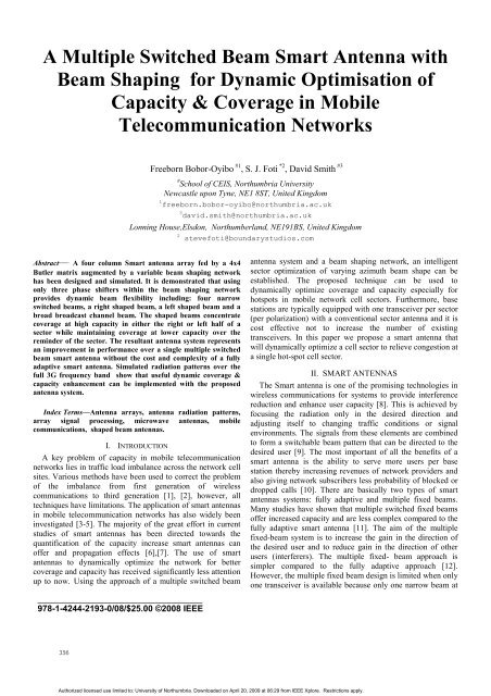
A multiple switched beam smart antenna with beam shaping for ...
A multiple switched beam smart antenna with beam shaping for ...
A multiple switched beam smart antenna with beam shaping for ...
You also want an ePaper? Increase the reach of your titles
YUMPU automatically turns print PDFs into web optimized ePapers that Google loves.
A Multiple Switched Beam Smart Antenna <strong>with</strong><br />
Beam Shaping <strong>for</strong> Dynamic Optimisation of<br />
Capacity & Coverage in Mobile<br />
Telecommunication Networks<br />
Freeborn Bobor-Oyibo #1 , S. J. Foti *2 , David Smith #3<br />
# School of CEIS, Northumbria University<br />
Newcastle upon Tyne, NE1 8ST, United Kingdom<br />
1 freeborn.bobor-oyibo@northumbria.ac.uk<br />
3 david.smith@northumbria.ac.uk<br />
Lonning House,Elsdon, Northumberland, NE191BS, United Kingdom<br />
2 stevefoti@boundarystudios.com<br />
Abstract— A four column Smart <strong>antenna</strong> array fed by a 4x4<br />
Butler matrix augmented by a variable <strong>beam</strong> <strong>shaping</strong> network<br />
has been designed and simulated. It is demonstrated that using<br />
only three phase shifters <strong>with</strong>in the <strong>beam</strong> <strong>shaping</strong> network<br />
provides dynamic <strong>beam</strong> flexibility including: four narrow<br />
<strong>switched</strong> <strong>beam</strong>s, a right shaped <strong>beam</strong>, a left shaped <strong>beam</strong> and a<br />
broad broadcast channel <strong>beam</strong>. The shaped <strong>beam</strong>s concentrate<br />
coverage at high capacity in either the right or left half of a<br />
sector while maintaining coverage at lower capacity over the<br />
reminder of the sector. The resultant <strong>antenna</strong> system represents<br />
an improvement in per<strong>for</strong>mance over a single <strong>multiple</strong> <strong>switched</strong><br />
<strong>beam</strong> <strong>smart</strong> <strong>antenna</strong> <strong>with</strong>out the cost and complexity of a fully<br />
adaptive <strong>smart</strong> <strong>antenna</strong>. Simulated radiation patterns over the<br />
full 3G frequency band show that useful dynamic coverage &<br />
capacity enhancement can be implemented <strong>with</strong> the proposed<br />
<strong>antenna</strong> system.<br />
Index Terms—Antenna arrays, <strong>antenna</strong> radiation patterns,<br />
array signal processing, microwave <strong>antenna</strong>s, mobile<br />
communications, shaped <strong>beam</strong> <strong>antenna</strong>s.<br />
I. INTRODUCTION<br />
A key problem of capacity in mobile telecommunication<br />
networks lies in traffic load imbalance across the network cell<br />
sites. Various methods have been used to correct the problem<br />
of the imbalance from first generation of wireless<br />
communications to third generation [1], [2], however, all<br />
techniques have limitations. The application of <strong>smart</strong> <strong>antenna</strong>s<br />
in mobile telecommunication networks has also widely been<br />
investigated [3-5]. The majority of the great ef<strong>for</strong>t in current<br />
studies of <strong>smart</strong> <strong>antenna</strong>s has been directed towards the<br />
quantification of the capacity increase <strong>smart</strong> <strong>antenna</strong>s can<br />
offer and propagation effects [6],[7]. The use of <strong>smart</strong><br />
<strong>antenna</strong>s to dynamically optimize the network <strong>for</strong> better<br />
coverage and capacity has received significantly less attention<br />
up to now. Using the approach of a <strong>multiple</strong> <strong>switched</strong> <strong>beam</strong><br />
______________________________________<br />
978-1-4244-2193-0/08/$25.00 ©2008 IEEE<br />
<strong>antenna</strong> system and a <strong>beam</strong> <strong>shaping</strong> network, an intelligent<br />
sector optimization of varying azimuth <strong>beam</strong> shape can be<br />
established. The proposed technique can be used to<br />
dynamically optimize coverage and capacity especially <strong>for</strong><br />
hotspots in mobile network cell sectors. Furthermore, base<br />
stations are typically equipped <strong>with</strong> one transceiver per sector<br />
(per polarization) <strong>with</strong> a conventional sector <strong>antenna</strong> and it is<br />
cost effective not to increase the number of existing<br />
transceivers. In this paper we propose a <strong>smart</strong> <strong>antenna</strong> that<br />
will dynamically optimize a cell sector to relieve congestion at<br />
a single hot-spot cell sector.<br />
II. SMART ANTENNAS<br />
The Smart <strong>antenna</strong> is one of the promising technologies in<br />
wireless communications <strong>for</strong> systems to provide interference<br />
reduction and enhance user capacity [8]. This is achieved by<br />
focusing the radiation only in the desired direction and<br />
adjusting itself to changing traffic conditions or signal<br />
environments. The signals from these elements are combined<br />
to <strong>for</strong>m a switchable <strong>beam</strong> pattern that can be directed to the<br />
desired user [9]. The most important of all the benefits of a<br />
<strong>smart</strong> <strong>antenna</strong> is the ability to serve more users per base<br />
station thereby increasing revenues of network providers and<br />
also giving network subscribers less probability of blocked or<br />
dropped calls [10]. There are basically two types of <strong>smart</strong><br />
<strong>antenna</strong>s systems: fully adaptive and <strong>multiple</strong> fixed <strong>beam</strong>s.<br />
Many studies have shown that <strong>multiple</strong> <strong>switched</strong> fixed <strong>beam</strong>s<br />
offer increased capacity and are less complex compared to the<br />
fully adaptive <strong>smart</strong> <strong>antenna</strong> [11]. The aim of the <strong>multiple</strong><br />
fixed-<strong>beam</strong> system is to increase the gain in the direction of<br />
the desired user and to reduce gain in the direction of other<br />
users (interferers). The <strong>multiple</strong> fixed- <strong>beam</strong> approach is<br />
simpler compared to the fully adaptive approach [12].<br />
However, the <strong>multiple</strong> fixed <strong>beam</strong> design is limited when only<br />
one transceiver is available because only one narrow <strong>beam</strong> at<br />
<br />
Authorized licensed use limited to: University of Northumbria. Downloaded on April 20, 2009 at 06:29 from IEEE Xplore. Restrictions apply.
a time can be used. The block diagram of the proposed <strong>smart</strong><br />
<strong>antenna</strong> system is shown in figure 1. The fundamental<br />
components of the system are: the <strong>antenna</strong> array, <strong>multiple</strong><br />
<strong>beam</strong> <strong>for</strong>ming network (4x4 Butler Matrix) and the <strong>beam</strong><br />
<strong>shaping</strong> network. Each of the array columns has a gain of<br />
17.5dBi. The horizontal <strong>beam</strong> shape produced by the <strong>antenna</strong><br />
array is dependent upon the complex weights (magnitude and<br />
phase) applied to each array column. The complex weights are<br />
provided by the array feed network. The total feed network is<br />
realised by cascading a 4x4 Butler matrix <strong>beam</strong> <strong>for</strong>ming<br />
network and a <strong>beam</strong> <strong>shaping</strong> network. The <strong>for</strong>mer produces<br />
<strong>multiple</strong> narrow <strong>beam</strong>s each corresponding to a signal at one<br />
of the four <strong>beam</strong> ports and latter provides a combination of<br />
excitation (i.e. ‘‘<strong>beam</strong> blending’’) to each of the <strong>beam</strong> ports.<br />
The 4x4 Butler Matrix produces equal amplitudes and linear<br />
phase progressions to the array elements and the <strong>beam</strong><br />
<strong>shaping</strong> network provides simultaneous excitation of the <strong>beam</strong><br />
ports <strong>with</strong> relative amplitudes and phase. The relative<br />
amplitudes are dynamically changed by adjusting the three<br />
phase shifters <strong>with</strong>in the <strong>beam</strong> <strong>shaping</strong> network, (BSN). This<br />
results in the required complex weights at the array elements.<br />
It is a <strong>beam</strong> <strong>for</strong>ming network that uses a combination of 90°<br />
hybrids and fixed transmission line phase shifters to <strong>for</strong>m N<br />
simultaneous independent <strong>beam</strong>s from an N element <strong>antenna</strong><br />
array. It per<strong>for</strong>ms a spatial discrete Fourier trans<strong>for</strong>m and<br />
provides overlapping orthogonal <strong>beam</strong>s. When used <strong>with</strong> a<br />
linear array the Butler matrix produces <strong>beam</strong>s that overlap at<br />
3.9 dB below the <strong>beam</strong> maximum. A Butler matrix-fed array<br />
can provide <strong>beam</strong>s that can be used by a dedicated transmitter<br />
and/or receiver, or a single transmitter and/or receiver can be<br />
used and the appropriate <strong>beam</strong> can be selected using an RF<br />
switch. Any signal input into one of the butler matrix input<br />
ports will be divided equally among the output ports <strong>with</strong> a<br />
progressive phase delay. The passive Butler matrix will be<br />
dynamically controlled by the <strong>beam</strong> <strong>shaping</strong> network.<br />
Depending upon the communications traffic demand, a control<br />
algorithm can adjust the relative power divider/combiner ratio<br />
to blend all the <strong>beam</strong>s, or do <strong>beam</strong> switching or <strong>beam</strong><br />
broading <strong>for</strong> optimum service.<br />
B. Beam Shaping Network<br />
X<br />
X<br />
X<br />
X<br />
X<br />
X<br />
X<br />
X<br />
The <strong>beam</strong> <strong>shaping</strong> network is essentially a variable 4-way<br />
power divider/combiner that utilizes a 2-way variable power<br />
divider/combiner which drives two 2-way variable power<br />
dividers/combiners as shown in Figure 2.1. Each 2-way<br />
variable power divider/combiner is realised as shown in the<br />
network of figure 2.2.<br />
D D D D<br />
2 nd Feed<br />
Network<br />
To/From Butler Matrix Beam Ports<br />
Uplink<br />
Butler<br />
Downlink<br />
Butler<br />
Q<br />
Q<br />
Uplink<br />
BSN<br />
Downlink<br />
BSN<br />
Dipl<br />
Q<br />
Q<br />
Tran<br />
Figure 1 Smart Antenna system <strong>with</strong> <strong>beam</strong> <strong>shaping</strong><br />
Q<br />
III. BEAM FORMING AND BEAM SHAPING NETWORKS<br />
Q<br />
A. Beam Forming Network<br />
The Butler matrix has been chosen <strong>for</strong> this design because it is<br />
simple to realize compared to other <strong>beam</strong>-<strong>for</strong>ming networks.<br />
Input<br />
Figure 2.1 Beam Shaping Network<br />
<br />
Authorized licensed use limited to: University of Northumbria. Downloaded on April 20, 2009 at 06:29 from IEEE Xplore. Restrictions apply.
n order to adapt to an unequal user distribution between <strong>beam</strong>s<br />
it is of a great advantage to share the power that is available to<br />
serve a sector dynamically between the <strong>beam</strong>s of the sector<br />
providing more power to areas that have more users. The<br />
advantage of this dynamic sharing is to reduce dropped calls<br />
in a sector. The angular <strong>beam</strong> width of the sector <strong>smart</strong><br />
<strong>antenna</strong> can be dynamically shaped to the right or left hand of<br />
the sector to accommodate the traffic of the sector. The<br />
proposed <strong>smart</strong> <strong>antenna</strong> has three shaped <strong>beam</strong>s. They are the<br />
right-hand shaped <strong>beam</strong>, left-hand shaped <strong>beam</strong> and a broad<br />
shaped <strong>beam</strong> <strong>for</strong> the broadcast channel to avoid the use of<br />
separate integrated sector <strong>antenna</strong> <strong>for</strong> the broadcast channel.<br />
These are in addition to the four narrow overlapping <strong>beam</strong>s.<br />
3G systems need constant monitoring and continuous<br />
optimization <strong>for</strong> coverage and capacity because of the<br />
subscriber locations in the sector and traffic behaviour. The<br />
behaviour of the traffic demand affects the network quality of<br />
the mobile network provider [13]. To avoid coverage holes<br />
cell overlaps have been used as a remedy, but waste power<br />
when the traffic demand moves to another sector. In order to<br />
adapt to an unequal user distribution between <strong>beam</strong>s it is of a<br />
great advantage to share the power that is available to serve a<br />
sector dynamically between the <strong>beam</strong>s of the sector providing<br />
more power to areas that have more users. The advantage of<br />
this dynamic sharing is to reduce dropped calls in a sector.<br />
The angular <strong>beam</strong> width of the sector <strong>smart</strong> <strong>antenna</strong> can be<br />
dynamically shaped to the right or left hand of the sector to<br />
accommodate the traffic of the sector. The proposed <strong>smart</strong><br />
<strong>antenna</strong> has three shaped <strong>beam</strong>s, right-hand shaped <strong>beam</strong>, lefthand<br />
shaped <strong>beam</strong> and a broad shaped <strong>beam</strong> <strong>for</strong> the broadcast<br />
channel to avoid the use of separate integrated sector <strong>antenna</strong><br />
<strong>for</strong> the broadcast channel. These are in addition to the four<br />
narrow overlapping <strong>beam</strong>s.<br />
Q<br />
I<br />
IV. SIMULATION RESULTS<br />
C. Multiple Narrow Beams<br />
The per<strong>for</strong>mance of the proposed <strong>smart</strong> <strong>antenna</strong> over the<br />
uplink and downlink bands <strong>for</strong> a specific UK 3G network<br />
operator (Orange, UK), ( downlink , = 2.1597GHz,<br />
2.1647GHz, and 2.1697GHz and uplink =<br />
1.9697GHz, 1.9747GHz and 1.9797GHz ) has been simulated<br />
<strong>for</strong> <strong>multiple</strong> narrow <strong>beam</strong>s as shown in Figure 3 and Figure 4.<br />
It was found that the <strong>beam</strong>s are virtually invariant over each<br />
of the bands based upon the ideal network model and the<br />
narrow uplink and downlink bands.<br />
Figure 3 Downlink Multiple Narrow <strong>beam</strong>s @<br />
=2.165GHz<br />
D. Steered Beams<br />
In addition to generating <strong>multiple</strong> narrow <strong>beam</strong>s this<br />
arrangement is also able to generate shaped <strong>beam</strong>s through a<br />
simple variation of the complex weightings. Figure 5 and<br />
figure 6 present the right, left and broad shaped <strong>beam</strong>s <strong>for</strong> the<br />
uplink and downlink <strong>for</strong> this <strong>antenna</strong>. Again it has been found<br />
these <strong>beam</strong> shapes are virtually frequency invariant over their<br />
respective bands based over the uplink and downlink bands.<br />
-<br />
Q<br />
Input<br />
Figure 2.2. 2-way variable power divider/combiner controlled<br />
by one phase shifter<br />
Figure 4 Uplink Multiple Narrow <strong>beam</strong>s @<br />
=1.975GHz<br />
<br />
Authorized licensed use limited to: University of Northumbria. Downloaded on April 20, 2009 at 06:29 from IEEE Xplore. Restrictions apply.
Figure 6. Uplink Shaped <strong>beam</strong>s @<br />
=1.975GHz<br />
Figure 5. Downlink Shaped <strong>beam</strong>s @<br />
=2.165GHz<br />
V. CONCLUSIONS<br />
This research has explored the importance of using <strong>smart</strong><br />
<strong>antenna</strong> systems <strong>for</strong> traffic load balancing especially in<br />
hotspots of wireless networks. We have successfully designed,<br />
simulated and analysed a <strong>multiple</strong> <strong>switched</strong> <strong>beam</strong> <strong>smart</strong><br />
<strong>antenna</strong> <strong>with</strong> <strong>beam</strong> <strong>shaping</strong> augmentation <strong>for</strong> dynamic<br />
optimization of capacity and coverage <strong>for</strong> the up and<br />
downlinks of 3G mobile telecommunication networks. Future<br />
work to aid network planners could employ this Smart<br />
Antenna System computer model coupled <strong>with</strong> a suitable<br />
propagation model and terrain map to predict “<strong>beam</strong><br />
footprint” contour plots <strong>for</strong> specific geographical regions.<br />
[7] K. I. Pedersen, P. E. Mogensen, and J. R. Moreno, “Application and<br />
per<strong>for</strong>mance of downlink <strong>beam</strong><strong>for</strong>ming techniques in UMTS,” IEEE<br />
Commun. Mag., pp. 134–143, Oct. 2003.<br />
[8] R.H. Roy, ‘An overview of <strong>smart</strong> Antenna technology: the Next Wave<br />
in Wireless Communication,’ 1998 IEEE Aerospace Conference, Vol.3<br />
pp. 339-345, May 1998<br />
[9] W. L. Stutzman and G. A. Thiele (1981), ’Antenna theory and Design’,<br />
John Wiley & Sons, New York.<br />
[10] J. Litva and T. K.-Y. Lo (1996), Digital Beam<strong>for</strong>ming in Wireless<br />
Communications, Artech House, Boston.<br />
[11] C A. Osseiran et al., ‘Downlink capacity comparison between different<br />
<strong>smart</strong> <strong>antenna</strong> concepts in a mixed service WCDMA system,’ in proc.<br />
IEEE Veh. Technol. Conf. Fall, Atlantic City NJ, 2001, vol. 3, pp.<br />
1528-1532.<br />
[12] J. C. Liberti, Jr., and T.S. Rappaport, (1999), Smart Antennas <strong>for</strong><br />
wireless communications: IS-95 and Third Generation CDMA<br />
Applications, Prentice Hall PTR, Upper Saddle River, NJ.<br />
[13] J. Laiho, A. Wacker and T. Novosad ’Radio Network Planning and<br />
Optimisation <strong>for</strong> UMTS second Edition, John Wiley & Sons Ltd 2006.<br />
REFERENCES<br />
[1] T. Yum and W. Wong, Hot-spot traffic relief in cellular systems, IEEE<br />
Journal on Selected Areas in Communications, vol. 11, no. 6, pp. 934-<br />
940, August 1993.<br />
[2] Y. Argyropoulos, . S. Jordan, and S. Kumar, Dynamic channel<br />
allocation in interference-limited cellular systems <strong>with</strong> uneven traffic<br />
distribution, IEEE Transactions on Vehicular Technology, vol. 48, no.<br />
1, pp 224-232, January 1999<br />
[3] C. Lee, H. Kang, and T. Park, “Dynamic sectorization of microcells<br />
<strong>for</strong> balanced traffic in cdma: genetic algorithms approach,” IEEE Trans.<br />
Veh. Technol.<br />
[4] Lehne, P. H, and Pettersen, M. ‘An overview of Smart Antenna<br />
Technology <strong>for</strong> mobile communication systems’ IEEE<br />
communications surveys, vol.2, pp.2-13, 1999.<br />
[5] L. Godara, “Applications of <strong>antenna</strong> arrays to mobile communications,<br />
Part I: Per<strong>for</strong>mance improvement, feasibility, and system<br />
considerations,” Proc. IEEE, vol. 85, pp. 1031–1060, Jul. 1997.<br />
[6] A. Osseiran and A. Logothetis, ‘Smart Antenna in a WCDMA Radio<br />
Network System: Modeling and Evaluations, IEEE transaction on<br />
Antennas and propagation Vol.54,No 11 November, 2006 pp. 3302-<br />
3316<br />
.<br />
<br />
Authorized licensed use limited to: University of Northumbria. Downloaded on April 20, 2009 at 06:29 from IEEE Xplore. Restrictions apply.


