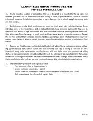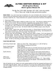
installation instructions for electronic single fire ... - Ultima Products
installation instructions for electronic single fire ... - Ultima Products
installation instructions for electronic single fire ... - Ultima Products

Create successful ePaper yourself
Turn your PDF publications into a flip-book with our unique Google optimized e-Paper software.
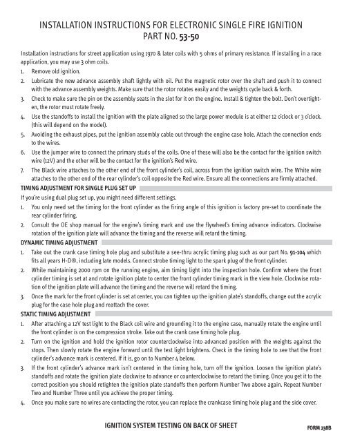
INSTALLATION INSTRUCTIONS FOR ELECTRONIC SINGLE FIRE IGNITION<br />
PART NO. 53-50<br />
Installation <strong>instructions</strong> <strong>for</strong> street application using 1970 & later coils with 5 ohms of primary resistance. If installing in a race<br />
application, you may use 3 ohm coils.<br />
1. Remove old ignition.<br />
2. Lubricate the new advance assembly shaft lightly with oil. Put the magnetic rotor over the shaft and push it to connect<br />
with the advance assembly weights. Make sure that the rotor rotates easily and the weights cycle back & <strong>for</strong>th.<br />
3. Check to make sure the pin on the assembly seats in the slot <strong>for</strong> it on the engine. Install & tighten the bolt. Don’t overtighten,<br />
the rotor must rotate freely.<br />
4. Use the standoffs to install the ignition with the plate aligned so the large power module is at either 12 o’clock or 3 o’clock.<br />
(this will depend on the model).<br />
5. Avoiding the exhaust pipes, put the ignition assembly cable out through the engine case hole. Attach the connection ends<br />
to the wires.<br />
6. Use the jumper wire to connect the primary studs of the coils. One of these will also be the contact <strong>for</strong> the ignition switch<br />
wire (12V) and the other will be the contact <strong>for</strong> the ignition’s Red wire.<br />
7. The Black wire attaches to the other end of the front cylinder’s coil, across from the ignition switch wire. The White wire<br />
attaches to the other end of the rear cylinder’s coil opposite the Red wire. Ensure all the connections are firmly attached.<br />
TIMING ADJUSTMENT FOR SINGLE PLUG SET UP<br />
If you’re using dual plug set up, you might need different settings.<br />
1. You only need set the timing <strong>for</strong> the front cylinder as the firing angle of this ignition is factory pre-set to coordinate the<br />
rear cylinder firing.<br />
2. Consult the OE shop manual <strong>for</strong> the engine’s timing mark and use the flywheel’s timing advance indicators. Clockwise<br />
rotation of the ignition plate will advance the timing and the reverse will retard the timing.<br />
DYNAMIC TIMING ADJUSTMENT<br />
1. Take out the crank case timing hole plug and substitute a see-thru acrylic timing plug such as our part No. 91-104 which<br />
fits all years H-D®, including late models. Connect strobe timing light to the spark plug of the front cylinder.<br />
2. While maintaining 2000 rpm on the running engine, aim timing light into the inspection hole. Confirm where the front<br />
cylinder timing is set at and rotate ignition plate to center the front cylinder timing mark in the view hole. Clockwise rotation<br />
of the ignition plate will advance the timing and the reverse will retard the timing.<br />
3. Once the mark <strong>for</strong> the front cylinder is set at center, you can tighten up the ignition plate’s standoffs, change out the acrylic<br />
plug <strong>for</strong> the case hole plug and reattach the cover.<br />
STATIC TIMING ADJUSTMENT<br />
1. After attaching a 12V test light to the Black coil wire and grounding it to the engine case, manually rotate the engine until<br />
the front cylinder is on the compression stroke. Take out the crank case timing hole plug.<br />
2. Turn on the ignition and hold the ignition rotor counterclockwise into advanced position with the weights against the<br />
stops. Then slowly rotate the engine <strong>for</strong>ward until the test light brightens. Check in the timing hole to see that the front<br />
cylinder’s advance mark is centered. If it is, go on to Number 4 below.<br />
3. If the front cylinder’s advance mark isn’t centered in the timing hole, turn off the ignition. Loosen the ignition plate’s<br />
standoffs and rotate the ignition plate clockwise to advance or counterclockwise to retard the timing. Once you get it to the<br />
correct position you should retighten the ignition plate standoffs then per<strong>for</strong>m Number Two above again. Repeat Number<br />
Two and Number Three until you achieve the proper timing.<br />
4. Once you make sure no wires are contacting the rotor, you can replace the crankcase timing hole plug and the side cover.<br />
IGNITION SYSTEM TESTING ON BACK OF SHEET<br />
FORM 238B
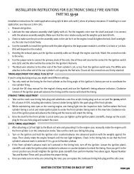
IGNITION SYSTEM TESTING FOR PART NO. 53-50<br />
VISUAL INSPECTION<br />
Check to see that the rotor isn’t rubbing on the power modules on the ignition plate. Fully advance the rotor and it should<br />
snap back to the original position. Do the two above inspections once when the motor is cold and then later when the<br />
engine is hot. After marking the timing on the case and the ignition plate, remove the ignition and make sure that the<br />
advance isn’t contacting the ignition plate. Check the cable <strong>for</strong> damage caused by pinching or heat. Make sure areas of<br />
splicing & crimping are firmly attached. See if the connections <strong>for</strong> the coil are clean & tight. You can install split lock washers<br />
on the coil screws. Take off the spark plug wires and look <strong>for</strong> corrosion and cracked or chipped insulation. Using an<br />
ohmmeter, connect both ends of the wire and tweak and twist to check if the wiring is broken. Pull out the spark plugs and<br />
check <strong>for</strong> fouling. Clean them & reinstall unless too dirty, then just replace them with new ones.<br />
TESTING THE VOLTAGE<br />
There should be a minimum of 3 ohms primary resistance of the engine coils - don’t <strong>for</strong>get to take the resistance of the<br />
meter leads into consideration. If the ohmmeter shows shorting or open primary, you must replace the coils. After pre<strong>for</strong>ming<br />
this test, you can manually rotate the engine until the rotor’s magnet is directed away from the power modules.<br />
Turn the ignition on and then measure the voltage between the ground and the coil (+) terminal. If you get a reading that<br />
is approximately one volt less than the battery voltage this is to be expected because the wiring has its own resistance. If<br />
the voltage is noticeably lower, you can try to find voltage drops which may occur at any splicing, connectors, circuit<br />
breakers, switches or other devices in the wiring that interrupt the power to the coils. IMPORTANT NOTE: Don’t keep the<br />
ignition on longer than 4-5 minutes while doing this test because the coils can overheat and be damaged. Using the ohmmeter,<br />
find out the voltage between each coil (-) terminal and ground. Expect it to be 0.8 to 1.4 volts when the magnet is<br />
directed away from the power modules. Manually rotate the engine so the magnet points at the sensor located behind the<br />
raised line on the front of the module. The voltage should rise to approximately the battery voltage, indication that the<br />
power module is switching and probably working correctly. If the voltage is still low, the gap between the sensor and rotor<br />
may be too large. If the gap between the sensor and rotor is greater than 0.040”, it can be the reason the module doesn’t<br />
switch. The proper gap between these two components is between 0.025” and 0.040”. If the output has a short, this will<br />
also keep the voltage low. If the voltage is consistently high, make sure the mounting plate is firmly grounded and that the<br />
power modules are receiving power. If this checks out, it could mean that the module is not working.<br />
TEST WITH OHMMETER<br />
Disconnect the unit wires from the coils then connect the negative ohmmeter lead to the mounting plate and positive lead<br />
to one of the coil (-) wires. this should give an open reading (infinite ohms) on all ranges. Any other reading than this<br />
indicated you have a damaged output. If the ohmmeter has a diode test, reverse the leads and a diode drop of 0.5 t0 0.6<br />
will be the reading.. NOTE: Many inexpensive ohmmeters reverse the polarity of the leads inside the meter. This causes a<br />
false “bad” reading due to the resistance of the reverse diode as described. Don’t attempt to meter the ohms between any<br />
other points, or with power applied to the module because these readings may not be reliable due to differences in the<br />
meter or component tolerances.<br />
TESTING THE COILS<br />
Remove all wiring from the coils and measure the primary resistance between the screw terminals. Next, measure the<br />
secondary resistance between the high voltage outputs. If you are using <strong>single</strong> output coils, you can measure the resistance<br />
between the high voltage output and either of the screw terminals.<br />
NOTE ON OHMMETERS<br />
If possible, use a good quality ohmmeter that has a low ohms range to measure the primary resistance accurately.<br />
Depending on the quality of the ohmmeter and the leads resistance, the readings will vary somewhat. If the coil is damaged,<br />
it will usually show up with open or shorted leads on the primary or secondary.<br />
SEE YOUR COIL MANUFACTURER FOR RESISTANCE SPECIFICATIONS