DYNA® EVO® & T.C.® MODELS '91 - '05 - Ultima Products
DYNA® EVO® & T.C.® MODELS '91 - '05 - Ultima Products
DYNA® EVO® & T.C.® MODELS '91 - '05 - Ultima Products

You also want an ePaper? Increase the reach of your titles
YUMPU automatically turns print PDFs into web optimized ePapers that Google loves.
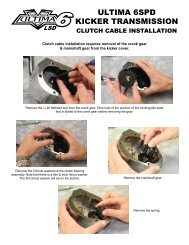
III. INSTALLING PULLEYS AND BELT1.Install the clutch basket assembly onto the transmission mainshaft. Applyred Loctite to the mainshaft nut and torque to 55-65 ft lb.2.Install the stator, rotor, washer and any shims that were present or are needed. <strong>Ultima</strong> Belt Drives are not as sensitive as chaindrives to pulley alignment as the clutch basket acts as a guide but proper alignment should be checked. To insure a completelydry running primary many people use a bead of clear RTV Silicone at each spline to insure no oil will travel between the shaft andspline.Install the belt and front pulley at the same time. It can be tricky to align the splines with some tension on the belt. Once you getthe spline started you can tap the pulley on lightly with a dead blow or plastic hammer.3.Install the motor pulley nut using red Loctite and torque to mfgrecommended specification.
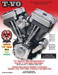
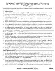
IV. INSTALLING THE CLUTCH COMPONENTS1.<strong>Ultima</strong> 2” belt drives utilize 8 of the old style 900cc sportster steel drive plates and 8 special size fiber platesdesigned to provide a very adjustable clutch package. When installing the clutch pack install the thick .119” steelplate first then alternate fiber/steel. The last plate you install should be fiber.2.Check the pressure plate screws to ensure they are all tight and the heads of the bolts are sitting belowthe plate surface.3.Install the clutch adjusting screw using a small amount of high temp grease or anti-sieze on the threadand on the clutch pushrod end. Don’t get too much grease out there –Remember this is a DRY clutch.
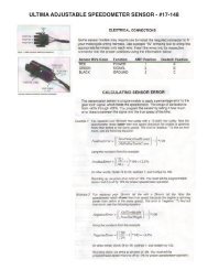
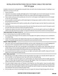
witness marks4.Align the witness marks on the pressure plate and inner clutch hub as shown when installing pressure plate.This will insure clutch hub studs will be centered in the appropriate pressure plate holes.NOTE: CENTER PUSHROD IS REQUIREDThe center clutch push rods (located in the transmission main shaft) mayneed to be changed depending on setup. Below is a list of availble sizes.PART# LENGTH DESCRIPTION96-442 11.375” 1987-1989 5 speed96-538 10.8125” 1990+ 5 speed96-469 11.875” 1985+ 5 & 6 speed5.After installing the pressure plate, install clutch springs w/supplied spring collars and narrow-headed 12-24 bolts.Install using blue Loctite. Spring collars should bottom on clutch hub studs. Torque to 90 in-lbs.In higher horsepower applications, heavier springs are available.Midwest Part#96-251 (68lbs @ 1”)Midwest Part#96-249 (82lbs @ 1”) Midwest Part#96-250 (98lbs @ 1”)
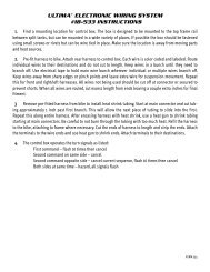
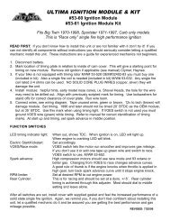
V. INSTALLING THE STARTER GEARStarter Gear Assembly58-718 1/4-20 x 2.75 (89’-93’ supplied)58-719 10-32 x 2.75 (94’-06’ available)Install your starter motor to the motor plate then install the starter drive gear assembly in the order shown using blue Loctite. Thestarter drive gear should be a minimum of .150” from the clutch basket starter ring gear once installed. APPLY SOME HIGH TEMPGREASE OR ANTI-SIEZE TO THE STARTER END CAP BUSHING. Apply upward pressure to end cap when torquing to 18-22ftlbs, always use blue Locktite on end cap bolts. Reapply grease to bushing every 6 months minimum - DO NOT RUN DRY!VI. INSTALLING PULLEY CAP AND CLUTCH TRIM RINGInstall motor pulley cap and clutch basket trim ring at this time using the supplied 1/4-20bolts. Torque to 120-140 in-lbs w/blue Loctite.VII. KICKSTAND CONSIDERATIONSCheck your kickstand clearance to the belt by pushing down on the belt then adding at lease 1/2”.Use MWM # 5-190 adjustable kickstand leg stop if needed. This is an important safety check andshould be performed before initial startup.