Using Supervisory Control And Data Acquisition (SCADA) System in ...
Using Supervisory Control And Data Acquisition (SCADA) System in ...
Using Supervisory Control And Data Acquisition (SCADA) System in ...

Create successful ePaper yourself
Turn your PDF publications into a flip-book with our unique Google optimized e-Paper software.
Tishreen University Journal for Research and Scientific Studies - Eng<strong>in</strong>eer<strong>in</strong>g Sciences Series Vol. ( ) No. ( )<br />
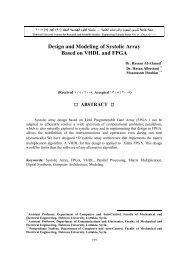
<strong>Us<strong>in</strong>g</strong> <strong>Supervisory</strong> <strong>Control</strong> <strong>And</strong> <strong>Data</strong> <strong>Acquisition</strong> (<strong>SCADA</strong>)<br />
<strong>System</strong> <strong>in</strong> the Management of a Diesel Generator<br />
Dr. Ebraheem Alshami *<br />
Dr. Hassan Albustani **<br />
Mohammed Melhem***<br />
(Received / / . Accepted / / )<br />
ABSTRACT<br />
<strong>Supervisory</strong> <strong>Control</strong> <strong>And</strong> <strong>Data</strong> <strong>Acquisition</strong> (<strong>SCADA</strong>) systems have been<br />
developed to reduce costs by optimiz<strong>in</strong>g plant operations. They allow wide monitor<strong>in</strong>g<br />
and remote control from a central location. <strong>SCADA</strong> system is widely used <strong>in</strong> critical<br />
<strong>in</strong>frastructures such as electrical grid, natural gas, petroleum fields, wastewater <strong>in</strong>dustries,<br />
and other public <strong>in</strong>frastructure systems. <strong>SCADA</strong> system provides monitor<strong>in</strong>g, data<br />
analysis, and control of equipment. In this paper, we present the technologies for data<br />
collection, data storage, and report<strong>in</strong>g <strong>in</strong> <strong>SCADA</strong> <strong>System</strong>. We also show and how these<br />
systems manage time by giv<strong>in</strong>g an overview of a <strong>SCADA</strong> system architecture and the<br />
functions it performs. Then, we discuss a practical implementation of a <strong>SCADA</strong> system<br />
taken from AL-ZARA Thermal Power Station.<br />
Keywords: <strong>SCADA</strong>, HMI, RTU, PLC, IED, Citect, <strong>Data</strong> <strong>Acquisition</strong>, Diesel Generator<br />
Management.<br />
* Associate Professor, Department of Computers and <strong>Control</strong>, Faculty of Mechanical and Electrical<br />
Eng<strong>in</strong>eer<strong>in</strong>g, Al-Baath University, Homs, Syria.<br />
**Assistant Professor, Department of Communication, Faculty of Mechanical and Electrical<br />
Eng<strong>in</strong>eer<strong>in</strong>g, Tishreen University, Lattakia, Syria.<br />
***Postgraduate Student, , Department of Computers and <strong>Control</strong>, Faculty of Mechanical and<br />
Electrical Eng<strong>in</strong>eer<strong>in</strong>g, Tishreen University, Lattakia, Syria.<br />
٢١٧
<strong>SCADA</strong><br />
Tishreen University Journal for Research and Scientific Studies - Eng<strong>in</strong>eer<strong>in</strong>g Sciences Series Vol. ( ) No. ( )<br />
<strong>SCADA</strong><br />
*<br />
**<br />
***<br />
<strong>SCADA</strong><br />
<strong>SCADA</strong><br />
<strong>SCADA</strong><br />
<strong>SCADA</strong><br />
<strong>SCADA</strong><br />
, <strong>Data</strong> <strong>Acquisition</strong> , Citect , IED , PLC , RTU , HMI , <strong>SCADA</strong><br />
Diesel Generator Management<br />
*<br />
٢١٨
Tishreen University Journal. Eng. Sciences Series<br />
<br />
Introduction:<br />
Computer-based control systems are used <strong>in</strong> many <strong>in</strong>frastructures and <strong>in</strong>dustrial<br />
processes (e.g., electrical grid, natural gas, water…) to monitor and control sensitive<br />
processes and physical functions. These systems enable an operator to remotely view realtime<br />
measurements, such as level of water <strong>in</strong> a tank, and remotely <strong>in</strong>itiate the operation of<br />
network elements such as pumps and valves. <strong>SCADA</strong> systems can be set up to sound<br />
alarms at the central host computer when a fault <strong>in</strong> a water supply system is identified[١].<br />
<strong>SCADA</strong> systems collect sensor measurements, operational data from the field<br />
process and display this <strong>in</strong>formation. Also they relay control commands to local or remote<br />
equipment. They are used to keep a historical record of the temporal behavior of various<br />
variables <strong>in</strong> a system such as tank and reservoir levels. By <strong>SCADA</strong> system, we decrease<br />
local monitor<strong>in</strong>g and depend only on sensor signals, which are very useful <strong>in</strong> dangerous<br />
and large geographical processes, such as nuclear or petrol fields, gas pipel<strong>in</strong>es, and traffic.<br />
As shown <strong>in</strong> figure(١) (١٠ years site & sensor projection <strong>in</strong> USA) [٢].<br />
On the other hand, Heavy Industrial Companies use Distributed <strong>Control</strong> <strong>System</strong>s<br />
(DCS) <strong>in</strong> s<strong>in</strong>gle process<strong>in</strong>g or generat<strong>in</strong>g plants over a small geographical area. But<br />
<strong>SCADA</strong> systems are used for geographically large and dispersed operations. For example,<br />
a utility company may use a DCS to generate the power and a <strong>SCADA</strong> system to<br />
distribute it. As presented here <strong>in</strong> Syria, AREVA, a heavy <strong>in</strong>dustrial Company, uses<br />
<strong>SCADA</strong> system to manage the local electrical grid [٣], it l<strong>in</strong>ks electric dispenser centers<br />
(Substations) and generation stations, to the Automatic Dispatch Center(ADC) <strong>in</strong><br />
Damascus, by us<strong>in</strong>g Telemetry Dial<strong>in</strong>g <strong>System</strong>s, Fiber Optic Cables, RTU (Remote<br />
Telemetry Unit) as I/O devices and e-terra/<strong>SCADA</strong> software .<br />
Figure (١): ١٠ years site & sensor projection<br />
As mentioned above, <strong>SCADA</strong> system reduces costs; this po<strong>in</strong>t appears clearly <strong>in</strong><br />
figure(٢) [٤] <strong>in</strong> that it shows the cost difference between <strong>SCADA</strong> and DCS system by the<br />
count of physical I/O po<strong>in</strong>ts. It shows that the costs of DCS approximate the costs of the<br />
<strong>SCADA</strong> system when I/O po<strong>in</strong>ts count is greater than ١٢٠٠ physical I/O. Our example that<br />
will be discussed later is the monitor<strong>in</strong>g and control of a diesel generator[٥].<br />
٢١٩
<strong>SCADA</strong><br />
Figure (٢) :Costs Comparison Of <strong>Control</strong> <strong>System</strong>s Overview<br />
This system has about ٢٢ physical I/O po<strong>in</strong>ts. The cost of this control system is<br />
approximately ١٠٫٠٠٠$ if we use a DCS system and about ٢٥٠٠$ for <strong>SCADA</strong> system. the<br />
cost of the <strong>SCADA</strong> is ٧٥٪ less. The <strong>SCADA</strong> system will be built depend<strong>in</strong>g on<br />
Citect/<strong>SCADA</strong> as <strong>SCADA</strong> software and on Siemens Programmable Logic <strong>Control</strong>ler<br />
(PLC), ”Simatic٥ (S٥-١٠٠U)” as Input/Output Device [٦],[٧].<br />
The Purpose and Importance of Research<br />
The purpose of research is to show the facilities that <strong>SCADA</strong> system provides <strong>in</strong><br />
controll<strong>in</strong>g and monitor<strong>in</strong>g, specially <strong>in</strong> the <strong>in</strong>dustrial process where reliability and real<br />
time monitor<strong>in</strong>g are needed.<br />
١. <strong>SCADA</strong> <strong>System</strong> Analysis and Functionality<br />
<strong>SCADA</strong> is a flexible and scalable system. It can start out as simple as we like, and<br />
grow as large as required. In this section we discuss the architecture from two po<strong>in</strong>ts:<br />
hardware and software.<br />
١٫١. Hardware Architecture<br />
<strong>SCADA</strong> system consists of three parts [٨], [٩] as shown <strong>in</strong> figure(٣).<br />
Input/Output Devices: These devices are connected to the field like Programmable<br />
Logic <strong>Control</strong>ler(PLC), Remote Telemetry Unit (RTU), Intelligent Electronic Device(<br />
IED) and other controllers. These controllers are <strong>in</strong>dustrial gradable programmable<br />
devices that perform the manual and automatic control functions associated with one or<br />
more plant processes and solve important calculations such as flow totalizations and<br />
runtime totalizations, and read<strong>in</strong>g sensor measurements (flow, pressure, temperature,<br />
level, pollution…etc). Field equipments is typically hardwired to the PLC(I/O device) via<br />
I/O modules.<br />
Input/Output Server: Central host computer that consists of I/O Server, historical<br />
data server, Human Mach<strong>in</strong>e Interface (HMI) clients, historical data client [٨].<br />
٢٢٠
Tishreen University Journal. Eng. Sciences Series<br />
<br />
∙HMI client and HMI I/O server: The HMI client is a graphical user <strong>in</strong>terface that<br />
allows operators to monitor and control plant equipment by view<strong>in</strong>g graphics, click<strong>in</strong>g on<br />
buttons, and enter<strong>in</strong>g process setpo<strong>in</strong>ts <strong>in</strong>formation. The HMI client allows the user to<br />
view and manipulate the <strong>in</strong>formation that is available <strong>in</strong> the PLC(I/O device). The HMI I/O<br />
server performs several important functions.<br />
١- It polls data from the (I/O) Devices and updates the HMI client graphics with<br />
newly acquired <strong>in</strong>formation .<br />
٢- It transfers all updated operator commands and setpo<strong>in</strong>ts from the HMI graphics to<br />
the (I/O) Devices immediately after the change is made.<br />
٣- It provides updates of the historical data server, tak<strong>in</strong>g <strong>in</strong>to account the problem of<br />
fail<strong>in</strong>g of the HMI I/O server. By this update, we save the data at the time of operation;<br />
therefore, redundant I/O servers are typically implemented. If a primary I/O server fails,<br />
the standby server is available to provide data to the HMI graphics and historical data<br />
server.<br />
∙Historical data server: The historical data server collects <strong>in</strong>formation from the I/O<br />
servers and stores it for future use. The architecture of the historical data server depends on<br />
the required level of redundancy.<br />
∙Historical data client: The historical data client is a mach<strong>in</strong>e that has the facility to<br />
access historical data, usually <strong>in</strong> the form of graphical trends or reports.<br />
Figure(٣) : <strong>SCADA</strong> system<br />
Communication media: at last count, there are well over ٢٠٠ <strong>SCADA</strong> protocols[٩]<br />
<strong>in</strong> use around the world for communication between a central computer (I/O server) PLC,<br />
RTU (I/O device) and flow computers. The most modern <strong>SCADA</strong> system uses one or more<br />
of these virtual standard protocols:<br />
- ASCII (American Standard Code for Information Interchange).<br />
- CAP (Compressed ASCII Protocol).<br />
- Modbus, an ubiquitous po<strong>in</strong>t to po<strong>in</strong>t PLC protocol.<br />
٢٢١
<strong>SCADA</strong><br />
- ModbusX, an expansion of the Modbus protocol.<br />
- IEEE ٣٢ bit s<strong>in</strong>gle format float<strong>in</strong>g po<strong>in</strong>t.<br />
- DNP٣, IEC ٦٠٨٧٠٫٥ [١٠].<br />
Other <strong>in</strong>dustrial protocols are carried over several k<strong>in</strong>ds of communication media.<br />
Such as wire communication, wireless communication and optical communication. We can<br />
review these three k<strong>in</strong>ds <strong>in</strong> five subsystems which are listed <strong>in</strong> order of popularity [٩]:<br />
١- communication over cables or leased l<strong>in</strong>es.<br />
٢- communication over fiber optic cables.<br />
٣- Telemetry dial<strong>in</strong>g systems.<br />
٤- communicat<strong>in</strong>g over the Internet.<br />
٥- communicat<strong>in</strong>g over satellites.<br />
١٫٢. Software Architecture<br />
<strong>SCADA</strong> software can be divided <strong>in</strong>to two types: proprietary or open. Companies<br />
develop proprietary software to communicate with their hardware. Open software is able to<br />
mix different manufacturers’ equipment <strong>in</strong> the same system. Citect and WonderWare<br />
<strong>SCADA</strong> are just two of the open software packages available on the market for <strong>SCADA</strong><br />
systems[١٠]. <strong>SCADA</strong> handle three functions:١-<strong>Supervisory</strong> ٢-<strong>Control</strong> ٣-(<strong>And</strong>) <strong>Data</strong><br />
<strong>Acquisition</strong>. These three functions are translated by the <strong>SCADA</strong> central station computer<br />
<strong>in</strong>to numbers and Boolean conditions <strong>in</strong> <strong>SCADA</strong> Real Time <strong>Data</strong> Base (RTDB) [٩]; this<br />
data base is generally <strong>in</strong> the shape of long list of variable tags. In modern object oriented<br />
software, like National Instrument’s Lookout, Citect/HMI <strong>SCADA</strong> and Wonder Ware<br />
(RTDB) located <strong>in</strong> one or more servers .Servers are responsible for data acquisition and<br />
handl<strong>in</strong>g (poll<strong>in</strong>g controllers, alarm check<strong>in</strong>g, calculations, logg<strong>in</strong>g and archiv<strong>in</strong>g). As<br />
shown <strong>in</strong> figure(٤) the data flow between client and I/O server[١١],[١٢]. show<strong>in</strong>g the two<br />
processes (monitor<strong>in</strong>g and control).<br />
١٫٢٫١.Monitor<strong>in</strong>g<br />
As shown <strong>in</strong> figure (٤), if any changes occur, the driver writes a new value to the<br />
RTDB. The <strong>Control</strong> Server manages real-time database access and triggers off coupled<br />
server every <strong>in</strong>stance the Process Value (PV) is changed <strong>in</strong> the RTDB. The Calculation<br />
server converts ADC codes (raw values) <strong>in</strong>to real physical (operational) values and writes<br />
them to RTDB. The Visualization Server gets <strong>in</strong>formation about changes of operational<br />
values and appends these data changes to message queue driven by Message Queue server.<br />
HMI cyclically checks for the messages <strong>in</strong> queue, reads them out and represents them by<br />
graphical image.<br />
١٫٢٫٢.<strong>Control</strong><br />
The Operator controls the process via HMI; it presses buttons, enters new values, etc.<br />
HMI writes new values to RTDB. The Calculation Server converts the operational values<br />
(volt, Amper, etc.) <strong>in</strong>to DAC code and writes them to RTDB (raw values part). Next, the<br />
control Server sends message to coupled driver.<br />
٢٢٢
Tishreen University Journal. Eng. Sciences Series<br />
<br />
figure (٤): data flow<br />
١٫٣. <strong>SCADA</strong> Functions<br />
There are many functions that can be handled by <strong>SCADA</strong> system. We present the<br />
most popular ones:<br />
١. Input/Output<br />
This is the ability to accept and transmit data between the supervisory computer(s)<br />
and I/O devices (PLC, RTU…) .<br />
٢. HMI<br />
The products support multiple screens which can conta<strong>in</strong> comb<strong>in</strong>ations of synoptic<br />
diagrams and text. They also support the concept of a "generic" graphical object with l<strong>in</strong>ks<br />
to process variables. These objects can be “dragged and dropped” from a library and<br />
<strong>in</strong>cluded <strong>in</strong>to a synoptic diagram.<br />
٣. Alarm Handl<strong>in</strong>g<br />
Alarm handl<strong>in</strong>g is based on limit and status check<strong>in</strong>g and performed <strong>in</strong> data servers.<br />
The alarms are logically handled centrally; the <strong>in</strong>formation only exists <strong>in</strong> one place and all<br />
users see the same status; multiple alarm priority levels are supported. It is generally<br />
possible to group alarms and to handle them as an entity. Furthermore, it is possible to<br />
suppress alarms either <strong>in</strong>dividually or as a complete group.<br />
٤. Event Handl<strong>in</strong>g<br />
An Event is handled the same as an alarm, but is based on happen<strong>in</strong>g check<strong>in</strong>g (pump<br />
start, pump stop, valve open ,..etc). <strong>And</strong> there is no need to suppress events.<br />
٥. Trend<strong>in</strong>g<br />
The <strong>SCADA</strong> software provides trend<strong>in</strong>g facilities and capabilities as follows:<br />
The parameters to be trended <strong>in</strong> a specific chart can be predef<strong>in</strong>ed or def<strong>in</strong>ed onl<strong>in</strong>e.<br />
Real-time and historical trend<strong>in</strong>g are possible.<br />
٢٢٣
<strong>SCADA</strong><br />
٦. SPC<br />
Statistical Process <strong>Control</strong> (SPC) is a method of analyz<strong>in</strong>g and controll<strong>in</strong>g the quality<br />
of material, manufactur<strong>in</strong>g, products, services, etc. Also, we can use SPC charts(trends).<br />
٧. Logg<strong>in</strong>g/Archiv<strong>in</strong>g<br />
Logg<strong>in</strong>g and archiv<strong>in</strong>g are often used to describe the same facilities. However,<br />
logg<strong>in</strong>g can be thought of as medium-term storage of data on disk, whereas archiv<strong>in</strong>g is<br />
long-term storage of data either on disk or on another permanent storage medium.<br />
٨. Report Generation<br />
Report can be built by us<strong>in</strong>g SQL type queries <strong>in</strong> the archive, <strong>in</strong> real time database<br />
(RTDB); it is also sometimes possible to embed EXCEL charts <strong>in</strong> the report.[١١], [٦] .<br />
١٫٤. Poll<strong>in</strong>g Intervals and <strong>System</strong> Performance<br />
Gett<strong>in</strong>g <strong>in</strong>formation quickly and reliably to and from the plant floor is the primary<br />
role of any <strong>SCADA</strong> system. Therefore, many <strong>SCADA</strong> systems employ some form of data<br />
acquisition schedul<strong>in</strong>g to conserve bandwidth. Consequently, data are not often collected<br />
cont<strong>in</strong>uously from all I/O devices <strong>in</strong> the field; they display analog data as some form of<br />
average value rather than cont<strong>in</strong>uous <strong>in</strong>stantaneous values. There are two major ways of<br />
obta<strong>in</strong><strong>in</strong>g data from the field [٢]:<br />
١-The central host computer (I/O server) “polls” the field devices (I/O devices):<br />
I/O server polls the I/O devices to report the latest analog data values, alarm and<br />
equipment status (pumps on/off, valve open/close…). If no change of state has occurred<br />
polled I/O devices can report by exception, <strong>in</strong> which case they respond with ”noth<strong>in</strong>g to<br />
report”. If a change of state has occurred, the I/O devices report the appropriate<br />
<strong>in</strong>formation. This approach reduces the bandwidth requirement of the system.<br />
٢-The field devices send “unsolicited” data to central host (I/O server):<br />
I/O devices generate all report<strong>in</strong>g messages as required <strong>in</strong> a “random” fashion.<br />
Typically, such messages report a change of state or a fault, or simply pass data to the I/O<br />
server. By these strategies, <strong>SCADA</strong>’s communication is demand-based, read<strong>in</strong>g only those<br />
po<strong>in</strong>ts which are requested by clients. On the other hand, if all requested data are grouped<br />
together, then fewer requests are required, and response is faster.<br />
As follow<strong>in</strong>g Citect<strong>SCADA</strong> uses a block<strong>in</strong>g constant to calculate whether it is<br />
quicker to read them separately or <strong>in</strong> the same ‘block’. By compil<strong>in</strong>g a list of the registers<br />
that must be read <strong>in</strong> one scan, Citect<strong>SCADA</strong> automatically calculates the most efficient<br />
way of data read<strong>in</strong>g figure(٥) [٦] .<br />
Example: Citect<strong>SCADA</strong> requires registers ١٠١٢ and ١٠٢٠. The I/O device has a<br />
read overhead of ٦٠ms- which is <strong>in</strong>dependent of the number of registers read.<br />
Figure (٥): registers read<strong>in</strong>g<br />
٢٢٤
Tishreen University Journal. Eng. Sciences Series<br />
<br />
Individual reads:<br />
Protocol request = ٨ bytes Transmit time = ٧ms @ ٩٦٠٠ baud<br />
Protocol response = ٧ bytes Transmit time = ٦ms @ ٩٦٠٠ baud<br />
Total response time = (٧ + ٦٠ + ٦)x٢ = ١٤٦ms<br />
Blocked read:<br />
Protocol request = ٨ bytes Transmit time = ٧ms @ ٩٦٠٠ baud<br />
Protocol response = ٢٣ bytes Transmit time = ١٩ms @ ٩٦٠٠ baud<br />
Total response time = ٧ + ٦٠ + ١٩ = ٨٦ms<br />
By this method (Blocked read) <strong>SCADA</strong> reduces read<strong>in</strong>g time approximately to half.<br />
١٫٥. Simple <strong>SCADA</strong> <strong>System</strong><br />
In the previous sections, we have def<strong>in</strong>ed the <strong>SCADA</strong> <strong>in</strong> general and complicateed<br />
form (large system over ١٠٠٫٠٠٠ tags)[١٣]. Now we’ll show the simple form of <strong>SCADA</strong><br />
system. which only consists of three simple components, as shown <strong>in</strong> figure(٦).<br />
-Personal computer runs a w<strong>in</strong>dows XP as an operation system and HMI/<strong>SCADA</strong><br />
software. In this case, we have approximately about ١٠٠٠ tags; that is, one operator can<br />
monitor the <strong>in</strong>dustrial process. Thus, there is no need to build a network as an operation<br />
station; only one computer with w<strong>in</strong>dows XP and <strong>SCADA</strong> software as I/O server.<br />
٢-Communication media is a serial communication cable which is leased l<strong>in</strong>es like<br />
RS٢٣٢ cable for short distance, but for long distance, it is better to use a fiber optic cable<br />
because it is more reliable than the other.<br />
٣-PLC (Programmable Logic <strong>Control</strong>ler) as I/O device .<br />
As noted above, we use PLC because it performs the best: control <strong>in</strong>dustrial<br />
processes. Notice that we can use RTU because it performs the best communication<br />
measurement and commands to and from a remote site [٩]. This form of <strong>SCADA</strong> system<br />
is very convenient to use <strong>in</strong> our <strong>in</strong>dustrial implementation (monitor<strong>in</strong>g and control of a<br />
diesel generator).<br />
Figure(٦): <strong>SCADA</strong> system <strong>in</strong> simple form<br />
٢. A <strong>SCADA</strong> <strong>System</strong> for Manag<strong>in</strong>g a Diesel Generator<br />
From figure (٣), the field that will deal with it is a CONEX diesel generator set,<br />
which is an emergency generator <strong>in</strong> AL-ZARA thermal power station.<br />
٢٫١ Diesel Generator Specifications<br />
Type (٢٠٠٠KB١٦V٤٥), dimensions (٢٢٠٠x١٢٠٤x١٨٤٦)mm, weight (٢٧٤٠ Kg),<br />
number of cyl<strong>in</strong>ders(١٦), speed (١٥٠٠ rpm), operation method (four-stroke cycle, s<strong>in</strong>gleact<strong>in</strong>g)<br />
and combustion method (direct <strong>in</strong>jection), generator (١٥٠٠ rpm (٥٠HZ) ٦ poles<br />
generators ), capacity ٩٣٦ KVA, cont<strong>in</strong>uous power (٧٩٥ KW at ١٥٠٠ rpm ), …etc [٥] .<br />
٢٢٥
<strong>SCADA</strong><br />
٢٫٢. Diesel Generator <strong>Control</strong>l<strong>in</strong>g<br />
The generator has a Detroit Diesel Electronic <strong>Control</strong> <strong>System</strong> (DDEC III),<br />
which is an advanced technological electronic fuel <strong>in</strong>jection and control system. DDEC III<br />
system provides the capability to protect the eng<strong>in</strong>e from serious damage result<strong>in</strong>g from<br />
conditions such as high eng<strong>in</strong>e temperature or low oil pressure.<br />
The major subsystems of DDEC <strong>in</strong>clude:<br />
١. Electronic control module (ECM).<br />
٢. Electronic unit <strong>in</strong>jection (EUI).<br />
٣. Eng<strong>in</strong>e sensors.<br />
ECM receives electronic <strong>in</strong>puts from sensors on the eng<strong>in</strong>e; it also conta<strong>in</strong>s an<br />
Electrical Erasable Programmable Read Only Memory (EEPROM). The EEPROM<br />
conta<strong>in</strong>s programs that control the basic eng<strong>in</strong>e functions, such as rated speed and power,<br />
tim<strong>in</strong>g of fuel <strong>in</strong>jection, diagnostics, cold start logic, eng<strong>in</strong>e govern<strong>in</strong>g and eng<strong>in</strong>e<br />
protection, etc. Eng<strong>in</strong>es with more than eight cyl<strong>in</strong>ders operate with multiple ECMs. One<br />
ECM is called master, while the others are referred to as receivers, <strong>in</strong> our case, two ECMs.<br />
The master ECM is the controller of the eng<strong>in</strong>e; it receives <strong>in</strong>put from the various sensors<br />
and sends <strong>in</strong>formation to the receiver ECM. Fuel is delivered to the cyl<strong>in</strong>ders by the<br />
Electronic Unit Injection (EUI), which is cam-driven to provide the mechanical <strong>in</strong>put for<br />
pressurization of the fuel. The ECM controls solenoid operate valves <strong>in</strong> the EUIs to<br />
provide precise fuel delivery.<br />
The sensors that can be provided with the DDEC eng<strong>in</strong>e are:<br />
١-Fuel pressure sensor . ٢-Oil pressure sensor . ٣- Fuel temperature sensor .<br />
٤-Coolant temperature sensor . ٥- Oil temperature sensor .<br />
As shown <strong>in</strong> the figure(٧), the general view of connect<strong>in</strong>g eng<strong>in</strong>e sensor wir<strong>in</strong>g<br />
harnesses to the receiver ECM and master ECM.<br />
Figure (٧): general view of connect<strong>in</strong>g eng<strong>in</strong>e sensors<br />
wir<strong>in</strong>g harness to the receiver ECM an master ECM<br />
٢٢٦
Tishreen University Journal. Eng. Sciences Series<br />
<br />
DDEC III has twelve digital <strong>in</strong>put ports(٤٥١, ٥٤٢, ٥٢٨, ٥٢٣, ٥٤١, ٥٤٤, ٥٤٣, ٥٢٤,<br />
٥٣١, ٥٨٣, ٥٤٥, ٩٧٩) located on the Vehicle Interface Harness. These digital <strong>in</strong>puts can be<br />
configured for various functions. Some of the digital <strong>in</strong>put functions are listed below:<br />
◙-Eng<strong>in</strong>e protection. ◙- Air compressor controls.<br />
◙-Pressure Governor <strong>System</strong> (PGS)(uses five <strong>in</strong>puts), etc.<br />
Also DDEC III has six digital output ports (٩٨٨،٥٥٥،٤٩٩،٥٦٣،٥٦٤،٥٦٥). These<br />
digital outputs can be configured for various functions. Some of the digital output<br />
functions listed below:<br />
◙-Coolant level low light. ◙- Vehicle power shutdown. ◙-Low oil pressure light, etc.<br />
٢٫٣. <strong>SCADA</strong> <strong>System</strong> Design<strong>in</strong>g<br />
In the previous section, we have illustrated how DDEC III collects the sensor<br />
signals, protects and controls the eng<strong>in</strong>e. To design a simple <strong>SCADA</strong> system, we have to<br />
know three po<strong>in</strong>ts:<br />
١. the k<strong>in</strong>d of I/O device, <strong>in</strong> our case it is PLC (Programmable Logic <strong>Control</strong>ler).<br />
PLC: siemens simatic S٥-١٠٠U [٧],[١٤].<br />
٢. communication media is RS٢٣٢ cable us<strong>in</strong>g protocol AS٥١١ [١٥].<br />
٣. <strong>SCADA</strong> software is CitectHMI/<strong>SCADA</strong>; it is an Open software [١٦].<br />
Also we need to have <strong>in</strong>formation about several po<strong>in</strong>ts on the diesel generator. Some<br />
measurement po<strong>in</strong>ts are analog and the others digital. I/O modules (digital and analog)<br />
transfer these measurement to ma<strong>in</strong> control program <strong>in</strong> the PLC (S٥-١٠٠U).<br />
There are two k<strong>in</strong>ds of signals:<br />
١. One already exists; that is, it come from digital output of DDEC III on the<br />
eng<strong>in</strong>e.<br />
٢. The other needs to be added like (speed sensor, fuel level sensor, coolant level<br />
sensor, generator temperature, circuit breaker (open/close), etc).<br />
At this po<strong>in</strong>t, we have two levels of control:<br />
١. DDEC III protect and control the eng<strong>in</strong>e <strong>in</strong>dividually.<br />
٢. PLC(S٥ ١٠٠U) control the diesel generator (eng<strong>in</strong>e + generator ) <strong>in</strong>dividually.<br />
The third level that will be added is the <strong>SCADA</strong> level (communication media +<br />
<strong>SCADA</strong> software). By three control levels, we have a <strong>SCADA</strong> system as shown <strong>in</strong><br />
figure(٨) .<br />
Figure (٨): <strong>SCADA</strong> system us<strong>in</strong>g CitectHMI/<strong>SCADA</strong> as software, RS٢٣٢<br />
(protocol AS ٥١١) as communication media and PLC(S٥ ١٠٠U) as I/O device.<br />
In the memory (RAM) of PLC(S٥-١٠٠U), two area process image area and <strong>in</strong>terface<br />
area. All <strong>in</strong>puts and outputs are stored <strong>in</strong> the process image area, which is Process Image<br />
Input (PII) and Process Image Output (PIO) [٧].<br />
٢٢٧
<strong>SCADA</strong><br />
<strong>Data</strong> blocks (DBs) are the ma<strong>in</strong> stored units <strong>in</strong> the <strong>in</strong>terface area and flags (temporary<br />
storage). PLC (S٥-١٠٠U) have maximum ٢٥٦ DBs, ordered from DB٠ to DB٢٥٥. We use<br />
them to store data (commands, reports ).<br />
Ma<strong>in</strong> control program ”diesel generator control program” <strong>in</strong> PLC collects these data<br />
from PII and the DB(<strong>SCADA</strong> commands) and updates PIO, DB(<strong>SCADA</strong> reports). Protocol<br />
AS٥١١ provides citectHMI/<strong>SCADA</strong> with required data from the <strong>in</strong>terface area (DB).<br />
٢٫٤. Build<strong>in</strong>g of Operator Interface <strong>System</strong>(OIS)<br />
Step١:<br />
To build (OIS) [٦] us<strong>in</strong>g CitectHMI/<strong>SCADA</strong>, which is the application that will be<br />
operated through the keyboard and mouse located at the CitectHMI/<strong>SCADA</strong> server, we<br />
need to arrange all process data that will be needed <strong>in</strong> control and monitor, as shown <strong>in</strong><br />
table(١), the process data table.<br />
Column١: variable from field (diesel generator).<br />
Column٢: PLC variables that the OIS will read and write .process variables <strong>in</strong> PLC<br />
registers(DBs) to control and monitor the generation area, and their address <strong>in</strong> PLC and<br />
read/write(report/command) status.<br />
Column٣: citectHMI/<strong>SCADA</strong> variable Tags.<br />
Column٤: the ranges for <strong>in</strong>teger variables.<br />
Column٥: show how each variable will be displayed.<br />
Step٢:<br />
In this step, we assess the variables address <strong>in</strong> PLC and the communication<br />
protocol. As we have mentioned above, our I/O device is PLC(S٥-١٠٠U) and<br />
<strong>SCADA</strong> software is citecHMI/<strong>SCADA</strong> which supports serial communication protocol<br />
(siemens AS٥١١ protocol). AS٥١١ is an <strong>in</strong>dustrial protocol usually used with siemens’s<br />
PLC ( simatic S٥). This protocol is made up of ١٠ functions. The ma<strong>in</strong> functions are[١٥]:<br />
١-FUNCTION BLOCK INFORMATION (B_INFO)<br />
Input: block number. Output: <strong>in</strong>itial absolute address of the block <strong>in</strong> PLC memory<br />
٢- DATABLOCK READ FUNCTION (DB_READ)<br />
Input: <strong>in</strong>itial absolute address <strong>in</strong> PLC memory, f<strong>in</strong>al absolute address <strong>in</strong> PLC memory<br />
Output: contents of datawords.<br />
٣- DATABLOCK WRITE FUNCTION (DB_WRITE)<br />
Input: <strong>in</strong>itial address <strong>in</strong> AG(PLC), contents of datawords. Output: none.<br />
٤- SYS_PAR FUNCTION<br />
Input: none. Output: address of I/O, flags, counter and timers.<br />
As we have illustrateed <strong>in</strong> the beg<strong>in</strong>n<strong>in</strong>g of this section, data blocks are the ma<strong>in</strong><br />
units to store the data needed <strong>in</strong> citecHMI/<strong>SCADA</strong> server, and followed by the address<strong>in</strong>g<br />
method.<br />
Db: w BCD / INT / LONG / LONGBCD / REAL / STRING.<br />
Db: w.n DIGITAL.<br />
Where<br />
b is the data block number (as configured <strong>in</strong> the PLC).<br />
w is the word number…<br />
n is the bit number ٠٠ to ١٥.<br />
<strong>And</strong> the address associated with the variable tags <strong>in</strong> citectHMI/<strong>SCADA</strong> <strong>in</strong> figure(٩)<br />
for digital variable.<br />
٢٢٨
Tishreen University Journal. Eng. Sciences Series<br />
<br />
٢٢٩
<strong>SCADA</strong><br />
Figure(٩):address<strong>in</strong>g digital variable<br />
En_stat is variable tag name <strong>in</strong> citectHMI/<strong>SCADA</strong>, eng<strong>in</strong>e <strong>in</strong>dication table(١)<br />
<strong>Data</strong> Type DIGITAL<br />
Address D٠١٠:٠٠١٫٠٨<br />
Comment Digital - Block Number ١٠: Word Number ١. Bit Number ٨<br />
Same as digital variable we address<strong>in</strong>g <strong>in</strong>teger variable figure(١٠).<br />
Figure(١٠): address<strong>in</strong>g <strong>in</strong>teger variable<br />
Col_level is variable tag name <strong>in</strong> citectHMI/<strong>SCADA</strong>, coolant level(table١)<br />
<strong>Data</strong> Type INT.<br />
Address D٠٠١٠:٠٠٧.<br />
Comment <strong>Data</strong> Word - Block Number ١٠: Word Number ٧.<br />
Step٣:<br />
Citect<strong>SCADA</strong> comes <strong>in</strong> two programm<strong>in</strong>g languages [٦] – Cicode and<br />
Citect<strong>SCADA</strong> VBA(Visual Basic for Application). Cicode is designed specifically for<br />
plant monitor<strong>in</strong>g and control application. While Citect<strong>SCADA</strong> VBA is better suited to<br />
<strong>in</strong>teract<strong>in</strong>g with third party objects and applications.With Cicode and Citect<strong>SCADA</strong> VBA,<br />
we have access to and control of all the elements <strong>in</strong> our runtime system (real time data,<br />
historical data, operator displays, alarms, events, reports, trends, security, etc).<br />
These programm<strong>in</strong>g languages also give us access to our computer system, <strong>in</strong>clud<strong>in</strong>g<br />
the operat<strong>in</strong>g system and communication ports. Cicode is an advanced language that is<br />
similar to other high level languages like ‘C’. Citect<strong>SCADA</strong> VBA is a١٠٠٪ compatible<br />
with Microsoft Visual Basic for Application(VBA). Citect<strong>SCADA</strong> has over ٦٥٠<br />
<strong>SCADA</strong>/HMI specific functions <strong>in</strong>cluded, reduc<strong>in</strong>g the need for complex or extensive<br />
٢٣٠
Tishreen University Journal. Eng. Sciences Series<br />
<br />
code, which allows us to quickly and easily design a typically Operator Interface<br />
<strong>System</strong>(OIS) as shown <strong>in</strong> figure(١١).<br />
Menu page will feature the buttons to: display the graphic page represent<strong>in</strong>g the field<br />
process (diesel generator control) associated with the process data, and display the others<br />
pages (trend, alarm, utility, test, report ).<br />
Figure (١١): All design<strong>in</strong>g pages need to create an Operator<br />
Interface <strong>System</strong>(OIS) <strong>Us<strong>in</strong>g</strong> CitectHMI/<strong>SCADA</strong>.<br />
١.Graphic Page:<br />
Rapid Application Development (RAD) and Graphics of Citect<strong>SCADA</strong> are based on<br />
a simple set of objects, namely rectangles, ellipses, symbol libraries, pipes, and activeX<br />
objects. Associated with all these objects is a common set of object properties. These<br />
properties allow an object’s behavior to be directly l<strong>in</strong>ked to our plant variables(table١), as<br />
shown <strong>in</strong> the diesel generator control and monitor page figure(١٢).<br />
Figure(١٢):control and monitor page is the ma<strong>in</strong> monitor<strong>in</strong>g page<br />
which has the graphic image of plant and most process data<br />
We create this page by add<strong>in</strong>g the needed objects from citect<strong>SCADA</strong> library and<br />
l<strong>in</strong>k<strong>in</strong>g the object properties with the plant variables. For example,<br />
٢٣١
<strong>SCADA</strong><br />
EX١-Generator start command: (start_cmnd, I/O(w), as shown <strong>in</strong> table(١))<br />
ObjectpropertyInputtouch<br />
Toggle(start_cmnd);<br />
End.<br />
EX٢-Generator monitor<strong>in</strong>g: (en_stat, I/O(r), as shown <strong>in</strong> table(١))<br />
ObjectpropertyAppearancegeneral(on/off)<br />
en_stat;<br />
End.<br />
Toggle(sTag) is an implicit function, which changes the digital variable (start_cmnd)<br />
every time we touch the object (ex١). As is the same <strong>in</strong> ex١, ex٢ en_stat is a digital<br />
variable show<strong>in</strong>g if the eng<strong>in</strong>e is runn<strong>in</strong>g (en_stat=١, ON) or switched off (en_stat=٠,<br />
OFF).Also, by this property (appearance), we can change the color of the object (red=run,<br />
green=stop).<br />
٢. Trend Page:<br />
Citect<strong>SCADA</strong> comes with a host of ready-made trend templates, allow<strong>in</strong>g us to<br />
quickly create trend graphs complete with navigation tools and dynamic readouts from the<br />
plant floor. We can display trends by l<strong>in</strong>k<strong>in</strong>g the citect<strong>SCADA</strong> variables to the pens of the<br />
trend page figure(١٣). Citect<strong>SCADA</strong> trends are created from a selection of sample values.<br />
Sampl<strong>in</strong>g rates can be as low as ١٠ milliseconds, and as high as ٢٤ hours.<br />
Figure(١٣):trends page has eight pens, five of which are related to fuel and<br />
Coolant level, oil and generator temperature, and eng<strong>in</strong>e speed. The sample<br />
period of the pens is ١ second.<br />
٣. Device<br />
The Other pages, like alarm page and report page, need an associated device.<br />
٢٣٢
Tishreen University Journal. Eng. Sciences Series<br />
<br />
A Device is a utility that transfers high-level data (such as a report, command log or<br />
alarm log) between CitectHMI/<strong>SCADA</strong> and other elements (such as a pr<strong>in</strong>ter, database,<br />
RTF file , or ASCII file ) <strong>in</strong> our CitectHMI/<strong>SCADA</strong> system. as shown <strong>in</strong> figure(١٤).<br />
Figure(١٤): CitectHMI/<strong>SCADA</strong> device<br />
Devices are similar to I/O devices <strong>in</strong> that they both allow CitectHMI/<strong>SCADA</strong> to<br />
exchange data with other components <strong>in</strong> the control and monitor<strong>in</strong>g system. We use a<br />
device to write data to:<br />
RTF Rich Text Format (formatt<strong>in</strong>g, colors and graphics).<br />
TXT Pla<strong>in</strong> ASCII text.<br />
DBF <strong>Data</strong>base file(dbase III).<br />
SQL SQL database (through ODBC-compliant drivers).<br />
Pr<strong>in</strong>ter Pr<strong>in</strong>ters(connected to CitectHMI/<strong>SCADA</strong> computer or network).<br />
٤. Report Page:<br />
We can request regular reports on the status of the plant and provide<br />
<strong>in</strong>formation about special conditions <strong>in</strong> the plant. Reports, like events, can run it<br />
periodically or be triggered (or both). They can also be run at any time by us<strong>in</strong>g the Cicode<br />
function Report().<br />
The report format file can conta<strong>in</strong> <strong>in</strong>formation such as static text, formatt<strong>in</strong>g<br />
<strong>in</strong>formation Cicode and data from variables.<br />
We def<strong>in</strong>e a new device (NAME: DieselLog, FILE NAME:[DATA]:diesel_Rep.rtf ,<br />
TYPE: ASCII_DEV, NO.FILES: -١, COMMENT: a s<strong>in</strong>gle report file).<br />
We def<strong>in</strong>e an RTF report (NAME :Diesel , REPORT FORMAT FILE :Diesel.rtf ,<br />
OUTPUT DEVICE: DieselLog).<br />
As we show the report “Diesel” coupled with the device “DieselLog”.<br />
The report “Diesel.rtf” that will be created is shown <strong>in</strong> figure(١٥).<br />
We will run the report by us<strong>in</strong>g the Function Report(“Diesel”), and view it by us<strong>in</strong>g<br />
the function PageRichTextFile(hAn , Filename , nMode , nHeight , nWidth ) .<br />
PageRichTextFile ( ٣٥ , "[DATA]:Diesel_rep.rtf", ٠ , ٦٠٠ , ٩٠٠).<br />
nHeight, nwidth are the dimension of the rich text object <strong>in</strong> pixels.<br />
nMode is the display<strong>in</strong>g mod (٠: display only(disabled) ).<br />
Filename: device file name.<br />
hAn: The animation po<strong>in</strong>t at which to display the rich text object (٣٥).<br />
٢٣٣
<strong>SCADA</strong><br />
Figure(١٥): Every time we call, a report gives us the value of some process variables like Fuel level,<br />
coolant level and if the generator is switched off or runn<strong>in</strong>g, us<strong>in</strong>g Cicode programm<strong>in</strong>g language.<br />
After runn<strong>in</strong>g the report, the result is shown <strong>in</strong> figure(١٦).<br />
Figure (١٦): diesel report: date (١/١٣/٢٠٠٨) and time (١٢٫٣٨٫٥٩ am)<br />
As reports, alarms need a device to assess the display<strong>in</strong>g format.<br />
Device(name: AlarmSummary, Format: {Name,١٦}{Desc,٣٢}{OnTime,١١}<br />
{Deltatime,١١}, Header: [DATA]:DieselAlarmSum.txt, type: dBASE_DEV, No.Files: ٧,<br />
time: ٠٠:٠٠:٠٠, period: ٢٤:٠٠:٠٠, comment: A daily history file of the Alarm summary).<br />
٥. Alarms Page:<br />
The Citect<strong>SCADA</strong> alarm system is fast and reliable, provid<strong>in</strong>g us with detailed alarm<br />
<strong>in</strong>formation <strong>in</strong> formats that are clear and legible. citect<strong>SCADA</strong> provides us with many<br />
k<strong>in</strong>ds of alarms, which are processed and managed by I/O server; the client can display and<br />
acknowledge them. In our case, we use only two k<strong>in</strong>ds: digital alarms and analog alarms.<br />
٢٣٤
Tishreen University Journal. Eng. Sciences Series<br />
<br />
We will create digital alarms by add<strong>in</strong>g this <strong>in</strong>formation to (digital alarm editor):<br />
Alarm Tag Alarm Name Alarm Description Var Tag A<br />
speed eng<strong>in</strong>e speed high eng<strong>in</strong>e speed >١٦٠٠ RPM en_speed_high(table١)<br />
Alarm<br />
Tag<br />
CW<br />
A similar manner for the analog alarms:<br />
Alarm<br />
Name<br />
Coolant Water Level<br />
Alarm<br />
Var Tag Setpo<strong>in</strong>t High<br />
High<br />
High Low Low<br />
Low<br />
Deviation<br />
Deadband<br />
Format<br />
col_level ٥٠ ٨٥ ٧٥ ٢٥ ١٥ ٥ ١ ###<br />
(table١)<br />
All k<strong>in</strong>ds of alarms are grouped <strong>in</strong>to two types: Hardware Alarms (equipment such as<br />
I/O devices..) and Configured Alarms (which are related to process variables), as shown by<br />
the Alarms summary page figure (١٧).<br />
Figure (١٧):Alarm summary page shows all abnormal events (alarms)<br />
associated with the time and the date of activation and the time of<br />
deactivation. In addition, activation alarm is yellow, whereas deactivation<br />
alarm is green.<br />
Conclusion<br />
In this pape, r we have shown that <strong>SCADA</strong> system is added to traditional control<br />
system of the human <strong>in</strong>terface level. This provides a powerful way <strong>in</strong> monitor<strong>in</strong>g and<br />
mak<strong>in</strong>g a decision <strong>in</strong> emergency, which is very important <strong>in</strong> emergency diesel generators.<br />
On the other hand, by the same version of Citect/<strong>SCADA</strong>, we can build a <strong>SCADA</strong> system<br />
to various diesel generators together. This means <strong>SCADA</strong> is a flexible and scalable<br />
system. Also, it is easy to build <strong>SCADA</strong> software, and there is no need to write so many<br />
code l<strong>in</strong>es to build an Operator Interface <strong>System</strong>(OIS). In addition, to reduce the cost by<br />
count<strong>in</strong>g physical I/O po<strong>in</strong>ts, <strong>SCADA</strong> system reduces the labor cost by <strong>in</strong>creas<strong>in</strong>g sensors.<br />
٢٣٥
<strong>SCADA</strong><br />
REFERANCES<br />
١- <strong>SCADA</strong>/Model Integration: The Rules for Success . Bentley <strong>System</strong>s, Incorporated.<br />
All rights reserved , ٢٠٠٤ .<br />
http://wateronl<strong>in</strong>e.com/Content/news/article.asp?Bucket=Article&...<br />
٢- METSO, AUTOMATION. Proposed OASYS <strong>System</strong> for :south florida Municipal water<br />
Dist<strong>in</strong>ct water management <strong>SCADA</strong> system. June ٥, ٢٠٠٢.<br />
www.sfwmd.gov/gover/wrac/ref_mat/lake_okee_mtg_٠١٢٥٠٦.pdf .<br />
٣- ALSTOM T&D EAI / EME . PLC Prelim<strong>in</strong>ary Conception Document, File: C٠٠١٠٨٧<br />
/ DCP ٤MAD٠٠٥٢-C. SYRIA - BACKUP SUBSTATION METERING SYSTEM<br />
(PEEGT). ٢٠٠٣ .<br />
٤- KEVIN, S. WHICH CONTROL OPTION DO I GO WITH? DCS, MINI-DCS OR<br />
PLC? . ٤٥٠٧ Pacific Hwy. E., Ste A . Tacoma , WA ٩٨٤٢٤ .<br />
٥- CONEX ; MITSUBISHI HEAVY INDUSTRIAL .”Emergency Diesel Generator<br />
PLC” Logic diagram , Plant Auxiliaries/Instruction Manual VOL.E-VIII .<br />
Public Establishment of Electricity for Generation and Transmission<br />
http//www.ncsa.uiuc.edu/WebSGML/ WebSGML.sgml<br />
(PEEGT). AL-ZARA THERMAL POWER STATION . ٢٠٠٢ .<br />
٦- AUSTRALIA PR١٠٤٦٥ .Citect<strong>SCADA</strong> Technical Overview . http://www.Citect.com<br />
٧- SIEMENS. simatic S٥: S٥-١٠٠U programmable controller/ system Manual CPU<br />
١٠٠/ ١٠٢/١٠٣ .٤ th .ed .EWA ٤NEB ٨١٢ ٦١٢٠-٠٢b. http//www.siemens.com .<br />
٨-LAROSE, C. J. ; CLAVETTE , C. J . history <strong>in</strong> the mak<strong>in</strong>g an <strong>in</strong>timate look at data<br />
Collection and report<strong>in</strong>g . CDM one glen lakes ٨١٤٠ walnut hill lane , suite ١٠٠٠<br />
Dallas , Texas ٧٥٢٣١ .<br />
٩-Scan<strong>Data</strong> . telemetry & <strong>SCADA</strong> Handbook . , RTU and PLC communication . ,<br />
Distribut<strong>in</strong>g <strong>SCADA</strong> <strong>Data</strong> over DDE, SQL and on the WEB .<br />
http://www.scan_data.com . ٢٠٠٤.<br />
١٠-CLARK,G.; REYNDERS, D.; WRIGHT, E .practical modern <strong>SCADA</strong> protocols.١ st .<br />
ed. , Elsevier & Newnes , Great Brita<strong>in</strong> , ٢٠٠٤ , ٥٣٧.<br />
١١-DANEELS, A.;SALTER, W. What is <strong>SCADA</strong>?. International conference on<br />
Accelerator and Large Experimental Physics <strong>Control</strong> <strong>System</strong> ,١٩٩٩,Trieste,Italy.<br />
١٢-ALEINIKOV, V. ; DREYZINA,G. ; ALEINIKOV, A. Custom HMI for Commercial<br />
<strong>SCADA</strong>. DUBNA, Russian Federation.<br />
www.lnf.<strong>in</strong>fn.it/conference/pcapac٢٠٠٢/TALK/WE-P٠١/WE-P٠١<br />
١٣- GADBOIS, M . R. <strong>in</strong>dusoft web studio builds HMI/<strong>SCADA</strong> applications both large<br />
and small. InduSoft (Tcole for Automation) . Aust<strong>in</strong>,Texas-February ٢٢, ٢٠٠٤ .<br />
http://www.IonduSoft.com .<br />
١٤-PARR , E.A.; MSC ;CENG; MIEE ; MINSTMC . programmable controllers an<br />
eng<strong>in</strong>eer’s guide. ٣ rd . ed ., Newnes, Great Brita<strong>in</strong>, ٢٠٠٣, ٤٢٩.<br />
١٥- GALLINA . L . AS٥١١ Protocol Notes .last revised: March ١٧, ٢٠٠٤ .<br />
http://www.runmode.com .<br />
١٦- SIEMENS . simatic HMI communication / user’s manual . release ٠٥/٩٩ .<br />
٦AV٣٩٩١- ١BC٠٥-١AB٠ . , Impressum ,١٩٩٩ , http//www.siemens.com .<br />
٢٣٦
٢١٧