SIMPLEX Catalogue and technical data - techsystem
SIMPLEX Catalogue and technical data - techsystem
SIMPLEX Catalogue and technical data - techsystem

Create successful ePaper yourself
Turn your PDF publications into a flip-book with our unique Google optimized e-Paper software.
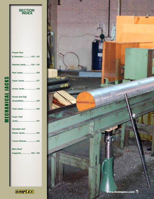
SECTION<br />
INDEX<br />
Proper Size<br />
& Selection............. 132 - 133<br />
Ratchet Jacks......... 134 - 135<br />
Reel Jacks........................136<br />
M E C H A N I C A L J A C KS<br />
Super Jacks......................137<br />
Screw Jacks.....................138<br />
Screw <strong>and</strong> Cap<br />
Assemblies.......................139<br />
Tank Jacks........................140<br />
Push / Pull<br />
Jacks.................................141<br />
Spreader <strong>and</strong><br />
Planer Jacks.....................142<br />
Trench Braces..................143<br />
Mine Roof<br />
Supports................. 144 - 145<br />
www.tksimplex.com <br />
www.tksimplex.com
INTRODUCTION<br />
MECHANICAL<br />
JACKS<br />
Multiple-toothed pawls provide<br />
greater contact with rack bar<br />
Double-lever sockets<br />
for changing h<strong>and</strong>le angle<br />
Plated Springs<br />
Resist Corrosion<br />
Adjustable Spring Links<br />
Replaceable<br />
Trunnion Bearings<br />
Ductile iron housing for<br />
maximum strength<br />
Reversing Lever<br />
3 The Industry St<strong>and</strong>ard<br />
With over a century of experience in designing <strong>and</strong> manufacturing<br />
mechanical jacks, Simplex is the undisputed market leader<br />
that has set the st<strong>and</strong>ard for high quality <strong>and</strong> reliability in the<br />
mechanical jack industry.<br />
<strong>SIMPLEX</strong> MECHANICAL JACKS PRODUCT LINE OVERVIEW<br />
Ratchet Jack Model Shown<br />
3 Unsurpassed Quality<br />
Simplex Jacks have proven to withst<strong>and</strong> the toughest application<br />
<strong>and</strong> use in today’s market. Each Jack component is carefully<br />
inspected <strong>and</strong> assembled by highly skilled assemblers <strong>and</strong> tested<br />
to meet or exceed ANSI B30.1 Safety St<strong>and</strong>ards.<br />
3 The Widest Selection<br />
Only Simplex can offer a full range of Ratchet Jacks, Screw<br />
Jacks, Superjacks, Push/Pull Jacks <strong>and</strong> Mine Roof Supports to fit<br />
a broad range of applications <strong>and</strong> use.<br />
3 Value <strong>and</strong> Service<br />
Simplex st<strong>and</strong>s behind every mechanical jack we sell with a NO<br />
SMALL PRINT WARRANTY supported by our global network of<br />
Industrial Distributors <strong>and</strong> Authorized Service Centers.<br />
131
MECHANICAL<br />
JACKS<br />
PROPER SIZE & SELECTION<br />
METHODS OF MECHANICAL FORCE<br />
Ratchet Jacks<br />
Ratcheting mechanism<br />
used to create leverage for<br />
movement.<br />
Screw Jacks<br />
Mechanical advantage is gained by using<br />
a specialized Acme threaded screw.<br />
POINTS TO REVIEW WHEN SELECTING A MECHANICAL JACK<br />
Determine the Proper Jack for your Application<br />
Ratchet jacks are designed for lifting <strong>and</strong> positioning up to 15 tons. For higher tonnage applications, you should consider<br />
using our Superjacks for lifting <strong>and</strong> sustaining up to 50 tons. For all sustaining load applications, consider the screw jack<br />
as a suitable solution up to 20 tons.<br />
H<strong>and</strong>le Effort<br />
Reference each table within this section to determine the amount h<strong>and</strong>le effort required for an application. Each model<br />
number specifies the amount of force required per ton. Also consult your local codes, safety st<strong>and</strong>ards or contracts that<br />
may specify maximum allowable h<strong>and</strong>le effort per user. Proper jack sizing is required to maintain reasonable h<strong>and</strong>le effort.<br />
Lift <strong>and</strong> Height of Jack<br />
The available clearance under the load often determines which jack should be used. For the greatest versatility, select<br />
a jack that has the longest available stroke, but still fits under the load. The ratchet jack toe can be used in very low<br />
clearance situations where other products are not suited.<br />
Travel Speed<br />
Ratchet jacks provide greatest travel per stroke, but accommodate lighter loads. Superjacks provide greater lifting<br />
capacity with less movement per stroke.<br />
Portability<br />
If ease of portability is a factor, consider lightweight Ratchet Jack models: A1022, A1538, A1029-R, A1029-L<br />
or Superjack models: A1510C, A2510C, A2515C, A3510D, A5010B.<br />
132<br />
www.tksimplex.com <br />
www.tksimplex.com
PROPER SIZE & SELECTION<br />
MECHANICAL<br />
JACKS<br />
Ratchet Jacks are ideal for mills <strong>and</strong> factory maintenance, oil fields, shipyards, farms,<br />
machinery riggers, construction contactors, mining operators, bridge <strong>and</strong> rail car repair <strong>and</strong><br />
heavy-duty industrial maintenance. These are the most versatile, general-purpose jacks available.<br />
Rugged construction permits safe, efficient lifting, lowering, skidding, moving, sustaining <strong>and</strong><br />
leveling with the important <strong>SIMPLEX</strong> feature that provides full lift capacity on the toe or on the<br />
cap.<br />
Super Jacks are used for inspecting <strong>and</strong> renewing journal brasses, bridge, tank <strong>and</strong> structural<br />
steel erectors, presses, shipbuilding <strong>and</strong> all industries where powerful, all-position jacks are<br />
required. These jacks will hold the load indefinitely <strong>and</strong> offer heat treated, alloy steel forgings,<br />
bronze nuts, ball bearings, positive shoulder stops <strong>and</strong> high gear ratios. The ratchet mechanisms<br />
are fully enclosed to protect them from the elements.<br />
Trench Braces provide a safe, efficient <strong>and</strong> economical solution for utility maintenance, along<br />
with protection against cave-ins <strong>and</strong> costly reconstruction. Blunt, drop forged steel safety lever<br />
nut prevents injuries <strong>and</strong> damage. The ball <strong>and</strong> socket joints provide maximum tilting action with<br />
lugs at each end to ensure quick adjustment <strong>and</strong> tight grip at all angles. The pipe sleeve can be used<br />
to adapt the brace to the width of the trench.<br />
Screw Jacks are suitable for house movers, leveling, supporting, shop <strong>and</strong> factory maintenance,<br />
riggers, locomotive repairs, drillers <strong>and</strong> farm applications. Malleable housings are lighter <strong>and</strong><br />
unbreakable. A hardened, large chrome-moly ball floating cap centers the load automatically <strong>and</strong><br />
reduces friction by 88%. The steel cap is constructed of corrugated, drop-forged steel with a selfleveling<br />
9 degree float.<br />
Push-Pull Jacks are essential for any maintenance repair or production work in all types of<br />
shops <strong>and</strong> field applications. Steamboat Jacks are used on the construction of bridges <strong>and</strong><br />
concrete <strong>and</strong> steel engineering projects. Gravity type pawl is used on boats <strong>and</strong> barges.<br />
Mine Roof Supports are designed for putting up cross timbers <strong>and</strong> steel beams, aligning steel mine<br />
cars, a temporary prop in connection with loading equipment, pulling up <strong>and</strong> removing slack in<br />
power cables, pulling <strong>and</strong> pushing conveyor lines <strong>and</strong> controlling the tail piece. These mine roof<br />
supports are available in a ratchet or screw style head. The A9225 double acting mechanism lifts <strong>and</strong><br />
lowers on both the up <strong>and</strong> down stroke. The 139A uses the screw type <strong>and</strong> is ideal for tight quarters.<br />
The M9 <strong>and</strong> M17 screw assemblies <strong>and</strong> bases can be adapted to a 2” pipe, which is universally used<br />
in mines with coal seams of varying heights.<br />
133
MECHANICAL<br />
JACKS<br />
Ratchet Jacks<br />
Model 85A is used to lift a CNC machine for installation. Five ton<br />
lifting capacity, low toe height <strong>and</strong> light weight make the models<br />
84A, 85A, & 86A universal tools. Ten ton models are used extensively<br />
by structural movers, riggers & maintenance crews.<br />
Ratchet Family Shown<br />
For additional models, see table.<br />
<strong>SIMPLEX</strong> ADVANTAGES<br />
4 Double-lever sockets for jacking in close<br />
quarters.<br />
4 Multiple-tooth pawls for strength & safety.<br />
4 Drop-forged, alloy steel, heat-treated<br />
components.<br />
4 Adjustable spring links for added serviceability.<br />
4 Plated springs to resist corrosion.<br />
4 Large base ensures a firm foundation.<br />
4 Supports full rated capacity on the toe or the<br />
cap.<br />
4 Steel lever bars sold separately.<br />
CARRYING HANDLE<br />
Right <strong>and</strong> left side carrying h<strong>and</strong>les make<br />
the positioning <strong>and</strong> transporting of the 10,<br />
15 <strong>and</strong> 20 ton ratchet jacks simple.<br />
HYDRAULIC JACKS<br />
Please refer to our Hydraulic Jack<br />
section for a complete line of Toe<br />
Jacks to fit your lifting needs.<br />
- Pg. 103<br />
Multiple-toothed pawls<br />
provides greater contact<br />
with rack bar.<br />
Double-lever sockets<br />
for changing h<strong>and</strong>le<br />
angle.<br />
Advisory<br />
A<br />
Please refer to pages 4 & 5 for a complete<br />
list of safety tips <strong>and</strong> recommendations to<br />
ensure that your Simplex equipment will<br />
perform to its full potential.<br />
Plated springs resist<br />
corrosion.<br />
Adjustable spring<br />
links.<br />
Replaceable<br />
trunnion bearings.<br />
Ductile iron<br />
housing for<br />
maximum strength.<br />
Reversing lever.<br />
134<br />
www.tksimplex.com
MECHANICAL<br />
JACKS<br />
Ratchet Jacks<br />
I-Beam Base Order # - 10800 Alloy Chain Order # - 10760<br />
A1538 Utility Pole Jack Shown<br />
For additional models, see table.<br />
A1538 Utility Pole Jack is used for pole lining maintenance<br />
by telephone, light, power <strong>and</strong> railroad companies <strong>and</strong> has a<br />
lightweight aluminum alloy housing. The I-Beam assures a firm<br />
foundation - ratchet jack base pivots for positioning <strong>and</strong> the<br />
alloy chain inter-connects to the jack to the pole for lifting objects<br />
upwards.<br />
36”<br />
Steel Lever Bar<br />
10640<br />
Steel Lever Bar<br />
10665<br />
60”<br />
Model<br />
A1022 Ratchet Jack Shown<br />
For additional models, see table.<br />
Supporting<br />
Cap.<br />
(tons)<br />
Lifting<br />
Cap.<br />
(tons)<br />
Stroke<br />
(in)<br />
Product Ordering & Dimensional Specifications<br />
H<strong>and</strong>le<br />
Effort<br />
per Ton<br />
(lbs)<br />
Toe<br />
Min.<br />
Height<br />
(in)<br />
Steel Lever Bar<br />
10675<br />
Base<br />
Size<br />
(in)<br />
Weight<br />
(lbs)<br />
Order<br />
Number<br />
Steel Lever Bars<br />
84A 5 5 7 32 1 3/4 5 x 7 3/8 28 10640 36 1 8<br />
85A 5 5 10 32 1 3/4 5 x 7 3/8 30 10640 36 1 8<br />
86A 5 5 13 32 1 3/4 5 x 7 3/8 35 10640 36 1 8<br />
1017 10 10 9 1/2 30 2 6 x 8 3/4 40 10665 60 1 1/4 17<br />
A1022 10 10 12 30 2 1/4 6 1/2 x 10 1/4 42 10665 60 1 1/4 17<br />
22B 10 10 12 30 2 1/4 6 1/2 x 10 1/4 70 10665 60 1 1/4 17<br />
A1538 15 8 22 32 ----- 8 x 8 1/4 62 10675 72 1 1/4 20<br />
24A 20 15 13 32 2 1/4 8 x 10 1/4 93 10675 72 1 1/4 20<br />
2029 20 15 18 32 2 1/4 8 x 11 104 10675 72 1 1/4 20<br />
72”<br />
Length<br />
(in)<br />
Dia.<br />
(in)<br />
Weight<br />
(lbs)<br />
Note: 10665 & 10675 lever bars are interchangeable. The longer 10675 bar results in lower h<strong>and</strong>le efforts.<br />
135
MECHANICAL<br />
JACKS<br />
Reel Jacks<br />
Using A1029-R <strong>and</strong> A1029-L, utilities can easily h<strong>and</strong>le large<br />
reels. The large wooden bases <strong>and</strong> low h<strong>and</strong>le efforts enhance<br />
safety <strong>and</strong> reduce operator fatigue. Simplex Reel Jacks are also<br />
an excellent choice for wire rope <strong>and</strong> sling manufacturers.<br />
<strong>SIMPLEX</strong> ADVANTAGES<br />
4 Double-lever sockets for jacking in close<br />
quarters.<br />
4 Multiple-tooth pawls for strength & safety.<br />
4 Drop-forged, alloy steel, heat-treated<br />
components.<br />
4 Adjustable spring links for added serviceability.<br />
4 Plated springs to resist corrosion.<br />
4 Tough hardwood bases laminated for extra<br />
strength.<br />
4 Precision machining throughout.<br />
4 Steel lever bars sold separately.<br />
Reel Jack Family Shown<br />
For additional models, see table.<br />
Steel Lever Bar<br />
10640<br />
36”<br />
CARRYING HANDLES<br />
Convenient center mounted<br />
carrying h<strong>and</strong>le makes this jack<br />
easy to position <strong>and</strong> move.<br />
LAMINATED BASE<br />
Treated laminated hardwood base<br />
provides solid support along with<br />
durability to withst<strong>and</strong> harsh<br />
conditions.<br />
Steel Lever Bar<br />
10665<br />
60”<br />
* 10675 Lever Bar can be substituted with order number 10665 for reduced h<strong>and</strong>le effort.<br />
Product Ordering & Dimensional Specifications<br />
Model Capacity per Pair H<strong>and</strong>le<br />
Effort<br />
per Ton<br />
(lbs)<br />
Stroke<br />
(in)<br />
Reel<br />
Dia.<br />
(in)<br />
Top<br />
Hook<br />
Height<br />
(in)<br />
Weight<br />
(lbs)<br />
Side<br />
Hooks<br />
(tons)<br />
Top<br />
Hooks<br />
(tons)<br />
Order<br />
Number<br />
Steel Lever Bars<br />
320B 5 10 32 10 20-60 21 51 10640 36 1 8<br />
321B 10 20 22 12 20-96 34 1/2 128 *10665 60 1 1/4 17<br />
A1029-R 10 20 22 11 5/8 36-84 31 1/8 86 *10665 60 1 1/4 17<br />
A1029-L 10 20 22 11 5/8 36-84 31 1/8 86 *10665 60 1 1/4 17<br />
136 www.tksimplex.com <br />
Length<br />
(in)<br />
Dia.<br />
(in)<br />
Weight<br />
(lbs)
MECHANICAL<br />
JACKS<br />
Super Jacks<br />
Outdoor use <strong>and</strong> weld splatter can shorten the life of st<strong>and</strong>ard<br />
jacks. “We chose Simplex Superjacks for the bullet proof<br />
construction <strong>and</strong> holding power.” They provide trouble-free<br />
service in the roughest applications.<br />
<strong>SIMPLEX</strong> ADVANTAGES<br />
4 Ratcheting screw jack design.<br />
4 Holds the load indefinitely without creep<br />
down.<br />
4 Positive Shoulder Stops for safety.<br />
4 Available with aluminum or ductile iron housing.<br />
4 Ball Bearings for smooth operation & low<br />
h<strong>and</strong>le effort.<br />
4 Jacking capacity ranges 15 - 50 tons.<br />
4 Low backsaving h<strong>and</strong>le effort.<br />
4 Steel lever bars sold separately.<br />
Super Jack Family Shown<br />
For additional models, see table.<br />
REVERSAL RATCHET<br />
Raise or lower the load precisely<br />
with the reversal ratchet socket<br />
with quick spin h<strong>and</strong>le.<br />
36”<br />
LOAD CAP<br />
Steel serrated load cap prevents<br />
the load from possible slippage.<br />
56”<br />
Steel Lever Bar<br />
10640<br />
Steel Lever Bar<br />
10660<br />
Product Ordering & Dimensional Specifications<br />
Model<br />
Cap.<br />
(tons)<br />
Min.<br />
Height<br />
(in)<br />
Stroke<br />
(in.)<br />
H<strong>and</strong>le<br />
Effort Per<br />
Ton (lbs.)<br />
Base<br />
Dia.<br />
(in)<br />
Weight<br />
(lbs)<br />
Order<br />
Number<br />
Steel Lever Bars<br />
Length<br />
(in)<br />
A1510C 15 10 1/4 5 9 5 1/2 28 10640 36 1 8<br />
2510C 25 10 1/4 5 6 5 1/2 43 10640 36 1 8<br />
A2510C 25 10 1/4 5 6 5 1/2 34 10640 36 1 8<br />
A2515C 25 15 9 6 5 1/2 43 10640 36 1 8<br />
3510D 35 10 1/4 5 5 5 1/2 44 10640 36 1 8<br />
A3510D 35 10 1/4 5 5 5 1/2 34 10640 36 1 8<br />
5010B 50 10 5/16 4 4 7 1/4 80 10660 56 1 1/8 16<br />
A5010B 50 10 5/16 4 4 7 1/4 61 10660 56 1 1/8 16<br />
Dia.<br />
(in)<br />
Weight<br />
(lbs)<br />
137
MECHANICAL<br />
JACKS<br />
Screw Jacks<br />
Simplex screw jacks are used to adjust the height of this roller<br />
fixture. “We use this fixture during the assembly of long pieces<br />
of screw stock.” “Simplex screw jacks makes fixturing easy <strong>and</strong><br />
precise.”<br />
<strong>SIMPLEX</strong> ADVANTAGES<br />
4 Ductile iron bodies for strength.<br />
4 Positive welded stop for safety.<br />
4 Supports loads indefinitely, <strong>and</strong> won’t creep<br />
down.<br />
4 Carry h<strong>and</strong>le for ease of transport.<br />
4 Steel lever bars sold separately.<br />
4 Four way head for easy positioning of lever bar.<br />
4 Tilt saddle assists in centering load point.<br />
Mechanical Screw Jack Family Shown<br />
See table for additional models.<br />
24”<br />
LOAD CAP<br />
Drop forged steel load cap is<br />
serrated to prevent load slippage.<br />
SITE HOLE<br />
Built in site hole for safety,<br />
allows the user to determine the<br />
height of the lifting screw<br />
without guessing.<br />
Steel Lever Bar<br />
10621<br />
- 36" <strong>and</strong> 42" Lengths Also Available - See Table -<br />
Model<br />
Order<br />
Number<br />
Sustaining<br />
Capacity<br />
(tons)<br />
Product Ordering & Dimensional Specifications<br />
Closed<br />
Height<br />
(in)<br />
Stroke<br />
(in)<br />
H<strong>and</strong>le<br />
Effort<br />
Per Ton<br />
(lbs)<br />
2 1/2 x 18 03300 24 23 14 1/4 15 8 1/2 52 10655 42 1 1/8 12<br />
138 www.tksimplex.com <br />
Base<br />
Dia.<br />
(in)<br />
Weight<br />
(lbs)<br />
Order<br />
Number<br />
Steel Lever Bars<br />
1 1/2 x 6 03060 12 9 3/4 3 3/4 16 4 3/4 10 10621 24 3/4 4<br />
1 1/2 x 8 03090 12 11 5/8 5 3/4 16 5 1/2 12 10621 24 3/4 4<br />
1 1/2 x 12 03120 12 15 5/8 9 3/4 16 6 1/4 16 10621 24 3/4 4<br />
2 x 8 03165 20 11 3/4 5 15 6 17 10635 36 13/16 6<br />
2 x 10 03195 20 13 3/4 7 15 6 1/2 20 10635 36 13/16 6<br />
2 x 12 03210 20 15 3/4 9 15 6 3/4 24 10635 36 13/16 6<br />
2 1/2 x 8 03240 24 13 4 1/4 15 6 1/2 28 10655 42 1 1/8 12<br />
2 1/2 x 12 03255 24 17 8 1/4 15 7 1/4 37 10655 42 1 1/8 12<br />
Length<br />
(in)<br />
Dia.<br />
(in)<br />
Weight<br />
(lbs)
MECHANICAL<br />
JACKS<br />
Screw & Cap Assemblies<br />
The shoulder nut is placed into piping,<br />
fixtures or other fixed forms supplied by<br />
the user.<br />
144 Screw <strong>and</strong> Cap assemblies support the outer wall of a large<br />
generator assembly at the Gr<strong>and</strong> Coulee Dam. The assemblies<br />
also are used to exert pressure, stabilizing the generator<br />
laminations.<br />
<strong>SIMPLEX</strong> ADVANTAGES<br />
4 Holds the load indefinitely without creep<br />
down.<br />
4 Versatile accessories for outrigger supports,<br />
holding <strong>and</strong> adjusting concrete forms, or for any<br />
application requiring special holding or shoring<br />
support.<br />
4 The shoulder nut is placed into piping or another<br />
fixed form, <strong>and</strong> the screw & cap assembly<br />
is threaded through it.<br />
4 Four-way head assembly accommodates the<br />
lever bar at four different positions for infinite<br />
height adjustments <strong>and</strong> exact leveling.<br />
4 Drop forged serrated steel cap floats 9° on a<br />
chrome-moly ball, reducing friction by 88%.<br />
Advisory<br />
A<br />
Please refer to pages 4 & 5 for a<br />
complete list of safety tips <strong>and</strong><br />
recommendations to ensure that<br />
your Simplex equipment will<br />
perform to its full potential.<br />
B<br />
C<br />
E<br />
A<br />
D<br />
D<br />
C<br />
B<br />
A<br />
E<br />
F<br />
Model<br />
Order<br />
Number<br />
Sustaining<br />
Capacity<br />
(tons)<br />
Product Ordering & Dimensional Specifications<br />
Modified Acme<br />
Thread Dia.- Pitch<br />
A (Thread)<br />
B<br />
(in)<br />
C<br />
(in)<br />
Dimensions<br />
D<br />
(in)<br />
E<br />
(in)<br />
F<br />
(in)<br />
Weight<br />
(lbs)<br />
Order<br />
Number<br />
Steel Lever Bars<br />
1 1/2 BC-30-6 03568 12 1 1/2 - 3 2 7/8 2 1/4 7/8 3 3/4 5 11/16 5 1/2 10621 24 3/4 4<br />
1 1/2 BC-30-8 03570 12 1 1/2 - 3 2 7/8 2 1/4 7/8 3 3/4 7 11/16 6 1/4 10621 24 3/4 4<br />
1 1/2 BC-30-12 03574 12 1 1/2 - 3 2 7/8 2 1/4 7/8 3 3/4 11 11/16 7 3/4 10621 24 3/4 4<br />
2 BC-30-8 03582 20 2 - 2 1/2 3 1/8 2 7/8 15/16 4 7 9/16 10 1/2 10635 36 13/16 6<br />
2 BC-30-10 03584 20 2 - 2 1/2 3 1/8 2 7/8 15/16 4 9 9/16 12 10635 36 13/16 6<br />
2 BC-30-12 03586 20 2 - 2 1/2 3 1/8 2 7/8 15/16 4 11 9/16 13 1/2 10635 36 13/16 6<br />
2 1/2 BC-30-8 03600 24 2 1/2 - 2 1/2 3 1/4 3 1/4 1 3/16 5 1/16 7 13/16 16 3/4 10655 42 1 1/8 12<br />
2 1/2 BC-30-12 03602 24 2 1/2 - 2 1/2 3 1/4 3 1/4 1 3/16 5 1/16 11 13/16 21 3/4 10655 42 1 1/8 12<br />
2 1/2 BC-30-18 03608 24 2 1/2 - 2 1/2 3 1/4 3 1/4 1 3/16 5 1/16 17 13/16 29 1/4 10655 42 1 1/8 12<br />
Shoulder Nuts<br />
1 1/2 NS-25 03620 ---- 1 1/2 - 3 3 2 13/32 3 2 1/4 ---- 3 1/4<br />
2 NS-25 03625 ---- 2 - 2 1/2 4 3 3 1/4 2 1/4 ---- 5<br />
2 1/2 NS-25 03630 ---- 2 1/2 - 2 1/2 5 3 15/16 4 3 ---- 11<br />
Length<br />
(in)<br />
Dia.<br />
(in)<br />
Weight<br />
(lbs)<br />
139
MECHANICAL<br />
JACKS<br />
TANK JACKS<br />
Model<br />
Use the installation <strong>data</strong> charts, with accompanying drawings, to determine the size<br />
<strong>and</strong> number of jacks your application will require.<br />
140<br />
Tank<br />
Dia.<br />
(ft-in)<br />
Pipe<br />
Dia.<br />
(in)<br />
“DB”<br />
(in)<br />
“HB”<br />
(in)<br />
For Side Pipe Connections<br />
“CB”<br />
(in)<br />
Qty. Required<br />
Under<br />
12 Ft.<br />
Over<br />
12 Ft.<br />
4406 3-6 --- 14 6 1/2 4 4 4<br />
4406 4-0 --- 16 6 3/8 3 1/2 4 4<br />
4406 4-6 --- 18 6 3/4 3 1/2 4 4<br />
4406 5-0 --- 20 7 1/8 3 1/2 4 4<br />
4406 5-6 --- 22 7 1/2 3 1/2 4 4<br />
4406 6-0 --- 24 6 1 1/2 4 4<br />
4406 6-6 --- 26 6 1/8 1 1/2 4 4<br />
4406 7-0 --- 28 6 1/2 1 1/2 4 6<br />
4406 7-6 --- 30 6 7/8 1 1/2 4 6<br />
4406 8-0 --- 32 7 1/4 1 1/2 6 8<br />
4406 8-6 --- 34 7 5/8 1 1/2 6 8<br />
4406 9-0 --- 36 8 1 1/2 6 8<br />
4410 9-6 --- 38 10 3/8 3 1/2 8 8<br />
4410 10-0 --- 42 10 3/4 3 1/2 8 8<br />
For Bottom Pipe Connections<br />
4410 3-6 2 14 10 1/2 8 4 4<br />
4410 4-0 2 1/2 16 11 7/8 9 4 4<br />
4410 4-6 2 1/2 18 12 1/4 9 4 4<br />
4414 5-0 2 1/2 20 14 5/8 11 4 4<br />
4414 5-6 2 1/2 22 15 11 4 4<br />
4414 6-0 3 24 16 3/8 12 4 4<br />
4414 6-6 3 26 14 5/8 10 4 4<br />
4418 7-0 4 28 18 1/4 13 1/4 4 6<br />
4418 7-6 4 30 18 5/8 13 1/4 4 6<br />
4418 8-0 4 32 19 13 1/4 6 8<br />
4418 8-6 5 35 20 14 6 8<br />
4418 9-0 5 37 19 1/2 13 6 8<br />
4418 9-6 5 39 20 13 8 8<br />
4418 10-0 6 41 21 14 8 8<br />
Product Ordering & Dimensional Specifications<br />
<strong>SIMPLEX</strong> FILTER & STORAGE TANK JACKS<br />
Simplex Tank Jacks offer an economical means of supporting<br />
<strong>and</strong> leveling vertical, bottom, or side-opening filter <strong>and</strong><br />
storage tanks. Screw operation provides infinite adjustment<br />
for exact tank leveling <strong>and</strong> gravity flow. Rated capacity for<br />
all models is 15,000 lbs.<br />
C1025 steel saddle is welded to the tank before being set<br />
on the jack.<br />
Model<br />
Order<br />
Number<br />
Base<br />
Dia. "A"<br />
(in)<br />
Base<br />
Height “B”<br />
(in)<br />
Min.<br />
Height “C”<br />
(in)<br />
Max. Weight<br />
Height “C” (lbs)<br />
(in)<br />
4406 03820 5 3/4 4 6 8 10<br />
4410 03840 6 8 10 12 12<br />
4414 03860 6 1/2 12 14 16 17<br />
4418 03880 8 16 18 20 26<br />
Saddle 03993 ----- ----- ----- ----- 2.5<br />
HB<br />
CB<br />
DB<br />
DB<br />
CB<br />
HB<br />
www.tksimplex.com <br />
www.tksimplex.com
2 3/8” 5/16”<br />
PUSH / PULL JACKS<br />
MECHANICAL<br />
JACKS<br />
<strong>SIMPLEX</strong> STEAMBOAT JACK<br />
These 20 ton capacity models are used for connecting<br />
river barges, pulling forms <strong>and</strong> steel plates together <strong>and</strong><br />
other applications in bridge construction <strong>and</strong> concrete <strong>and</strong><br />
steel engineering projects. Units are equipped with spring<br />
activated pawls <strong>and</strong> 26” long attached h<strong>and</strong>les. The h<strong>and</strong>le<br />
effort per ton is 16 lbs. The I.D. of the eye is 1 5/16” . Depth<br />
of eye is 1 7/8” .<br />
Product Ordering & Dimensional Specifications<br />
Model Dim.<br />
“A”<br />
Travel<br />
Length<br />
Barrel<br />
Length<br />
Screw<br />
Dia.<br />
Weight<br />
(lbs)<br />
(in) (in) (in) (in)<br />
ER-10 23 14 18 2 57<br />
ER-20 29 20 24 2 66<br />
ER-30 35 26 30 2 74<br />
ER-40 47 38 42 2 92<br />
A<br />
<strong>SIMPLEX</strong> 610 PUSH/PULL JACK<br />
The model 610 is used for pushing or pulling, holding & more;<br />
ideal for weld shops. For added versatility, the end nuts are<br />
designed to permit the use of chains with eye hooks. Steel<br />
lever bar is ordered separately.<br />
<strong>SIMPLEX</strong> 610-15 RATCHET SCREW ASSEMBLY<br />
The ratchet screw assembly may be custom adapted to<br />
almost any push/pull application such as adjusting forms,<br />
fixtures, doors, flues, <strong>and</strong> dampers. Incorporates 1 1/4 - 6<br />
Acme class 2G, right <strong>and</strong> left h<strong>and</strong> thread.<br />
Min 3 3/8”<br />
Max 8 1/8” 3 3/16”<br />
1”<br />
1 1/4”<br />
3/4”<br />
Min 2 7/8”<br />
Max 7 5/8”<br />
10”<br />
5/16”<br />
Model<br />
Centered<br />
Capacity<br />
(tons)<br />
Hook/Toe<br />
Offset Load<br />
Capacity<br />
(tons)<br />
Product Ordering & Dimensional Specifications<br />
Travel<br />
(in)<br />
H<strong>and</strong>le<br />
Effort Per<br />
Ton<br />
(lbs)<br />
Screw<br />
Dia.<br />
(in)<br />
Length<br />
(in)<br />
Weight<br />
(lbs)<br />
Order<br />
Number<br />
Steel Lever Bars<br />
610 10 2 4 1/2 15 1 1/4 10 13 10621 24 3/4 4<br />
610-15 10 2 ---- 15 1 1/4 ---- 5 10621 24 3/4 4<br />
Length<br />
(in)<br />
Dia.<br />
(in)<br />
Weight<br />
(lbs)<br />
141
MECHANICAL<br />
JACKS<br />
SPREADER & PLANER JACKS<br />
SPREADER JACK<br />
The model 3A Spreader Jack is used when working in close<br />
quarters. The Spreader Jack has a closed height of only 3”, with<br />
1” stroke for adjustments, yet it can support 3 tons. The serrated<br />
cap rotates to prevent twist out, but does not pivot. The Spreader<br />
Jack may also be used as a planer jack.<br />
Model<br />
Product Ordering & Dimensional Specifications<br />
Sustaining<br />
Cap.<br />
(tons)<br />
Minimum<br />
Height<br />
(in)<br />
Operable<br />
Rise<br />
(in)<br />
“A”<br />
Across<br />
Flats (in)<br />
Weight<br />
(lbs)<br />
3A 3 3 1 2 3 1/4<br />
A<br />
Spreader Jack 3A Shown<br />
PLANER JACKS<br />
Four different models are available, with capacities ranging from 2 to 8<br />
tons. They are used in leveling work on plane beds, millers <strong>and</strong> other<br />
machinery.<br />
Screw’s operation provides infinite height adjustments for exact<br />
leveling. The side-locking screw keeps the jack extended <strong>and</strong> prevents<br />
lowering due to vibration. The ball <strong>and</strong> socket cap swivels to center<br />
load forces. The notched base fastens easily to machine beds.<br />
142<br />
2P Planer Jack Shown<br />
A<br />
Product Ordering & Dimensional Specifications<br />
Model Sustaining<br />
Cap.<br />
Minimum<br />
Height<br />
Operable<br />
Rise<br />
“A”<br />
Across<br />
Weight<br />
(lbs)<br />
(tons) (in) (in) Flats (in)<br />
1P 2 2 3/4 1 2 3/8 1 1/2<br />
2P 4 3 3/4 1 1/2 3 1/8 3<br />
3P 6 5 1/4 2 1/4 4 6<br />
4P 8 7 1/2 4 5 3/8 12<br />
www.tksimplex.com <br />
www.tksimplex.com
TRENCH BRACES<br />
MECHANICAL<br />
JACKS<br />
Simplex Trench Braces provide efficient, economical protection<br />
against cave-ins <strong>and</strong> costly redigging in construction <strong>and</strong> utility<br />
maintenance. Braces extend by turning the lever nut h<strong>and</strong>le. The<br />
ball socket joints tilt for added safety on angular mounting. Holes<br />
on each end facilitate mounting to wood members.<br />
Simplex trench braces are designed for use with st<strong>and</strong>ard schedule<br />
40 pipe. Screw end models SE-12, SE-16 <strong>and</strong> butt end model BE-<br />
25 use 1 1/2” diameter pipe. Model SE-18 <strong>and</strong> butt end BE-35 use<br />
2” diameter pipe. Pipe should be cut to length based on the chart<br />
below <strong>and</strong> drawing in Fig. 1.<br />
Butt End<br />
Screw End<br />
SE12 Shown<br />
Dimensions assume the use of both screw & butt ends together as an assembly.<br />
Product Ordering & Dimensional Specifications<br />
Model Adjust Pipe Butt<br />
Range Size End<br />
(in) (in)<br />
“A”<br />
Min. Pipe<br />
Length<br />
(in)<br />
“B”<br />
Min.<br />
Closed<br />
Ht. (in)<br />
SE-12 7 1 1/2 BE-25 12 18<br />
SE-16 10 1 1/2 BE-25 16 22<br />
SE-18 10 2 BE-35 18 25 1/2<br />
B<br />
A<br />
Schedule 40<br />
1 1/2” or 2” Pipe<br />
(Fig. 1) All Trench Brace Models<br />
Quick Reference Timber / Trench Brace Equivalency Tables*<br />
The following charts are based on OSHA Timber/Trench Brace Charts* which do not consider transverse loading conditions.<br />
Product Ordering & Dimensional Specifications<br />
Trench<br />
Depth<br />
(ft)<br />
5 to<br />
10<br />
10 to 15<br />
Horizontal<br />
Spacing<br />
(ft)<br />
Width of Trench (ft)<br />
up to 4 up to 6 up to 8<br />
Cross Brace Wales Uprights (in)<br />
Vertical<br />
Spacing<br />
(ft)<br />
Size<br />
(in)<br />
Vertical<br />
Spacing<br />
(ft)<br />
Max. Allowable<br />
Horizontal Spacing (ft)<br />
4’ 5’ 6’ 8’<br />
Soil Type - A P a = 25 x H + 72 psf (2ft. Surcharge)<br />
SE12 SE12<br />
up to 6<br />
SE18 4<br />
SE16 SE16<br />
--- --- 2”x 6” ---<br />
---<br />
SE12 SE12<br />
up to 8<br />
SE18 4<br />
SE16 SE16<br />
--- --- --- 2”x 6”<br />
up to 10 SE18 SE18 SE18 4 8 x 8 4 --- 2”x 6” --- ---<br />
up to 12 SE18 SE18 --- 4 8 x 8 4 --- --- 2”x 6 ” ---<br />
up to 6<br />
SE12<br />
SE16<br />
SE12<br />
SE16<br />
SE18 4 --- --- --- 3”x 8” ---<br />
up to 8 SE18 SE18 --- 4 8 x 8 4 2”x 6” --- --- ---<br />
Soil Type - B P a = 45 x H + 72 psf (2ft. Surcharge)<br />
Trench<br />
Depth<br />
(ft)<br />
5 to<br />
10<br />
Horizontal<br />
Spacing<br />
(ft)<br />
Cross Brace<br />
Vertical<br />
Spacing<br />
(ft)<br />
Wales<br />
Uprights (in)<br />
Max. Allowable<br />
Horizontal Spacing (ft)<br />
Width of Trench (ft)<br />
Vertical<br />
Size<br />
Spacing<br />
(in)<br />
up to 4 up to 6 (ft)<br />
3’<br />
up to 6 SE-18 SE-18 5 6 x 8 5 2”x 6”<br />
143
MECHANICAL<br />
JACKS<br />
MINE ROOF SUPPORTS<br />
Simplex head assemblies are designed for roof support in mines<br />
<strong>and</strong> other areas where ceiling heights vary greatly. Use your own<br />
pipe to custom build a support for nearly any application.<br />
Head Assembly<br />
Model 09167<br />
Type S Head<br />
36 square inches<br />
in support area.<br />
The 8 ton MS-9 models use 2” schedule 40 pipe. The 16 ton MS-17<br />
models require 2” schedule 80 pipe. A round base (ordered separately)<br />
is available to fit the 2” pipe. All models incorporate a lever<br />
nut h<strong>and</strong>le. The 8 ton models are available with either FS or S style<br />
heads, <strong>and</strong> the 16 ton model is available with FS style head only.<br />
For economy, use the import version. If U.S. manufacture is<br />
required, use the domestic version. Simplex quality is assured with<br />
either choice.<br />
Base Assembly<br />
Model 09220<br />
Type FS Head<br />
For support with wooden<br />
or rubber cap pieces.<br />
✔<br />
✔<br />
✔<br />
✔<br />
Maximum pipe length recommendations are based<br />
upon the following conditions:<br />
• Fully extended assemblies loaded to maximum rated capacity.<br />
• Head <strong>and</strong> base securely fixed to prevent lateral movement.<br />
• Schedule 40 pipe with a minimum yield strength of 35,000 psi/8<br />
ton models.<br />
• Schedule 80 pipe with a minimum yield strength of 48,000 psi/16<br />
ton model.<br />
Product Ordering & Dimensional Specifications<br />
A<br />
B<br />
A<br />
B<br />
Model<br />
“A”<br />
Min. Pipe<br />
Length (in)<br />
“B”<br />
Min. Closed<br />
Height (in)<br />
MS9L-FS 20 1/2 27<br />
MS9L-S 20 5/8 25 1/2<br />
MS17L-FS 21 3/4 28 3/4<br />
09167 & 09267<br />
09309<br />
Mine Roof Support Head Assemblies<br />
Model<br />
Order<br />
Number<br />
Domestic<br />
Product Ordering & Dimensional Specifications<br />
Order Number<br />
Import<br />
Head<br />
Style<br />
Sustaining<br />
Capacity<br />
(tons)<br />
Stroke<br />
(in)<br />
*Max.<br />
Pipe<br />
Length<br />
(in)<br />
Max.<br />
Extended Ht.<br />
(in)<br />
Dim.<br />
Between<br />
Flanges<br />
(in)<br />
MS9L-FS 09167 09267 FS 8 15 51 3/4 73 5 3/4 19<br />
MS9L-S 09233 -------- S 8 15 73 1/4 93 --- 19<br />
MS17L-FS ---- 09309 FS 16 15 46 1/4 68 5 3/4 34<br />
Base MB-17 09220 -------- --- 16 --- --- --- --- 6<br />
Weight<br />
(lbs)<br />
144<br />
www.tksimplex.com <br />
www.tksimplex.com
MINE ROOF SUPPORTS<br />
MECHANICAL<br />
JACKS<br />
The A9225 Family is rated at 4 tons sustaining capacity, <strong>and</strong> is suitable for a wide range<br />
of mine maintenance applications. The aluminum alloy housing <strong>and</strong> base, coupled with<br />
a convenient carrying h<strong>and</strong>le, make this unit exceptionally light <strong>and</strong> portable.<br />
The A9225 Family incorporates a ratchet mechanism for speedy operation. Lever bar<br />
#10635 is ordered separately.<br />
The 139A Family is a screw extension type roof support rated at 5 tons sustaining<br />
capacity. Designed for use as a safety prop, the 139A Family is suitable for cross<br />
timbering with wood or steel beams.<br />
Complete Unit Ratchet Lever Series - A9225 Family<br />
Mine Support<br />
A9225<br />
Mine Support<br />
139A<br />
Product Ordering & Dimensional Specifications<br />
Model<br />
Order<br />
Number<br />
Minimum<br />
Height (in)<br />
Stroke<br />
(in)<br />
Weight<br />
(lbs)<br />
Complete Unit Ratchet Lever Series - A9225 Family<br />
E 09602 39 20 29<br />
F 09603 39 20 29<br />
S 09620 39 20 29<br />
E 09606 45 26 33<br />
F 09607 45 26 33<br />
S 09621 45 26 33<br />
E 09610 57 38 36<br />
F 09611 57 38 36<br />
S 09622 57 38 36<br />
E 09614 69 38 39<br />
F 09615 69 38 39<br />
S 09623 69 38 39<br />
E 09616 75 38 42<br />
F 09617 75 38 42<br />
S 09624 75 38 42<br />
E 09618 88 38 48<br />
F 09619 88 38 48<br />
S 09625 88 38 48<br />
Complete Unit Screw Extension Series - 139A Family<br />
E 09802 42 24 50<br />
F 09803 42 24 50<br />
S 09820 42 24 50<br />
E 09806 48 30 52<br />
F 09807 48 30 52<br />
S 09821 48 30 52<br />
E 09810 54 36 54<br />
F 09811 54 36 54<br />
S 09822 54 36 54<br />
E 09814 66 36 58<br />
F 09815 66 36 58<br />
S 09823 66 36 58<br />
E 09818 78 36 64<br />
F 09819 78 36 64<br />
S 09824 78 36 64<br />
H E A D S T Y L E S<br />
E Type Head<br />
For all st<strong>and</strong>ard work. Dimension<br />
between flanges: 8 1/8”.<br />
F Type Head<br />
For use with electrical wiring.<br />
Dimension between flanges:<br />
10 1/4” .<br />
S Type Head<br />
36 square inches in support area.<br />
145