High-precision Absolute Distance Measurement using Frequency ...
High-precision Absolute Distance Measurement using Frequency ...
High-precision Absolute Distance Measurement using Frequency ...

You also want an ePaper? Increase the reach of your titles
YUMPU automatically turns print PDFs into web optimized ePapers that Google loves.
<strong>High</strong>-<strong>precision</strong> <strong>Absolute</strong> <strong>Distance</strong> <strong>Measurement</strong><br />
<strong>using</strong> <strong>Frequency</strong> Scanned Interferometry<br />
Hai-Jun Yang, Jason Deibel, Sven Nyberg, Keith Riles<br />
Department of Physics, University of Michigan, Ann Arbor, MI 48109-1120, USA<br />
(Dated: March 25, 2004)<br />
In this letter, we report high-<strong>precision</strong> absolute differential distance<br />
measurements performed with frequency scanned interferometry (FSI). <strong>Absolute</strong><br />
differential distance was determined by counting the interference fringes<br />
produced while scanning the laser frequency. A high-finesse Fabry-Perot interferometer<br />
was used to determine frequency changes during scanning. Two new<br />
multi-distance-measurement analysis techniques were developed to improve<br />
distance <strong>precision</strong> and to extract the amplitude & frequency of vibrations<br />
present during measurements. Under laboratory conditions, a <strong>precision</strong> of 50<br />
nm was demonstrated for a differential distance of approximately 0.7 meters.<br />
c○ 2004 Optical Society of America<br />
OCIS codes: 120.0120, 120.3180, 120.2650, 120.7280<br />
1. Introduction<br />
The motivation for this project is to design a novel optical system for quasi-real time<br />
alignment of tracker detector elements used in <strong>High</strong> Energy Physics (HEP) experiments.<br />
A.F. Fox-Murphy et.al. from Oxford University reported their design of a<br />
frequency scanned interferometer (FSI) for precise alignment of the ATLAS Inner<br />
Detector. 1 Given the demonstrated need for improvements in detector performance,<br />
we plan to design an enhanced FSI system to be utilized for the alignment of tracker<br />
elements used in the next generation of electron positron Linear Collider (NLC) detectors.<br />
Current plans for future detectors require a spatial resolution for signals<br />
from a tracker detector such as a silicon microstrip or silicon drift detector to be approximately<br />
7-10 µm. 2 To achieve this required spatial resolution, the measurement<br />
<strong>precision</strong> of absolute distance changes of tracker elements in one dimension should be<br />
on the order of 1 µm. Simultaneous measurements from hundreds of interferometers<br />
will be used to determine the 3-dimensional positions of the tracker elements.<br />
We describe here a demonstration FSI system built in the laboratory for initial<br />
feasibility studies. The main goal was to determine the potential accuracy of<br />
absolute distance measurements (ADM’s) that could be achieved under laboratory<br />
conditions. Secondary goals included estimating the effects of vibrations and studying<br />
error sources crucial to the absolute distance accuracy. A significant amount of<br />
research on ADM’s <strong>using</strong> wavelength scanning heterodyne interferometers already<br />
exists. 3,4 In one of the more comprehensive publications on this subject, Stone et<br />
al. describe in detail a wavelength scanning heterodyne interferometer consisting of a<br />
system built around both a reference and a measurement interferometer. 4 In addition,<br />
this system also requires an acousto-optic modulator and polarization optics.<br />
1
We believe our work represents a significant enhancement in the field of FSI in<br />
that ADM’s are performed <strong>using</strong> a simple apparatus. <strong>High</strong>-<strong>precision</strong> measurements<br />
can be carried out <strong>using</strong> a tunable laser, a simple two-arm interferometer, an off-theshelf<br />
Fabry Perot interferometer, and novel data analysis and extraction techniques.<br />
Two new multi-distance-measurement analysis techniques are presented, to improve<br />
<strong>precision</strong> and to extract the amplitude and frequency of vibrations. Major statistical<br />
and systematic uncertainties are also estimated in this letter.<br />
2. Principles<br />
The intensity I of any two-beam interferometer can be expressed as<br />
I = I 1 + I 2 + 2 √ I 1 I 2 cos(φ 1 − φ 2 ) (1)<br />
where I 1 and I 2 are the intensities of the two combined beams, φ 1 and φ 2 are the<br />
phases. Assuming the optical path lengths of the two beams are L 1 and L 2 , the phase<br />
difference in Eq. (1) is Φ = φ 1 −φ 2 = 2π|L 1 −L 2 |(ν/c), where ν is the optical frequency<br />
of the laser beam, and c is the speed of light.<br />
For a fixed path interferometer, as the frequency of the laser is continuously<br />
scanned, the optical beams will constructively and destructively interfere, ca<strong>using</strong><br />
“fringes”. The number of fringes ∆N is<br />
∆N = |L 1 − L 2 |(∆ν/c) = L∆ν/c (2)<br />
where L is the optical path difference between the two beams, and ∆ν is the scanned<br />
frequency range. The optical path difference can be determined by counting interference<br />
fringes while scanning the laser frequency. The actual differential distance can<br />
then be determined if the average refractive index over the optical path is known.<br />
In order to determine an absolute distance L 1 to a desired <strong>precision</strong>, the reference<br />
distance L 2 must be known to a better <strong>precision</strong>. Here we report only the <strong>precision</strong><br />
of the differential distance.<br />
3. Demonstration System of FSI<br />
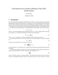
A schematic of the demonstration FSI system is shown in Fig. 1. The light source<br />
is a New Focus Velocity 6308 tunable laser (665.1 nm < λ < 675.2 nm). A highfinesse<br />
(> 200) Thorlabs SA200 Fabry-Perot Interferometer is used to measure the<br />
frequency range scanned by the laser. Data acquisition is accomplished <strong>using</strong> a National<br />
Instruments DAQ card capable of simultaneously sampling 4 channels at a rate<br />
of 5 MS/s/ch with a <strong>precision</strong> of 12-bits. Omega thermistors with a tolerance of 0.02<br />
K and a <strong>precision</strong> of 0.01 mK were used to monitor temperature. The apparatus was<br />
supported by a damped Newport optical table.<br />
In order to reduce air flow and temperature fluctuations, a transparent plastic<br />
box was constructed on top of the optical table. PVC pipes were installed to shield<br />
the volume of air surrounding the laser beam. The typical standard deviation (RMS)<br />
of 20 temperature measurements monitored for 20 seconds was approximately 50 mK<br />
for a thermistor placed outside of the box. Inside the PVC pipes, the typical standard<br />
2
deviation of 20 temperature measurements was about 0.5 mK. The interval 20 seconds<br />
is the approximate duration of the laser scan at a scan rate of 0.5 nm/s. Temperature<br />
fluctuations were suppressed by a factor of approximately 100 by employing the plastic<br />
box and PVC pipes.<br />
4. Analysis and Results<br />
For a FSI system, drifts and vibrations occurring along the optical path during the<br />
scan will be magnified by a factor of Ω = ν/∆ν, where ν is the average optical<br />
frequency of the laser beam and ∆ν is the scanned frequency. For the full scan of our<br />
laser, Ω ∼ 67. Small vibrations and drift errors that have negligible effects for many<br />
optical applications may have significant impacts on a FSI system. A single-frequency<br />
differential vibration may be expressed as x vib (t) = a vib cos(2πf vib t+φ vib ), where a vib ,<br />
f vib and φ vib are the amplitude, frequency and phase of the vibration respectively. If<br />
t 0 is the start time of the scan, Eq. (2) can be re-written as<br />
∆N = L∆ν/c + 2[x vib (t)ν(t) − x vib (t 0 )ν(t 0 )]/c (3)<br />
If we approximate ν(t) ∼ ν(t 0 ) = ν, the measured optical path difference L meas may<br />
be expressed as<br />
L meas = L true − 4a vib Ωsin[πf vib (t − t 0 )]×<br />
(4)<br />
sin[πf vib (t + t 0 ) + φ vib ]<br />
where L true is the true optical path difference without vibration effects. If the path<br />
averaged refractive index of ambient air ¯n g is known, the measured absolute distance<br />
is R meas = L meas /(2¯n g ).<br />
If the measurement window size (t − t 0 ) is fixed and the window to measure a<br />
set of R meas is sequentially shifted, the effects of the vibration will be evident. The<br />
arithmetic average of all measured R meas values is taken to be the measured distance.<br />
For a large number of distance measurements N meas , the vibration effects can be suppressed<br />
to a negligible level. In addition, the uncertainties from fringe and frequency<br />
determination can be decreased by a factor of N meas 1/2 assuming they are independent<br />
for a set of distance measurements. In this way, we can improve the distance accuracy<br />
dramatically if there are no significant drift errors caused by temperature variation.<br />
This multi-distance-measurement technique is called ’slip measurement window with<br />
fixed size’. However, there is a trade off in that the thermal drift error is increased<br />
with the increase of N meas because of the larger magnification factor Ω for smaller<br />
measurement window size.<br />
In order to extract the amplitude and frequency of the vibration, another multidistance-measurement<br />
technique called ’slip measurement window with fixed start<br />
point’ was used. In Eq. (3), if t 0 is fixed, the measurement window size is enlarged for<br />
each shift. An oscillation of a set of measured R meas values reflects the amplitude and<br />
frequency of vibration. This technique is not suitable for distance measurements because<br />
there always exists an initial bias term including t 0 which cannot be determined<br />
accurately in our current system.<br />
Using the first multi-distance-measurement technique described above, the measurement<br />
window was shifted one Fabry Perot interferometer frequency peak forward for<br />
3
each distance measurement. The scanning rate was 0.5 nm/s and the sampling rate<br />
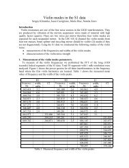
was 125 KS/s for all scans. 30 sequential scans were performed and recorded. Measured<br />
distances minus their average value are plotted versus number of measurements<br />
(N meas ) per scan in Fig. 2. It can be seen that the distance errors decrease with an<br />
increase of N meas . If N meas = 1200, the standard deviation (RMS) of absolute distance<br />
measurements for 30 scans is 49 nm. The average value of measured distances is<br />
706451.585 µm. The relative standard deviation is ∆R/R meas = 7.0 ×10 −8 or 70 ppb.<br />
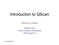
Using the 2nd multi-distance-measurement technique, we extracted the amplitude<br />
and frequency of the dominant vibration. A typical N meas = 200 from one scan is<br />
shown in Fig. 3, in which every 4 adjacent distance measurements are averaged.<br />
The fitted (χ 2 minimization) amplitude and frequency of the vibration were A vib =<br />
0.28 ± 0.08 µm and f vib = 2.97 ± 0.16 Hz, respectively with χ 2 /n.d.f. = 22/46.<br />
Subsequent investigation with a CCD camera trained on the laser output revealed<br />
that the apparent 3 Hz vibration arose from the beam’s centroid motion during the<br />
scan. In addition, we observed a highly reproducible 4 micron drift in measured OPD<br />
within each 20-second scan, also correlated with independently measured beam centroid<br />
drift. Because both of these effects were highly reproducible, arising we believe,<br />
from motion of the internal hinged mirror in the laser used to scan its frequency, interscan<br />
distance measurements proved highly stable, as described above. In a follow-on<br />
demonstration interferometer based on optical fiber transport from the laser to the<br />
beamsplitter (to be described in a subsequent article), we observed strong suppression<br />
of the effects of beam centroid motion, as expected. We conclude that the resulting<br />
ambiguity in distance definition from beam motion on the beam splitter prevents<br />
an absolute distance determination for air transport of the beam, but that timedependent<br />
differential distance change can be accurately determined, even with air<br />
transport.<br />
5. Error Estimations<br />
Some major error sources are estimated in the following;<br />
1) Error from uncertainties of fringe and scanned frequency determination. From<br />
Eq. (2) , the measurement <strong>precision</strong> of R (the error due to the air refractive index<br />
uncertainty is considered separately below) is given by (σ R /R) 2 = (σ ∆N /∆N) 2 +<br />
(σ ∆ν /∆ν) 2 . For a typical scanning rate of 0.5 nm/s with 10 nm scan range, the full scan<br />
time is 20 seconds. The total number of samples for one scan is 2.5 MS if the sampling<br />
rate is 125 KS/s. There is about 3-sample ambiguity for fringe peak and valley position<br />
due to a vanishing slope and the limitation of the 12-bit sampling <strong>precision</strong>. However,<br />
there is a much smaller uncertainty for the Fabry Perot interferometer frequencypeaks<br />
because of their sharpness. Thus, the estimated uncertainty is σ R /R ∼ 1.27 ppm. If<br />
N meas = 1200, the corresponding Ω ∗ ∼ 94, σ R /R ∼ 1.27 ppm × Ω ∗ /Ω/1200 1/2 ∼<br />
51 ppb.<br />
2) Error from vibrations. The detected amplitude and frequency for vibration<br />
are about 0.28 µm and 3.0 Hz. The corresponding time for N meas = 1200 sequential<br />
measurements is 5.3 seconds. A rough estimation of the resulting error gives σ R /R ∼<br />
13 ppb.<br />
4
3) Error from thermal drift. The refractive index of air depends on air temperature,<br />
humidity and pressure etc. Temperature fluctuations are well controlled down to<br />
about 0.5 mK (RMS) in our laboratory by the plastic box on the optical table and the<br />
PVC pipes shielding the volume of air near the laser beam. For a room temperature<br />
of 21 0 C, an air temperature change of 1 0 C will result in a 0.9 ppm change of air<br />
refractive index. 5 For a temperature variation of 0.5 mK in the pipe, N meas = 1200,<br />
the estimated error will be σ R /R ∼ 0.9 ppm/K × 0.5 mK × Ω ∗ ∼ 42 ppb.<br />
4) The air humidity variation is about 0.1% in 3 minutes, it’s expected to be<br />
smaller during one scan (20 seconds). The relative error of distance ∼ 10 ppb. Expected<br />
fluctuations in barometric pressure should have negligible effect on distance<br />
measurements.<br />
The total relative error from the above sources, when added in quadrature, is<br />
∼ 68 ppb, with the major error sources arising from the uncertainty of fringe determination<br />
and the thermal drift. The estimated relative error agrees well with measured<br />
relative errors of 70 ppb from real data.<br />
Besides the above error sources, other sources can contribute to systematic bias<br />
in the absolute differential distance measurement. The major systematic bias comes<br />
from uncertainty of the Free Spectral Range (FSR) of the Fabry Perot interferometer<br />
used to determine scanned frequency range precisely, the relative error would be<br />
σ R /R ∼ 50 ppb if the FSR was calibrated by an wavemeter with a <strong>precision</strong> of<br />
50 ppb. A wavemeter ofthis <strong>precision</strong> was not available for the measurements described<br />
here. Systematic bias from uncertainties of temperature, air humidity and barometric<br />
pressure scales should have negligible effect.<br />
6. Conclusion<br />
A simple demonstration system of a frequency scanned interferometer was constructed<br />
to make high-<strong>precision</strong> absolute differential distance measurements. An accuracy of<br />
50 nm for a distance of approximately 0.7 meters under laboratory conditions was<br />
achieved. Two new multi-distance-measurement analysis techniques were presented<br />
to improve absolute distance measurement and to extract the amplitude and frequency<br />
of vibrations. Major error sources were estimated, and the observed distance<br />
measurement variations were found to be in good agreement with expectation.<br />
Acknowledgments: This work is supported by the National Science Foundation of<br />
the United States under grant PHY-9984997.<br />
References<br />
1. A.F.Fox-Murphy et al., Nucl. Inst. Meth. A383, 229(1996)<br />
2. T. Abe et al., hep-ex/0106058, SLAC-R-570 401(2001)<br />
3. Dai Xiaoli and Seta Katuo, Meas. Sci. Technol.9, 1031(1998)<br />
4. Jack A. Stone et al., Appl. Opt. Vol. 38, No. 28, 5981(1999)<br />
5. B. Edlen, Metrologia 2, 71(1966)<br />
5
Laser<br />
3∼4 mW<br />
665-675 nm<br />
70%<br />
Plane Mirror<br />
50% Retroreflector<br />
Amplified Si Photodetector<br />
PCI-GPIB<br />
Controller<br />
Fabry Perot Interferometer<br />
Computer<br />
PCI Module(DAQ)<br />
BNC Connector<br />
Fig. 1. Schematic of one FSI system.<br />
<strong>Measurement</strong> Residual (µm)<br />
1<br />
0.8<br />
0.6<br />
0.4<br />
0.2<br />
0<br />
-0.2<br />
-0.4<br />
-0.6<br />
-0.8<br />
-1<br />
L meas<br />
= 706451.585 µm<br />
0 200 400 600 800 1000 1200<br />
No. of <strong>Measurement</strong>s / Scan<br />
Fig. 2. The measurement residual spread of 30 sequential scans performed<br />
versus number of measurements/scan.<br />
6
<strong>Measurement</strong> Residual (µm)<br />
1<br />
0.8<br />
0.6<br />
0.4<br />
0.2<br />
0<br />
-0.2<br />
-0.4<br />
-0.6<br />
ID 100<br />
21.54 / 46<br />
P1 0.2412E-01 0.5565E-01<br />
P2 2.972 0.1645<br />
P3 0.2782 0.7842E-01<br />
P4 0.4645 0.5407<br />
5 10 15 20 25 30 35 40 45 50<br />
No. of <strong>Measurement</strong>s<br />
Fig. 3. Typical distribution of measurement residual. The fitted amplitude and<br />
frequency of vibration are A vib = 0.28 ± 0.08 µm and f vib = 2.97 ± 0.16 Hz<br />
respectively.<br />
7