Revolution Installation Manual - RE Prescott Company
Revolution Installation Manual - RE Prescott Company
Revolution Installation Manual - RE Prescott Company

You also want an ePaper? Increase the reach of your titles
YUMPU automatically turns print PDFs into web optimized ePapers that Google loves.
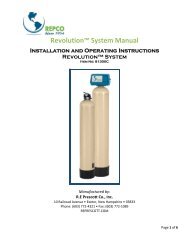
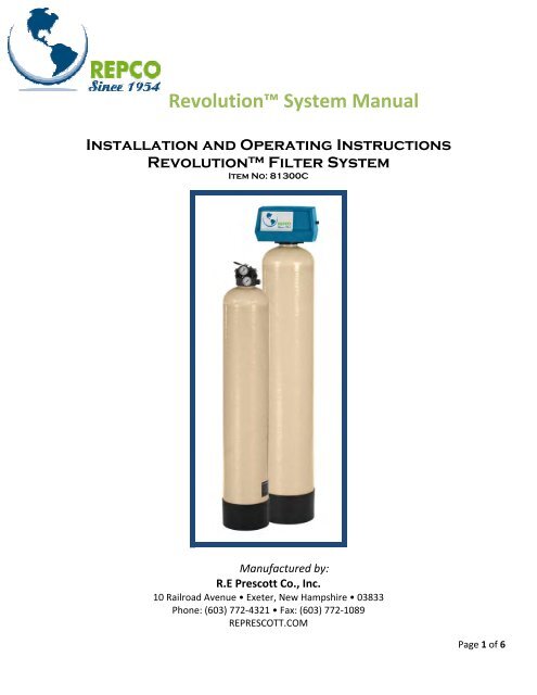
<strong>Revolution</strong> System <strong>Manual</strong><br />
<strong>Installation</strong> and Operating Instructions<br />
<strong>Revolution</strong> Filter System<br />
Item No: 81300C<br />
Manufactured by:<br />
R.E <strong>Prescott</strong> Co., Inc.<br />
10 Railroad Avenue • Exeter, New Hampshire • 03833<br />
Phone: (603) 772‐4321 • Fax: (603) 772‐1089<br />
<strong>RE</strong>P<strong>RE</strong>SCOTT.COM<br />
Page 1 of 6
<strong>Revolution</strong>® System<br />
The <strong>Revolution</strong> TM System includes a deluxe aeration tank along with a <strong>RE</strong>PCO Conditioner filter. The deluxe aeration<br />
tank it is built around a PVC head incorporating a built‐in micronizer (nozzle and venturi), internal air release float, and<br />
instrumentation, all in one package. The pressure gauges allow the installer to make adjustments to suit the best air<br />
draw, and a bypass allows for ease of service.<br />
<strong>Revolution</strong> System Application<br />
1. The <strong>Revolution</strong> TM is designed to work with submersible well pump installations operated by a pressure switch<br />
and pressure tank.<br />
2. The <strong>Revolution</strong> TM is not designed to work with jet pump systems or constant pressure systems<br />
3. The <strong>Revolution</strong> TM should be installed in accordance with applicable state and local plumbing codes.<br />
<strong>Revolution</strong> Aeration Tank Head<br />
<strong>Revolution</strong> Aeration Tank<br />
Figure 1 ‐ <strong>Revolution</strong> Aeration Tank<br />
Page 2 of 6
<strong>Revolution</strong>® System<br />
Assembly<br />
Assembling the <strong>Revolution</strong> Aeration Tank<br />
The <strong>Revolution</strong> Aeration Tank comes preassembled as seen in Figures 1 through 3.<br />
Figure 2 – <strong>Revolution</strong> Aeration Tank Head<br />
Figure 3 – <strong>Revolution</strong> Aeration Tank Head<br />
Page 3 of 6
<strong>Revolution</strong>® System<br />
Assembling the <strong>RE</strong>PCO Conditioner Filter<br />
The <strong>RE</strong>PCO Conditioner Filter should come preassembled. If not, filter media needs to be installed; follow instructions<br />
below.<br />
1. Remove Automatic Backwashing Valve from the top of empty mineral tank.<br />
2. Plug the top of the distributor tube so that no mineral falls down the tube during filling.<br />
3. Add specified amount of gravel to the bottom of the mineral tank so that the base of the distributor tube is<br />
sufficiently covered.<br />
4. Pour media into the tank until it reaches 18” from the top of the mineral tank.<br />
5. Remove the plug from distributor tube.<br />
6. Reinstall the Automatic Backwashing Valve to the top of the mineral tank. Be careful not to disturb the o‐ring<br />
that is located in the distributor tube opening and also on the flange that meets the top of the mineral tank.<br />
Leaks could result.<br />
<strong>Installation</strong> / Start Up<br />
<strong>Installation</strong><br />
Set units into their final position and plumb in accordance with applicable state and local plumbing codes. Refer to<br />
appropriate control valve manual for inlet/outlet plumbing, drain line positioning, fitting assembly, power supply, and<br />
start up of control valve.<br />
<strong>Revolution</strong> Aeration Tank<br />
1. With a screw driver, manually unscrew the brass bypass screw counterclockwise to open the bypass port. Refer<br />
to figure 3. This will keep initial inlet pressure to a minimum. Do not exceed 100 PSI inlet pressure. The inlet<br />
pressure gauge is the bottom gauge. Refer to figure 2.<br />
2. Turn on power to well pump and manually adjust brass bypass screw to the desired air draw. Refer to air draw<br />
charts below.<br />
3. Shine a light behind mineral tank to confirm water level is consistently 14 to 18” below top of tank.<br />
Automatic Backwashing Valve<br />
Refer to Automatic Backwashing Valve <strong>Manual</strong> for <strong>Installation</strong>/Startup Instructions<br />
Page 4 of 6
<strong>Revolution</strong>® System<br />
<strong>RE</strong>PCO Conditioner Filter<br />
<strong>Revolution</strong> Aeration Tank<br />
Pressure Tank (Not Included)<br />
Figure 4 ‐ <strong>Revolution</strong> System<br />
Operation<br />
<strong>Revolution</strong> Aeration Tank<br />
1. When the well pump is filling the <strong>Revolution</strong> TM the nozzle and venturi draws air into the mineral tank as air draw<br />
charts indicate.<br />
2. As the air is drawn into the mineral tank, the water level drops to approximately 14” below top of mineral tank<br />
and the air release float assembly opens allowing excess air to be released through the air release connection.<br />
Refer to figure 2.<br />
3. As the air is released from the mineral tank the water level raises to approximately 10” below the top of the<br />
mineral tank and the air release float assembly closes.<br />
<strong>Revolution</strong> Aeration Tank Air Draw Charts<br />
5 GPM flow<br />
CFH air draw<br />
Inlet Pressure<br />
Gauge<br />
Outlet Pressure<br />
Gauge<br />
6.5 80 30<br />
4.5 80 40<br />
2.5 80 50<br />
Stops draw 80 52<br />
Figure 5 – 5 GPM Flow<br />
Page 5 of 6
<strong>Revolution</strong>® System<br />
7.5 GPM flow<br />
CFH air draw<br />
Inlet Pressure<br />
Gauge<br />
6.5 80 30<br />
4.0 80 40<br />
.75 80 50<br />
Stops draw 80 53<br />
Figure 6 – 7.5 GPM Flow<br />
10 GPM flow<br />
CFH air draw<br />
Outlet Pressure<br />
Gauge<br />
Inlet Pressure<br />
Gauge<br />
12.5 80 30<br />
11 80 40<br />
8 80 50<br />
Stops draw 80 52<br />
Figure 7 – 10 GPM Flow<br />
15 GPM flow<br />
CFH air draw<br />
Outlet Pressure<br />
Gauge<br />
Inlet Pressure<br />
Gauge<br />
9 80 30<br />
6 80 40<br />
1 80 50<br />
Stops draw 80 54<br />
Figure 8 – 15 GPM Flow<br />
Automatic Backwashing Valve<br />
Refer to Automatic Backwashing Valve <strong>Manual</strong> for Operation.<br />
Outlet Pressure<br />
Gauge<br />
Page 6 of 6