The Commercial Bubble-Up CBU-415 - RE Prescott Company
The Commercial Bubble-Up CBU-415 - RE Prescott Company
The Commercial Bubble-Up CBU-415 - RE Prescott Company

You also want an ePaper? Increase the reach of your titles
YUMPU automatically turns print PDFs into web optimized ePapers that Google loves.
High Flow Radon Problems ?<br />
We have a patented natural solution.<br />
At last, an answer to your high flow rate, radon<br />
plagued, community water supplies.<br />
INTRODUCING THE COMMERCIAL <strong>Bubble</strong>-<strong>Up</strong><br />
®<br />
MADE IN<br />
R.E. P<strong>RE</strong>SCOTT CO., INC.<br />
THE USA
Radon is a serious concern for many people with well water. Radon gas has<br />
been associated with causing cancer. <strong>The</strong> government now recommends<br />
removing as much radon from your water as possible. <strong>The</strong> <strong>Commercial</strong><br />
<strong>Bubble</strong>-<strong>Up</strong> makes this possible. Removing your concern!<br />
62<br />
INCHES<br />
30<br />
INCHES<br />
9”<br />
<strong>Bubble</strong><br />
Chamber<br />
9”<br />
<strong>Bubble</strong><br />
Chamber<br />
WELL RAW<br />
WATER SUPPLY<br />
9”<br />
<strong>Bubble</strong><br />
Chamber<br />
9”<br />
<strong>Bubble</strong><br />
Chamber<br />
BLOWER PLUG BOX<br />
AIR BLOWERS (QTY 4)<br />
ACCESS COVER<br />
HIGH WATER ALARM<br />
WELL PUMP CUT OUT<br />
WELL PUMP OFF<br />
WELL PUMP ON<br />
LOW WATER ALARM<br />
TRANSFER PUMP CUT OUT<br />
3” AIR EXHAUST VENT<br />
ACCESS<br />
COVER<br />
2” OVERFLOW<br />
ELECTRICAL JUNCTION BOX<br />
3” AIR EXHAUST VENT<br />
61<br />
INCHES<br />
2” OVERFLOW<br />
TO<br />
WATER<br />
SYSTEM<br />
ELECTRICAL JUNCTION BOX<br />
<strong>Bubble</strong>-<strong>Up</strong> ® is a trademark of the<br />
R.E. <strong>Prescott</strong> Co., Inc. Exeter, NH 03833<br />
www.represcott.com<br />
Call for Sales and Service:<br />
CONTROL<br />
PANEL<br />
CONTROL<br />
PANEL<br />
Pump Skid<br />
01/05<br />
Features and Benefits<br />
COMPACT SIZE<br />
· <strong>The</strong> commercial <strong>Bubble</strong>-<strong>Up</strong>® is compact<br />
· Saves valuable floor space<br />
· Uses half the space of other brands<br />
· Unit mounted blowers<br />
· <strong>Commercial</strong> <strong>Bubble</strong>-<strong>Up</strong>® measurements<br />
30" wide x 61" deep x 62" tall<br />
· Quiet operation<br />
· Extra insulated blowers<br />
· Quiet transfer pump<br />
SAFETY FEATU<strong>RE</strong>S<br />
· Overflow relief valve<br />
· High level well pump shutdown<br />
· High level alarm<br />
· Run dry transfer pump protection<br />
· Low level alarm<br />
SIMPLE INSTALLATION<br />
· Pipe the inlet<br />
· Pipe the outlet<br />
· Pipe the vent exhaust<br />
· Wire the controls<br />
· Power the panel<br />
MODULAR CONSTRUCTION<br />
· Simple assembly of components for ease<br />
of maintenance and service<br />
HIGHEST QUALITY PARTS<br />
· 2" Bronze ball valve for raw water in/out<br />
· Stainless hardware<br />
· 3" Air connection exhaust outlet<br />
· Heavy duty poly <strong>Bubble</strong>-<strong>Up</strong>® tank<br />
· 9” Reactor vessel<br />
· NSF approved poly.<br />
OUTPUT: HIGH P<strong>RE</strong>SSU<strong>RE</strong> AND HIGH FLOW<br />
INPUT: HIGH EFFICIENCY<br />
· 99+% Removal<br />
· See test results at www.represcott.com<br />
<strong>Bubble</strong>-<strong>Up</strong>® Simple Installation<br />
PIPE IN & OUT and POWER THE PANEL:<br />
2 - 2" NPT water connections<br />
1 - 3" PVC air outlet connection<br />
1 - 2" NPT Overflow<br />
230 volt, 50 AMP Electrical
COMMERCIAL BUBBLE-UP SPECIFICATIONS<br />
Design Flow Rate:<br />
<strong>The</strong> water system flow rate for the <strong>Commercial</strong> <strong>Bubble</strong>-<strong>Up</strong> Unit is 50 gpm.<br />
Radon Removal:<br />
<strong>The</strong> <strong>Commercial</strong> <strong>Bubble</strong>-<strong>Up</strong> (<strong>CBU</strong>) system is furnished with one <strong>415</strong> gallon storage compartment<br />
and four (4), bubbling chambers. <strong>The</strong> well pump flows water to the inlet manifolds where it mixes<br />
with the air at the top of each bubbling chamber. <strong>The</strong>se chambers over flow into the storage<br />
compartment and is pumped to the distribution system with a transfer pump.<br />
<strong>The</strong> <strong>CBU</strong> is supplied as a packaged, fully assembled, skid-mounted Radon <strong>Bubble</strong><strong>Up</strong> system.<br />
Components include One (1) <strong>415</strong> gallon storage tank, four (4) 9 inch diameter 12 gpm bubbling<br />
chambers, blowers, NEMA 12 UL-508 control panel with alarms, and 3 HP, single phase, 50 GPM<br />
transfer pump. <strong>The</strong> transfer pump is controlled by the pressure of the distribution system.<br />
Radon removed with the <strong>CBU</strong> will be vented to atmosphere through a 3 inch vent outside the<br />
building wall or roof.<br />
Equipment:<br />
<strong>CBU</strong> System:<br />
One (1) Radon <strong>Bubble</strong>UP model <strong>CBU</strong><strong>415</strong>-3HP/230V/1P a packaged skid-mounted radon removal<br />
system. <strong>The</strong> <strong>CBU</strong> comes complete with blower, NEMA 12 control panel, and one (1) F&W model<br />
C22231 centrifugal pump rated for 50 gpm at 140 ft. TDH (60 PSI). <strong>The</strong> aeration system is a<br />
complete package, including controls and repumping. <strong>The</strong> <strong>CBU</strong> system uses the patented concurrent<br />
flow aeration method.<br />
<strong>The</strong> <strong>CBU</strong> is constructed with molded plastic storage compartment. <strong>The</strong> bubbling chambers are<br />
polyethylene and are completely removable from the storage compartments. <strong>The</strong> lids shall be<br />
fastened to storage compartment with stainless steel hardware. <strong>The</strong> lids have a gasket seal. <strong>The</strong><br />
<strong>CBU</strong>-<strong>415</strong> has one storage compartments with 4, 9” bubbling chambers. <strong>The</strong> inlet manifolds are<br />
constructed from PCV. Blowers are unit mounted and are provided. All fittings will be union<br />
disconnect fittings for a completely removable and serviceable system.<br />
All water, air, and vent connections to the vessel shall be Sch 40 PVC or brass construction. Fittings<br />
and pipe sizes are sized for proper head loss. <strong>The</strong> <strong>CBU</strong> will be equipped with a 2” drain fitting,<br />
isolation ball valves and unions.<br />
<strong>The</strong> NEMA 12 control panel (UL-508 listed) includes IEC-type motor starters w/overload protection<br />
for the transfer pump. <strong>The</strong> transfer pump will be controlled by a system pressure switch with low<br />
water cut-off. <strong>The</strong> panel will have system alarms with dry contacts for external notification devices<br />
(by others). Alarms will be low water level and high water level. On high water level there will be a<br />
redundant well pump shut off. <strong>The</strong> control panel includes HOA switches; elapse time meters, run<br />
lights for each motor and a Test-Auto-Reset alarm switch.<br />
= END =
A B C D E F G H<br />
50 GPM <strong>Bubble</strong><strong>Up</strong> Unit<br />
AIR BLOWERS (QTY 4)<br />
ACCESS COVER<br />
3” AIR EXHAUST VENT<br />
ELECTRICAL JUNCTION BOX<br />
-000<br />
-010<br />
-020<br />
-030<br />
-040<br />
-050<br />
-060<br />
HIGH WATER ALARM<br />
WELL PUMP CUT OUT<br />
-070<br />
62<br />
INCHES<br />
CONTROL<br />
PANEL<br />
WELL PUMP OFF<br />
WELL PUMP ON<br />
-080<br />
-090<br />
-100<br />
-110<br />
-120<br />
-130<br />
LOW WATER ALARM<br />
TRANSFER PUMP CUT OUT<br />
-140<br />
TO<br />
WATER<br />
SYSTEM<br />
WELL RAW<br />
WATER SUPPLY<br />
61<br />
INCHES<br />
3” AIR EXHAUST VENT<br />
-150<br />
-160<br />
-170<br />
-180<br />
30<br />
INCHES<br />
9”<br />
<strong>Bubble</strong><br />
Chamber<br />
9”<br />
<strong>Bubble</strong><br />
Chamber<br />
9”<br />
<strong>Bubble</strong><br />
Chamber<br />
9”<br />
<strong>Bubble</strong><br />
Chamber<br />
ACCESS<br />
COVER<br />
ELECTRICAL JUNCTION BOX<br />
-190<br />
-200<br />
-210<br />
-220<br />
-230<br />
CONTROL<br />
PANEL<br />
-240<br />
Pump Skid<br />
-250<br />
COMMERCIAL BUBBLEUP UNIT<br />
MODEL <strong>CBU</strong><strong>415</strong>-3HP/230V/1P<br />
R.E. P<strong>RE</strong>SCOTT CO., INC.<br />
10 RAILROAD AVENUE<br />
EXETER, NH 03833
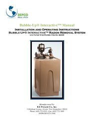
OPERATING INSTRUCTIONS<br />
<strong>Commercial</strong> <strong>Bubble</strong>-<strong>Up</strong> Radon Removal Unit<br />
Dear Radon Professional,<br />
Congratulations on purchasing this high-quality <strong>RE</strong>PCO<br />
CONDITIONER product.<br />
P<strong>RE</strong>CAUTIONS:<br />
Before putting your <strong>Bubble</strong>-<strong>Up</strong> into operation, thoroughly read and<br />
follow these instructions. This will make you familiar with the<br />
product and its operation. We also recommend reading the operating<br />
instructions for the pump, float switches and blowers.<br />
SAFETY RULES:<br />
For safety reasons, the <strong>Bubble</strong>-<strong>Up</strong> is not meant to be used by people<br />
who have not previously read these instructions. This applies in<br />
particular to children and young people under 16, who must be kept<br />
away from the product when it is in operation.<br />
Ensure that all electrical connections are located in places that are not<br />
reachable by water.<br />
Blowers are to be mounted above the <strong>Bubble</strong>-<strong>Up</strong>.<br />
Before using the product, make sure that the main voltage corresponds<br />
to the voltage indicated on the data plate of the <strong>RE</strong>PCO Control.<br />
(230 volts, single phase).<br />
Conformity with local and State electric codes is mandatory. <strong>The</strong><br />
National Electric Code requires that a ground fault circuit interrupter<br />
(GFCI) be used in the branch circuit supplying pumps. Consult a<br />
licensed electrician or your power company if in doubt.<br />
WARNING:<br />
Operating range:<br />
ON: pressure = (30 PSI)<br />
OFF: pressure = (50 PSI)<br />
Specifications:<br />
Power source (Transfer Pump max. power): 16A - 230V - 60Hz<br />
Max delivery (60 GPM.)<br />
Max water temperature: 35 C<br />
Max. operating pressure (110 PSI.)<br />
<strong>RE</strong>PCO CONTROLS AND PROTECTION SYSTEM<br />
<strong>The</strong> <strong>RE</strong>PCO Controls convert the electric transfer pump and well<br />
pump into an automatically operating radon removal system for<br />
commercial use. <strong>The</strong> controls operates and performs four functions:<br />
1. It allows for transfer pump operation:<br />
It starts the tranfer pump when the pressure in the system drops to the<br />
ON pressure. <strong>The</strong> transfer pump stops when the system pressure<br />
reaches the OFF pressure. <strong>The</strong> existing system pressure switch is<br />
connected to terminals 4 & 5 in the <strong>RE</strong>PCO Controls.<br />
2. It protects the tranfer pump from dry operation:<br />
<strong>Bubble</strong>-<strong>Up</strong> Operating Instructions<br />
Page 1/3
<strong>The</strong> specially designed safety device automatically stops the transfer<br />
pump when water is low in the <strong>415</strong> gallon <strong>Bubble</strong>-<strong>Up</strong> tank, thus<br />
preventing possible damage due to the transfer pump running dry. <strong>The</strong><br />
stopping action is accomplished by the low water cut off float. This<br />
float closes on an empty tank stopping the transfer pump and alarming<br />
by the red alarm light and buzzer on the <strong>RE</strong>PCO Controls. This<br />
informs the user of the low water condition. <strong>The</strong>re are additional dry<br />
contacts, terminals 12 & 13, for remote alarm indication.<br />
3. It allows for well pump and blower operation:<br />
It starts the well pump and blowers when the level in the <strong>Bubble</strong>-<strong>Up</strong><br />
tank drops the ON float. <strong>The</strong> well pump and blowers run and stop<br />
when the level in the tank reaches the OFF float.<br />
4. It protects the well pump from overflow:<br />
<strong>The</strong> specially designed safety device automatically stops the well<br />
pump when high water is in the <strong>415</strong> gallon <strong>Bubble</strong>-<strong>Up</strong> tank, thus<br />
preventing possible damage due to flooding. <strong>The</strong> stopping action is<br />
accomplished by the high water float. This float closes on an over full<br />
tank stopping the well pump and alarming by the red alarm light and<br />
buzzer on the <strong>RE</strong>PCO Controls. This informs the user of the high<br />
water condition. <strong>The</strong>re are additional dry contacts, terminals 10 & 11,<br />
for remote alarm indication.<br />
FUNCTIONAL PARTS<br />
l. 2 inch inlet header valve.<br />
2. 1 inch inlet supplies.<br />
3. 1st stage treatment manifold<br />
4. Blower and inlet tee.<br />
5. Reactor tank.<br />
6. Concurrent aeration grids.<br />
<strong>Bubble</strong>-<strong>Up</strong> Operating Instructions<br />
Page 2/3<br />
7. Transfer pump.<br />
8. Well pump and blower, transfer pump and alarm float control<br />
switches.<br />
9. <strong>RE</strong>PCO Controls operating panel.<br />
10. Air exhaust connection.<br />
11. 2 inch drain connection.<br />
12. 2 inch overflow connection<br />
ELECTRICAL/MECHANICAL CONNECTION<br />
<strong>The</strong> <strong>Bubble</strong>-<strong>Up</strong> is provided with a <strong>RE</strong>PCO Controls panel. All<br />
connecting cables, power supply and pump connections are done on<br />
the terminal strip in the control panel.<br />
1) Connecting cables are included for the floats; connect them to the<br />
proper terminals. Connect the well pump and transfer pump to the<br />
<strong>RE</strong>PCO Controls. Connect the blowers and plug them into the<br />
separate quadplex outlet provided. Connect the system pressure<br />
switch to the controls.<br />
2) Cut into the existing plumbing of the water system and install a<br />
bypass valve set-up. Connect the inlet bypass so that the raw water of<br />
the existing system is going to the 2 inch inlet header valve. Connect<br />
the outlet bypass valve back to the transfer pump discharge so that the<br />
treated water from the <strong>Bubble</strong>-<strong>Up</strong> goes to the system.<br />
3) Connect the blowers to the inlet tee. Mount the blower above the<br />
<strong>Bubble</strong>-<strong>Up</strong>. Pipe the air exhaust outside and terminate 2 feet above<br />
the eaves of the home and away from any windows.<br />
4) Pipe the overflow to a gravity floor drain. Do not pipe more that 10<br />
inches above the <strong>Bubble</strong>-<strong>Up</strong> or it will not drain properly and the<br />
potential for flooding and over flow exists.<br />
PUTTING THE <strong>Bubble</strong>-<strong>Up</strong> INTO OPERATION
WARNING: BEFO<strong>RE</strong> PUTTING THE SYSTEM INTO<br />
OPERATION, FILL THE BUBBLE-UP TANK AND TRANSFER<br />
PUMP WITH WATER TO PRIME. AIR MUST BE VENTED<br />
FROM THE TRANSFER PUMP. THIS IS NECESSARY TO<br />
ALLOW THE TRANSFER PUMP TO BE FILLED WITH<br />
WATER WHEN IT IS FIRST USED AND TO P<strong>RE</strong>VENT<br />
DAMAGE.<br />
Place the <strong>RE</strong>PCO Controls circuit breakers and HOA selector switches<br />
in the OFF position. Power the <strong>RE</strong>PCO Controls panel with a separate<br />
230 volt single phase power supply.<br />
Start the well pump by operating the HOA selector switch in the<br />
HAND position. Run the well pump and check that the operation of<br />
the blowers. After operation is correct place the selctor in the AUTO<br />
position and allow the well pump to run until it shuts off<br />
automatically.<br />
Prime the transfer pump, after it is fully primed run the transfer pump<br />
in HAND until there is pressure in the system. Place the selector in<br />
AUTO and alloe the transfer pump to run until it stops automatically.<br />
<strong>The</strong> system is now operational. Leave the selector switches in AUTO.<br />
Never leave the selectors in HAND un-attended as the pumps will not<br />
stop automatically. <strong>The</strong> HAND position is for the trained operator to<br />
trouble shoot or test the operatiuon of the system.<br />
follow the instructions imparted by the various component<br />
manufacturers.<br />
<strong>The</strong> warranty will be regarded as null and void if the plug or power<br />
cords have been altered or tampered with or if transfer pump, float<br />
switch or blowers has been partly or totally disassembled.<br />
For information on operating troubles, carefully read the operating<br />
instructions of the related pump.<br />
We expressly state that, in conformity with the legislation in force, no<br />
responsibility is assumed for damage caused by our products through<br />
improper installation, use or repairing techniques or due to use of nongenuine<br />
spare parts or of components not approved by<br />
R.E. <strong>Prescott</strong> Co., Inc. or, at all events, resulting from repairs not<br />
carried out at an authorized service center or by authorized skilled<br />
personnel. <strong>The</strong> same applies to attachments and accessories.<br />
R.E. <strong>Prescott</strong> Co., Inc.<br />
10 Railroad Ave<br />
Exeter, NH 03833<br />
CALL FOR LOCAL SERVICE<br />
Draw water in the system to have the <strong>Bubble</strong>-<strong>Up</strong> cycle, check for leaks<br />
and correct operation.<br />
WARRANTY<br />
<strong>The</strong> warranty is valid for a period of 12 months from the date of<br />
purchase solely for defects in materials or workmanship. <strong>The</strong><br />
warranty does not cover malfunctions due to misuse or to failure to<br />
<strong>Bubble</strong>-<strong>Up</strong> Operating Instructions<br />
Page 3/3