POLYAIR INSTALLATION INSTRUCTIONS - Airsprings.cc
POLYAIR INSTALLATION INSTRUCTIONS - Airsprings.cc
POLYAIR INSTALLATION INSTRUCTIONS - Airsprings.cc

Create successful ePaper yourself
Turn your PDF publications into a flip-book with our unique Google optimized e-Paper software.
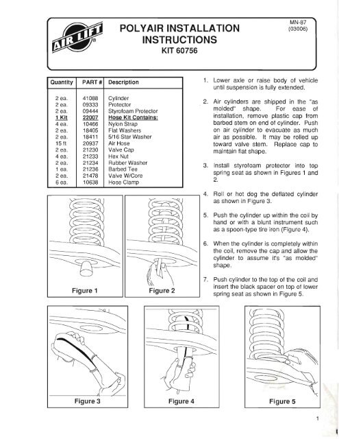
Quantity PART # Description<br />
2 ea. 41088 Cylinder<br />
2 ea. 09333 Protector<br />
2 ea. 09444 Styrofoam Protector<br />
1 Kit 22007 Hose Kit Contains:<br />
4 ea. 10466 Nylon Strap<br />
2 ea. 18405 Flat Washers<br />
2 ea. 18411 5/16 Star Washer<br />
15 ft 20937 Air Hose<br />
2 ea. 21230 Valve Cap<br />
4 ea. 21233 Hex l\Jut<br />
2 ea. 21234 Rubber Washer<br />
1 ea. 21236 Barbed Tee<br />
2 ea. 21478 Valve W/Core<br />
6 ea. 10638 Hose Clamp<br />
<strong>POLYAIR</strong> <strong>INSTALLATION</strong><br />
<strong>INSTRUCTIONS</strong><br />
KIT 60756<br />
MN-87<br />
(03006)<br />
1. Lower axle or raise body of vehicle<br />
until suspension is fully extended.<br />
2. Air cylinders are shipped in the "as<br />
molded" shape. For ease of<br />
installation, remove plastic cap from<br />
barbed stem on end of cylinder. Push<br />
on air cylinder to evacuate as much<br />
air as possible. It may be rolled up<br />
toward valve stem. Replace cap to<br />
maintain flat shape.<br />
3. Install styrofoam protector into top<br />
spring seat as shown in Figures 1 and<br />
2.<br />
r-----------,,-------------, 4. Roll or hot dog the deflated cylinder<br />
as shown in Figure 3.<br />
Figure 1 Figure 2<br />
5. Push the cylinder up within the coil by<br />
hand or with a blunt instrument such<br />
as a spoon-type tire iron (Figure 4).<br />
6. When the cylinder is completely within<br />
the coil, remove the cap and allow the<br />
cylinder to assume it's "as molded"<br />
shape.<br />
7. Push cylinder to the top of the coil and<br />
insert the black spacer on top of lower<br />
spring seat as shown in Figure 5.<br />
Figure 3 Figure 4 Figure 5<br />
1
Use this procedure for all hose connections:<br />
A. Slide a hose clamp onto the tubing.<br />
B. Push the tubing over the barbed stem.<br />
C. Compress the ears on the hose clamp<br />
with pliers and slide it forward to fully<br />
cover the barbed section.<br />
Figure 6<br />
Figure 7<br />
l<br />
:'..<br />
Figure 8<br />
TEE HOSE ROUTING<br />
A. Locate desired "tee" location on the frame<br />
rail or cross member.<br />
B. Determine and cut adequate length of<br />
tubing to reach from tee to left and right<br />
side on air cylinders.<br />
CAUTION: LEAVE SUFFICIENT HOSE<br />
SLACK TO PREVENT ANY STRAIN ON<br />
FITTINGS DURING AXLE MOTIONS.<br />
C. Slide a hose clamp onto the tubing.<br />
D. Push the tubing over one side of the "tee"<br />
until all the barbs are covered. Repeat<br />
procedure for other leg of tee (Figure 6).<br />
E. With pliers slide the hose clamp forward<br />
until it fully covers the barbed section.<br />
Repeat for the other leg of tee (Figure 6).<br />
F. Route tubing along cross member and<br />
either lower control arm or upper spring<br />
seat to left and right air cylinder (Figure 7).<br />
G. Insert tubing through spring seat, spacer<br />
and slide on a hose clamp.<br />
H. Push the tubing onto the stem, covering all<br />
the barbs (Figure 8).<br />
I. With pliers slide the hose clamp upward<br />
until it fully covers the barbed section.<br />
J. Push the remaining tubing over the last<br />
fitting on tee and route along frame to<br />
desired inflation valve location. Attach<br />
with plastic straps or wire.<br />
TO PREVENT TUBING FROM MELTING,<br />
KEEP IT AT LEAST SIX INCHES FROM<br />
EXHAUST SYSTEM.<br />
K. Select a location for inflation valve in the<br />
gas cap well, trunk, rear bumper, fender<br />
flange or behind the license plate, insuring<br />
that the valve will be protected and<br />
a<strong>cc</strong>essible with air hose (Figures 7, 9).<br />
L. Drill a 5/16" hole for inflation valve and<br />
mount as in illustration (Rubber washer is<br />
for outside weather seal - Figure 9).
Rubber Washer<br />
Figure 9<br />
Figure 10<br />
o<br />
M. Slide a hose clamp over hose. Push<br />
tubing onto fitting covering all barbs. With<br />
pliers slide the hose clamp forward until it<br />
fully covers the barbed section (Figure<br />
10).<br />
N. Raise axle or lower body until air cylinders<br />
lightly touch upper spring seat and lower<br />
spacers.<br />
O. Check TAILPIPE clearance and insure<br />
that it is at least 6 inches from air cylinder.<br />
If necessary, loosen clamps and rotate or<br />
move to obtain additional clearance.<br />
3
4<br />
MAINTENANCE/OPERATION<br />
MINIMUM AIR PRESSURE MAXIMUM AIR PRESSURE<br />
4 PSI 25 PSI<br />
MAINTENANCE TIPS:<br />
1. Check pressure monthly!<br />
2. Always maintain at least 4 psi air pressure to prevent chafing or coil pinch.<br />
3. If you develop an air leak in the system, use a soapy solution to check all hose connections and the valve core<br />
before removing cylinder.<br />
OPERATING TIPS:<br />
1. Inflate you air springs to 25 psi before adding the payload. This will allow the air cylinder to properly mesh with the<br />
coil spring. After vehicle is loaded, adjust your air pressure (down) to level the vehicle and for ride comfort.<br />
2. When you are carrying a payload it will be helpful to increase the tire inflation pressure in proportion to any overload<br />
condition. We recommend a 2 psi increase above normal (not to exceed tire manufacturer's maximum) for each<br />
100 Ibs. total overload on the axle.<br />
Increase you Air Spring's versatility with our easy-to-install Load Controller System<br />
Use with <strong>POLYAIR</strong> SPRINGS or LOADLIFTER 2500 system.<br />
Compressor mounts easily in engine compartment.<br />
Dash-mounted 0 - 100 psi gauge with fill and deflate controls.<br />
Includes complete installation kit: air hose, fittings, hardware, electrical wire, and in-line fuse.<br />
Ask for Part Number 25589 (Suggested Retail $69.95)<br />
Thank you for purchasing Air Lift Products<br />
AIR LIFT COMPANY<br />
P.O. BOX 80167<br />
Lansing, MI 48908-0167<br />
FOR TECHNICAL ASSISTANCE CA 8<br />
CAUTION: DO NOT EXCEED THE VEHICLE MANUFACTURER'S GROSS VEHICLRATING.<br />
<strong>POLYAIR</strong>®<br />
SPRING<br />
T<br />
Prinled in the USA