Programmable Tach with hourmeter - VDO Instruments and ...
Programmable Tach with hourmeter - VDO Instruments and ...
Programmable Tach with hourmeter - VDO Instruments and ...

Create successful ePaper yourself
Turn your PDF publications into a flip-book with our unique Google optimized e-Paper software.
œ<br />
3. Analog (Pointer) Calibration ( )<br />
You can adjust the calibration of the tachometer’s analog<br />
display (the pointer showing revolutions per minute) by<br />
using speed test equipment <strong>and</strong> the “ ” function on<br />
the LCD readout. The pointer can be repositioned anywhere<br />
<strong>with</strong>in the calibration range of the tachometer.<br />
To manually calibrate the pointer on the analog display:<br />
1. Press <strong>and</strong> hold in the button on the tachometer as you<br />
turn on the ignition <strong>and</strong> start the engine. Hold in the<br />
button until the word “ ” shows up. When it does,<br />
release the button. Set the RPM using a reference tachometer<br />
at a value above idle (e.g. 2000 RPM).<br />
2. Press the button once, <strong>and</strong> the word “ ” will be<br />
displayed on the LCD readout. Press it twice rapidly<br />
then release it for a second, <strong>and</strong> the word “ ” will be<br />
displayed. So if you need an upward calibration of the<br />
pointer, press the button once. If you need a downward<br />
calibration, press the button twice rapidly <strong>and</strong> release it.<br />
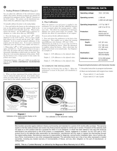
3. When either “ ” or “ ” is showing, press the button<br />
again, <strong>and</strong> hold it in. If you hold the button in for just a<br />
short time, the pointer will move slowly either upwards or<br />
downwards, depending on which mode you selected. This<br />
allows for a very accurate adjustment of the pointer. Holding<br />
the button in for a longer period of time makes the<br />
pointer move faster.<br />
Adjustments between –30% <strong>and</strong> +100% are possible, but<br />
must be done WITH A REFERENCE TACHOMETER<br />
ONLY!!!<br />
It is recommended that these adjustments be done<br />
only by experienced mechanics.<br />
4. When you have repositioned the pointer where you<br />
want it, release the button <strong>and</strong> wait. If no further adjustments<br />
are made <strong>with</strong>in one minute, the tachometer will<br />
revert back to the normal operating mode.<br />
NOTE: If you move the pointer past the upper<br />
limit of the calibration range, the LCD display will<br />
flash <strong>and</strong> you will only be able to adjust the pointer<br />
downward. If you move the pointer past the lower<br />
calibration limit, the LCD display will also flash,<br />
<strong>and</strong> you will only be able to adjust the pointer upward.<br />
4. Fine Calibration<br />
When the ignition is on <strong>and</strong> power is supplied to the<br />
tachometer you can select the fine calibration function<br />
to very accurately adjust the running speed — difference<br />
ratio. This allows for compensation of alternator<br />
slippage over various speed ranges, for example. This<br />
function also allows for syncronization of two engines.<br />
To access <strong>and</strong> use the fine calibration function:<br />
1. Press <strong>and</strong> release the pushbutton on the back of the<br />
tachometer. This enables you to adjust the running<br />
speed/difference ratio between –20% <strong>and</strong> +20%.<br />
Adjustments are made in (+) or (–) steps of 0.5% by<br />
pressing <strong>and</strong> holding the button. When the adjustment<br />
is complete, release the button. After a short time, the<br />
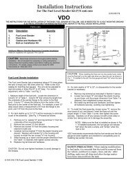
display reverts back to its normal mode. See Diagram J<br />
for examples of:<br />
Display 1: 0.0% difference to the adjusted value;<br />
Display 2: 2.0% difference to the adjusted value;<br />
Display 3: 2.5% difference to the adjusted value.<br />
TO COMPLETE THE INSTALLATION:<br />
Perform Step 4 of Section One on Page 1. When the<br />
tachometer is secure in the panel, your installation is<br />
finished.<br />
Operating voltage:<br />
Operating current:<br />
Operating temperature:<br />
Protection:<br />
Dimensions—<br />
Depth:<br />
Diameter:<br />
Illumination:<br />
TECHNICAL DATA<br />
Calibration range:<br />
10.8 – 32 Volts<br />
< 100 mA<br />
(< 600 mA <strong>with</strong> light)<br />
– 4° F to 158° F<br />
(-20° C to 70° C)<br />
IP65 (Front)<br />
Ozone <strong>and</strong> UV<br />
resistant housing<br />
3.6" (91 mm)<br />
3 ¹⁄₈" (80 mm)<br />
3 ³⁄₈" (85 mm)<br />
4" (100 mm)<br />
Backlit / Frontlit<br />
dial <strong>and</strong> display<br />
0.5 to 200 pulses<br />
per revolution<br />
Programming<strong>Tach</strong>ometers <strong>with</strong> Generator Sender<br />
1. Use pulse instruction to program tachometer.<br />
2. Must use tachometer <strong>with</strong> engine hour meter.<br />
3. If your ratio is 1:1 use 4 pules<br />
If your ratio is 2:1 use 2 pules<br />
GXU^i_ecUU²1TZecd³<br />
@ecX_^SUQ^T²E`³<br />
YcTYc`\QiUT<br />
<strong>VDO</strong><br />
BQ`YT\i`ecXdgYSU<br />
d_cUU²4>³KV_b<br />
T_g^M<br />
<strong>VDO</strong><br />
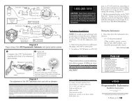
Adjust pointer by pushing<br />
<strong>and</strong> holding in the<br />
button on the<br />
rear of the tachometer<br />
then<br />
or<br />
Example #1<br />
Example #2<br />
Example #3<br />
Diagram I<br />
Calibration of the analog (pointer) display on the<br />
tachometer<br />
Diagram J<br />
Fine calibration of the tachometer reading