Programmable Tach with hourmeter - VDO Instruments and ...
Programmable Tach with hourmeter - VDO Instruments and ...
Programmable Tach with hourmeter - VDO Instruments and ...

Create successful ePaper yourself
Turn your PDF publications into a flip-book with our unique Google optimized e-Paper software.
<strong>Tach</strong>ometer Installation <strong>and</strong><br />
Operation Instructions<br />
for <strong>Programmable</strong> <strong>Tach</strong>ometer <strong>with</strong> Hourmeter<br />
Instruction Sheet #0 515 012 037<br />
Rev.<br />
INSTRUCTIONS FOR THE INSTALLATION AND OPERATION OF THE PROGRAMMABLE<br />
TACHOMETER ARE CONTAINED HEREIN. USE IS RESTRICTED TO 12-VOLT OR 24-<br />
VOLT NEGATIVE GROUND ELECTRICAL SYSTEMS.C<br />
Tools <strong>and</strong> Materials Needed For Installation:<br />
Hole saw or jigsaw (may not be needed)<br />
¼" spade terminals<br />
Miscellaneous electrical connectors<br />
Philips <strong>and</strong>/or flathead screwdriver<br />
Pliers <strong>and</strong>/or wrenches<br />
Crimping tool <strong>and</strong>/or soldering iron<br />
(may not be needed)<br />
CAUTION!!!<br />
These instructions contain information<br />
about gauges of different sizes. You<br />
must determine the size of your gauge<br />
before cutting any holes!<br />
Parts List<br />
Item Description Quantity<br />
1. <strong>Tach</strong>ometer 1<br />
2. Lamp Socket (Push in, wedge-type) 2<br />
3. Light Bulb (12-volt / G.E. #161 or equivalent) 2<br />
4. <strong>VDO</strong> Spin-Lok Mounting Clamp 1<br />
5. Installation/Operation Instructions 1<br />
CAUTION; Read these instructions<br />
thoroughly before installing the<br />
tachometer. Do not deviate from<br />
assembly or wiring instructions. Always<br />
disconnect the battery ground before<br />
making any electrical connections.<br />
General Information<br />
The <strong>VDO</strong> <strong>Programmable</strong> <strong>Tach</strong>ometers featured in<br />
this installation manual are available in three diameters:<br />
3 ¹⁄₈" (80 mm); 3 ³⁄₈" (85 mm), <strong>and</strong> 4" (100 mm).<br />
All tachometers can be programmed to function <strong>with</strong><br />
gasoline engines or <strong>with</strong> diesel engines, <strong>and</strong> can be used<br />
<strong>with</strong> most ignition coils. These instructions describe<br />
the installation, wiring, calibration <strong>and</strong> operation of all<br />
<strong>VDO</strong> <strong>Programmable</strong> <strong>Tach</strong>ometers..<br />
Each tachometer’s analog display clearly shows the<br />
number of revolutions per minute, <strong>and</strong> the LCD display<br />
shows the accumulated engine hours. This display is<br />
also used in the programming , calibration <strong>and</strong> fine tuning<br />
of the <strong>VDO</strong> <strong>Programmable</strong> <strong>Tach</strong>ometer.<br />
Signal pulses needed by the tachometer are provided<br />
by the ignition coil, an alternator [AC tap], a Hall-<br />
Effect sender, or an inductive sender, depending on the<br />
type of engine. If you are not sure where to tap the<br />
ignition to get the necessary signal, consult your operator’s<br />
manual or contact the engine manufacturer.<br />
Sensor Installation<br />
The sensor necessary to provide the signal to your new<br />
<strong>VDO</strong> <strong>Tach</strong>ometer is not included. This sensor is available<br />
from your auto parts dealer. (Part numbers for <strong>VDO</strong><br />
Hall Effect Sensors are: 340 011; 340 012; 340 013; <strong>and</strong><br />
340 014. The <strong>VDO</strong> Generator Sensor is Part #340 001.<br />
<strong>VDO</strong>’s Inductive Sensor is Part #340 020.)<br />
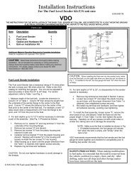
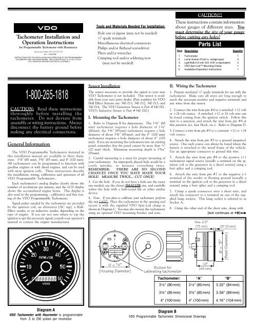
I. Mounting the <strong>Tach</strong>ometer<br />
1. Refer to Diagram B for dimensions. The 3 ¹⁄₈" (80<br />
mm) tachometer requires a hole diameter of 3 ¹⁄₈"<br />
(80mm); the 3 ³⁄₈" (85mm) tachometer requires a hole<br />
diameter of about 3 ³⁄₈" (85mm); <strong>and</strong> the 4" (100 mm)<br />
tachometer requires a hole diameter of about 4 " (100<br />
mm). If you are mounting the tachometer into an existing<br />
panel, remember that the panel cannot be more than ¾"<br />
(20 mm) thick. Minimum mounting depth is 3 ⁹⁄₁₆"<br />
(91mm).<br />
2. Careful measuring is a must for proper mounting of<br />
your tachometer. An improperly placed hole would be a<br />
costly mistake, so measure everything twice.<br />
REMEMBER: THERE ARE NO SECOND<br />
CHANCES ONCE YOU HAVE MADE YOUR<br />
HOLE! MEASURE TWICE... CUT ONCE!<br />
3. Cut the hole. If you do not have a hole saw the exact<br />
size needed, use the closest SMALLER size, <strong>and</strong> carefully<br />
widen the hole <strong>with</strong> a half-round file or other similar<br />
device.<br />
4. Note: If you plan to calibrate your tachometer, perform<br />
this step LAST! Place the tachometer in the opening <strong>and</strong><br />
secure it <strong>with</strong> the supplied <strong>VDO</strong> Spin-Lok clamp as<br />
shown in Diagram C. You may also mount the tachometer<br />
using an optional <strong>VDO</strong> mounting bracket <strong>and</strong> nuts.<br />
II. Wiring the <strong>Tach</strong>ometer<br />
1. Prepare insulated ¼" spade terminals for use <strong>with</strong> the<br />
tachometer. Make sure all wires are long enough to<br />
reach the necessary positive <strong>and</strong> negative terminals <strong>and</strong><br />
any wires from the sensor.<br />
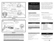
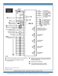
2. Connect the wire from pin #4 to a switched +12 volt<br />
or +24 volt source. A switched +12 or 24 volt wire can<br />
be found coming from the ignition switch. Follow this<br />
wire to a junction, <strong>and</strong> attach the wire from pin #4 at<br />
this junction (i.e. fuse block, etc.). Refer to Diagram D.<br />
3. Connect a wire from pin #5 to a constant +12 or +24<br />
volt source.<br />
4. Attach the wire from pin #3 to a ground (negative)<br />
source. One such source can always be found where the<br />
battery is attached to the metal frame of the vehicle.<br />
Use an appropriate connector to ground this wire.<br />
5. Attach the wire from pin #8 to the positive (+)<br />
tachometer signal source [usually a terminal on the ignition<br />
coil or the generator in a diesel system] using a<br />
butt splice <strong>and</strong> a crimping tool.<br />
6. Attach the wire from pin #7 to the negative (–)<br />
terminal of the sender or floating ground [usually a<br />
terminal on the ignition coil or the generator in a diesel<br />
system] using a butt splice <strong>and</strong> a crimping tool.<br />
7. Crimp a spade connector onto a short wire, <strong>and</strong><br />
attach the connector to a terminal on one of the supplied<br />
lamp sockets. This lamp socket is referred to as<br />
Socket A.<br />
8. Crimp the other end of the short wire, along <strong>with</strong><br />
[text continues at #›]¨<br />
=Qh")<br />
'#]]<br />
!)%]]<br />
<br />
<strong>VDO</strong><br />
<strong>VDO</strong><br />
<br />
<br />
<br />
-²1³<br />
8_ecY^W4YQ]UdUb<br />
<br />
<br />
RPM<br />
2edd_^V_b<br />
SQ\YRbQdY^WdQSX_]UdUb<br />
3¹⁄₈" (80 mm)<br />
3³⁄₈" (85 mm)<br />
!)<br />
$(]]<br />
3¹⁄₈" (80 mm)<br />
3³⁄₈" (85 mm)<br />
2UjU\4YQ]UdUb<br />
<strong>Tach</strong>ometer: “A” “B”<br />
3.32" (84 mm)<br />
3.56" (89 mm)<br />
4" (100 mm)<br />
4" (100 mm)<br />
4.16" (104 mm)<br />
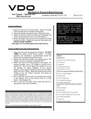
Diagram A<br />
<strong>VDO</strong> <strong>Tach</strong>ometer <strong>with</strong> Hourmeter is programmable<br />
from .5 to 200 pulses per revolution<br />
Diagram B<br />
<strong>VDO</strong> <strong>Programmable</strong> <strong>Tach</strong>ometer Dimensional Drawings
DQSX<br />
CYW^Q\*<br />
2QddUbi<br />
6ecU<br />
2\_S[<br />
4QcX@Q^U\<br />
K!)]]M<br />
=QhY]e]DXYS[^Ucc<br />
˜<br />
F4?C`Y^
œ<br />
3. Analog (Pointer) Calibration ( )<br />
You can adjust the calibration of the tachometer’s analog<br />
display (the pointer showing revolutions per minute) by<br />
using speed test equipment <strong>and</strong> the “ ” function on<br />
the LCD readout. The pointer can be repositioned anywhere<br />
<strong>with</strong>in the calibration range of the tachometer.<br />
To manually calibrate the pointer on the analog display:<br />
1. Press <strong>and</strong> hold in the button on the tachometer as you<br />
turn on the ignition <strong>and</strong> start the engine. Hold in the<br />
button until the word “ ” shows up. When it does,<br />
release the button. Set the RPM using a reference tachometer<br />
at a value above idle (e.g. 2000 RPM).<br />
2. Press the button once, <strong>and</strong> the word “ ” will be<br />
displayed on the LCD readout. Press it twice rapidly<br />
then release it for a second, <strong>and</strong> the word “ ” will be<br />
displayed. So if you need an upward calibration of the<br />
pointer, press the button once. If you need a downward<br />
calibration, press the button twice rapidly <strong>and</strong> release it.<br />
3. When either “ ” or “ ” is showing, press the button<br />
again, <strong>and</strong> hold it in. If you hold the button in for just a<br />
short time, the pointer will move slowly either upwards or<br />
downwards, depending on which mode you selected. This<br />
allows for a very accurate adjustment of the pointer. Holding<br />
the button in for a longer period of time makes the<br />
pointer move faster.<br />
Adjustments between –30% <strong>and</strong> +100% are possible, but<br />
must be done WITH A REFERENCE TACHOMETER<br />
ONLY!!!<br />
It is recommended that these adjustments be done<br />
only by experienced mechanics.<br />
4. When you have repositioned the pointer where you<br />
want it, release the button <strong>and</strong> wait. If no further adjustments<br />
are made <strong>with</strong>in one minute, the tachometer will<br />
revert back to the normal operating mode.<br />
NOTE: If you move the pointer past the upper<br />
limit of the calibration range, the LCD display will<br />
flash <strong>and</strong> you will only be able to adjust the pointer<br />
downward. If you move the pointer past the lower<br />
calibration limit, the LCD display will also flash,<br />
<strong>and</strong> you will only be able to adjust the pointer upward.<br />
4. Fine Calibration<br />
When the ignition is on <strong>and</strong> power is supplied to the<br />
tachometer you can select the fine calibration function<br />
to very accurately adjust the running speed — difference<br />
ratio. This allows for compensation of alternator<br />
slippage over various speed ranges, for example. This<br />
function also allows for syncronization of two engines.<br />
To access <strong>and</strong> use the fine calibration function:<br />
1. Press <strong>and</strong> release the pushbutton on the back of the<br />
tachometer. This enables you to adjust the running<br />
speed/difference ratio between –20% <strong>and</strong> +20%.<br />
Adjustments are made in (+) or (–) steps of 0.5% by<br />
pressing <strong>and</strong> holding the button. When the adjustment<br />
is complete, release the button. After a short time, the<br />
display reverts back to its normal mode. See Diagram J<br />
for examples of:<br />
Display 1: 0.0% difference to the adjusted value;<br />
Display 2: 2.0% difference to the adjusted value;<br />
Display 3: 2.5% difference to the adjusted value.<br />
TO COMPLETE THE INSTALLATION:<br />
Perform Step 4 of Section One on Page 1. When the<br />
tachometer is secure in the panel, your installation is<br />
finished.<br />
Operating voltage:<br />
Operating current:<br />
Operating temperature:<br />
Protection:<br />
Dimensions—<br />
Depth:<br />
Diameter:<br />
Illumination:<br />
TECHNICAL DATA<br />
Calibration range:<br />
10.8 – 32 Volts<br />
< 100 mA<br />
(< 600 mA <strong>with</strong> light)<br />
– 4° F to 158° F<br />
(-20° C to 70° C)<br />
IP65 (Front)<br />
Ozone <strong>and</strong> UV<br />
resistant housing<br />
3.6" (91 mm)<br />
3 ¹⁄₈" (80 mm)<br />
3 ³⁄₈" (85 mm)<br />
4" (100 mm)<br />
Backlit / Frontlit<br />
dial <strong>and</strong> display<br />
0.5 to 200 pulses<br />
per revolution<br />
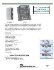
Programming<strong>Tach</strong>ometers <strong>with</strong> Generator Sender<br />
1. Use pulse instruction to program tachometer.<br />
2. Must use tachometer <strong>with</strong> engine hour meter.<br />
3. If your ratio is 1:1 use 4 pules<br />
If your ratio is 2:1 use 2 pules<br />
GXU^i_ecUU²1TZecd³<br />
@ecX_^SUQ^T²E`³<br />
YcTYc`\QiUT<br />
<strong>VDO</strong><br />
BQ`YT\i`ecXdgYSU<br />
d_cUU²4>³KV_b<br />
T_g^M<br />
<strong>VDO</strong><br />
Adjust pointer by pushing<br />
<strong>and</strong> holding in the<br />
button on the<br />
rear of the tachometer<br />
then<br />
or<br />
Example #1<br />
Example #2<br />
Example #3<br />
Diagram I<br />
Calibration of the analog (pointer) display on the<br />
tachometer<br />
Diagram J<br />
Fine calibration of the tachometer reading