SVF Ball Valves - Flow Components, Inc.
SVF Ball Valves - Flow Components, Inc.
SVF Ball Valves - Flow Components, Inc.

You also want an ePaper? Increase the reach of your titles
YUMPU automatically turns print PDFs into web optimized ePapers that Google loves.
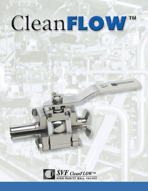
<strong>SVF</strong> CleanFLOW<br />
HIGH PURITY BALL VALVES
The latest ASME/BPE guideline for valve and tubing<br />
designs used in biotech and pharmaceutical applications<br />
provides process engineers with a reliable<br />
and measurable valve selection criteria.<br />
After years of successful installations throughout the<br />
pharmaceutical industry, <strong>SVF</strong> <strong>Flow</strong> Controls, <strong>Inc</strong>.now<br />
offers a fully compliant high purity ball valve that meets<br />
these stringent guidelines.<br />
CleanFLOW ball valves are engineered to be a true<br />
process piping component to specifically meet the<br />
demanding processes found in the pharmaceutical, biotech,<br />
semiconductor, cosmetics, foods and other industries<br />
where particle generation and contamination can<br />
threaten the outcome of the product. The port opening of<br />
the valve’s flow path is dimensionally identical to the adjacent<br />
tubing. This “Tube-ID” feature provides predictable<br />
flow rates and pressure drops and ensures thorough<br />
cleaning and full drainability as mandated by ASME/BPE.<br />
As a BPE-compliant product, CleanFLOW valves may<br />
be specified and installed plant-wide making the process<br />
of design, construction, startup and maintenance easier<br />
to manage while helping to minimize overall project costs.<br />
“We are pleased to recommend CleanFLOW valves to<br />
help you meet the critical demands of a BPE-compliant,<br />
high purity piping system.”<br />
CleanFLOW High Purity ball<br />
valves add a new level of quality and<br />
performance to High Purity and aseptic<br />
processes.<br />
CleanFLOW valves are engineered<br />
and designed to specifically<br />
meet the demanding process found in<br />
the Pharmaceutical Biotech,<br />
Semiconductor, Cosmetic, Food and<br />
other industries where microbial, particle<br />
generation and contamination can<br />
threaten the outcome of the product.<br />
Our design team through years of<br />
experience, has developed a valve<br />
that is unparalleled for high purity,<br />
high vacuum, high cycle and may be<br />
used in a wide range of pressure and<br />
temperature applications.<br />
Only the finest and highest quality materials,<br />
available from certified suppliers and manufacturers<br />
go into the producing the CleanFLOW ball<br />
valve. All materials used are inspected with the<br />
most stringent and advanced techniques possible<br />
to insure quality control and superipr performance.<br />
2
CleanFLOW<br />
TM<br />
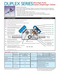
Clean<strong>Flow</strong> High-Purity <strong>Ball</strong> <strong>Valves</strong><br />
Bottom entry 316L precision<br />
machined stem with live loaded high<br />
cycle stem packing, automatically<br />
adjusts with pressure and temperature<br />
fluctuations.<br />
Solid 316L stainless steel ball with<br />
“Tube-ID” feature maintains full flow<br />
rate, reduces pressure drops and is<br />
fully drainable.<br />
ISO 5211 Integral Mounting Pad<br />
Allows for precise actuator mounting<br />
or secondary containment unit.<br />
Vinyl covered stainless steel handle<br />
indicates direction of flow.<br />
Available in a variety of colors.<br />
Encapsulated heavy duty stainless<br />
steel body bolts are protected from<br />
outside environment and are ideal<br />
for washdowns.<br />
PTFE-TFM® seats feature nonslotted<br />
hygienic design eliminating<br />
entrapment areas, smoother surface<br />
reduces torque and particle<br />
generation, FDA compliant and<br />
ideal for clean steam applications.<br />
(PTFE-TFM ® cavity filler available)<br />
Interior standard finish of 20 Ra<br />
insures cleanliness and low<br />
friction.Electro-polishing and<br />
finishes as low as 5 Ra available.<br />
Integral Bosses allows for purge<br />
ports be added for CIP or SIP<br />
applications.<br />
316L Stainless Steel Center Section<br />
allows easy access to internal valve<br />
components without disturbing alignment<br />
of tubing. Functions as both<br />
valve and union.<br />
Variety of end connections available<br />
including clamp end, buttweld,<br />
extended buttweld(ETO), socket weld,<br />
flush bottom tank pad, compression<br />
end.<br />
Fully encapsulated body seals<br />
allows in line welding without<br />
disassembly, maintains sealing<br />
integrity from high vacuum to high<br />
pressure and temperature applications.<br />
3
Typical CleanFLOW Applications<br />
Pharmaceutical/Biotechnology<br />
• High Purity Water<br />
• Clean Steam<br />
• WFI (water for injection)<br />
• Gas and Air Delivery<br />
• Cleaning Solutions<br />
• Alcohol<br />
Semiconductor/Microelectronics<br />
• Vacuum<br />
• High Purity Gases<br />
• Toxic Gases<br />
• Solvents (IPA, ketones)<br />
• Tool Hookup<br />
Cosmetics<br />
• Creams<br />
• Oils<br />
• Alcohol<br />
• Waxes<br />
• Detergents<br />
Our exclusive quad-piston pneumatic actuator is ideally<br />
suited for high density piping systems. The Compact4 is<br />
powerful and lightweight and is available with a full<br />
range of modular control accessories.<br />
4
Performance Data<br />
Seats<br />
Clean<strong>Flow</strong> ball valves feature high-performance TFM seat materials;s as standard.<br />
TFM is chemically modified PTFE that fills the gap between conventional PTFE and melt-processable PFA.<br />
Compared to conventional PTFE, TFM, has the following enhanced properties: Much lower deformation<br />
under pressure (cold flow) at room and elevated temperatures. Lower permeability. May be used at higher<br />
pressures. Our seat specification reads as follows:<br />
Seats - Pure TFM, (FDA, USP23 Class VI), Non-slotted, designed to meet ASME/BPE SD 3.6.1, SG-4.1.1.8,<br />
SG4.1.1.6.<br />
Body Seals<br />
Clean<strong>Flow</strong> encapsulated PTFE seal design eliminates possible entrapment area between valve body and<br />
ends, also facilitates inline welding without disassembly. Optional body seal material is available when<br />
required.<br />
C V Factors For CleanFLOW <strong>Ball</strong> <strong>Valves</strong><br />
Size Port C V<br />
1/2 .37 8<br />
3/4 .62 29<br />
1 .87 66<br />
1-1/2 1.37 192<br />
C V is defined as the number of U.S. gallons per minute<br />
that water will flow thorough a valve at 1 p.s.i drop.<br />
**Pressure Rating<br />
C.W.P (cold working pressure)<br />
1/2 thru 2” 1500 PSI<br />
2-1/2 thru 4” 720 PSI<br />
W.S.P (working steam pressure)<br />
1/2” thru 4” 150 P.S.I-366˚F<br />
CleanFLOW valves may be used at higher<br />
pressures and temperatures using either<br />
NRG or PEEK seats. Please consult factory<br />
for exact specifications.<br />
Vacuum Rating.<br />
CleanFLOW valves provide excellent<br />
performance under vacuum conditions and<br />
have been helium leak tested to 1 x 10⁻⁹.<br />
Data upon request.<br />
TORQUE DATA (IN.LB.)<br />
PTFE-TFM ® SEATS<br />
1/2” 25 2” 200<br />
3/4” 35 2 1/2” 300<br />
1” 60 3” 400<br />
1 1/2” 150 4” 700<br />
Torque values shown represent ideal conditons.<br />
For exact figures consult factory<br />
Size Port C V<br />
2 1.87 434<br />
2-1/2 2.37 723<br />
3 2.87 1124<br />
4 3.83 2100<br />
** Note: Clean<strong>Flow</strong> valves with TR ends are rated to Tri<br />
Clover specifications<br />
* Cavity filler are not recommended for steam service.<br />
Available Options & Accessories<br />
Cavity Filler*- seats of PTFE-TFM ® eliminate the<br />
dead space between the ball and valve body.<br />
Purge Ports- for C.I.P or S.I.P applications.<br />
Polishing- Mechanical or electropolishing to<br />
5Ra.<br />
Actuation- Pneumatic or electric automation<br />
packages for ON/OFF or proportional control.<br />
Flush Mounted Tank Pads- eliminate the dead<br />
leg between tank and valve.<br />
Handles- variety of options including Locking,<br />
Oval, Extended, Spring return, Fusible link or<br />
Color coded.<br />
Ends- variety of options including, Cherry Burrell<br />
I and Q-line, KF, socket weld tube, compression,<br />
150lb and 300lb flanges.<br />
Materials- Hastelloy, Alloy 20, Monel, AL6XN or<br />
Titanium.<br />
Secondary Containment Unit-Designed to<br />
retrofit existing valve. Prevents possible leaks to<br />
outside environment.<br />
Cryogenic-For applications to - 410˚F.<br />
Pro-Spec- <strong>SVF</strong>s innovative design team can<br />
customize valves for unique applications.<br />
PTFE-TFM ® is a trademark of Dyneon<br />
5
Surface Measurement<br />
Measuring and specifying surface finish has, until recently, been left to a varying amount of<br />
speculation. The number of different standards being used by different equipment manufacturer<br />
has created a great deal of confusion and misunderstanding throughout the industry. With the<br />
advent of ASME/BPE the pharmaceutical and biotechnology industries finally have a standard<br />
that it can be universally applied.<br />
*Table SF-5 Acceptance criteria for interior surface finishes of valve bodies<br />
Anomaly or Indication<br />
Acceptance Criteria<br />
Cluster of pits<br />
Demarcation<br />
Grit lines<br />
Nicks (per tube length)<br />
Oxides<br />
Pits<br />
Porosity<br />
Scratches<br />
Surface cracks<br />
Surface inclusion<br />
Surface residuals<br />
Surface roughness (Ra)<br />
Water stains<br />
Weld dross<br />
None accepted.<br />
If 5% of the total area when visually inspected and Ra is met<br />
If Ra is met.<br />
f depth < 0.010 in.<br />
Not accepted.<br />
If dia < 0.020 in. and bottom is shiny.<br />
If dia < 0.010 in. and bottom is shiny.<br />
f length < 0.25 in., depth < 0.003 in., and Ra is met.<br />
None accepted.<br />
If Ra is met and there is no liquid penetrant indication.<br />
None accepted.<br />
See Table SF-6.<br />
If not deposits.<br />
None accepted.<br />
Table SF-6 Ra Readings for <strong>Valves</strong><br />
Mechanically Polished<br />
Ra Average<br />
[Note (1)]<br />
Ra Max<br />
Surface<br />
Designation µ-in. µm µ-in. µm<br />
SFV1 15 0.375 20 0.5<br />
SFV2 20 0.5 25 0.625<br />
SFV3 25 0.625 30 0.75<br />
Standard<br />
Grit<br />
Conversion Chart<br />
R a<br />
µ-in. µm<br />
µ-in.<br />
RMS<br />
µm<br />
150g<br />
27-32<br />
.68-.80<br />
30-35<br />
.76-.89<br />
Mechanically Polished and<br />
Electropolished<br />
180g<br />
240g<br />
18-23<br />
14-18<br />
.46-.58<br />
.34-.46<br />
20-25<br />
15-20<br />
.51-.64<br />
.38-.51<br />
Ra Average<br />
[Note (1)]<br />
Ra Max<br />
Surface<br />
Designation µ-in. µm µ-in. µm<br />
SFV4 10 0.25 15 0.375<br />
SFV5 15 0.375 20 0.5<br />
SFV6 20 0.5 25 0.625<br />
320g<br />
8-10<br />
.21-.25<br />
9-11<br />
.23-.28<br />
General Note: All Ra readings are taken across the grain.<br />
Note:<br />
(1) The average Ra is derived from two readings taken at different locations.<br />
Other Ra readings are available if agreed upon between vendor and<br />
owner/user.<br />
*Table SF-5 from ASME/BPE-1997<br />
Grit: Measures the number of scratches per linear inch of abrasive pad. Higher numbers<br />
indicate a smoother finish.<br />
RMS: Defined as Root Mean Square roughness, this method measures a sample for<br />
peaks and valleys. Lower numbers indicate a smoother finish.<br />
Ra: Known as the Arithmetic Mean, this measurement represents the average value of<br />
all peaks and valleys. Lower numbers indicate a smooth finish.<br />
6
Surface Finish<br />
The importance of surface finish in the pharmaceutical and biotechnology industries is due to<br />
concerns of possible microbial contamination. A smooth finish that is free of cracks, crevasses<br />
and inclusions is inherently easier to clean and maintain in an aseptic condition. The method of<br />
achieving a smooth surface varies from pharmaceutical equipment manufacture to manufacture<br />
using mechanical, chemical and electro polishing techniques.<br />
Mechanical Polishing Procedures<br />
CleanFLOW valves use a mechanical polishing technique that utilizes multiple passes with<br />
progressively finer grits to produce the required standard finish. The parts are either hand held<br />
during the process or fixtured for spinning on polishing lathes or die grinders. Aluminum Oxide<br />
and Silicone Carbide are used for the coated abrasive grit. Buffing compounds are not used in<br />
our polishing process. After inspection to insure proper finish requirements are achieved, valve<br />
parts are ready to be either cleaned or electro polished before final assembly.<br />
Electrol Polishing<br />
Electro polishing is the opposite of the plating process it utilizes a combination of electric current<br />
and chemicals to remove surface material rather then add to it. It is the most effective method of<br />
removing burr, folds, inclusions and other abnormalities. Peaks are removed quicker than valleys<br />
because of the concentration of current on the peaks. This process leaves the surface extremely<br />
smooth and is far easier to clean by reducing the total area required to be sterilized. This electrolytic<br />
process is frequently specified because of the broad range of inherent benefits over<br />
mechanical polishing alone.<br />
Electro Polishing Benefits<br />
* Enhances Cleanability.<br />
* Passivates surface for greater corrosion resistance.<br />
* Removes inclusions and entrapped contaminants such as lubricants and grit particles.<br />
* Leaves surface with highly reflective luster finish.<br />
* Eliminates smeared or torn surface caused by machining or abrasives.<br />
Diagrams showing<br />
progressive<br />
removal of<br />
metal by electropolishing<br />
to<br />
provide an even<br />
surface profile.<br />
7
Valve <strong>Components</strong><br />
1/2” - 2 1/2” 3” - 4”<br />
Part No.<br />
Part<br />
Qty<br />
Description<br />
Part No.<br />
Part<br />
Qty<br />
Description<br />
1<br />
Body<br />
1<br />
316L, ASTM A351-CF3M<br />
13<br />
Packing Nut<br />
1<br />
Stainless Steel 316<br />
2<br />
Pipe Ends<br />
2<br />
316L, ASTM A351-CF3M<br />
14<br />
Lock Tab<br />
2<br />
Stainless Steel 309<br />
3<br />
<strong>Ball</strong><br />
1<br />
316L<br />
15<br />
Handle ( 1 /4”-2”)<br />
1<br />
Stainless Steel 304<br />
4<br />
Stem<br />
1<br />
316L<br />
15A<br />
Wrench (3” & 4”)<br />
1<br />
Stainless Steel 304<br />
5<br />
Valve Seat<br />
2<br />
PTFE-TFM, NRG, PEEK, Cavity Filler PTFE-TFM<br />
15B<br />
Wrench Block<br />
2<br />
Stainless Steel 304<br />
6<br />
Valve Seal<br />
2<br />
PTFE<br />
15C<br />
Hex Head Bolt<br />
2<br />
Stainless Steel 304<br />
7<br />
Thrust Bearing<br />
1<br />
PTFE<br />
16<br />
Lock Washer<br />
1<br />
Stainless Steel 304<br />
7A<br />
Stem Location<br />
Ring (3”& 4”)<br />
1<br />
Stainless Steel 316<br />
17<br />
18<br />
Handle Nut ( 1 /4”-2”)<br />
Body Bolts<br />
1<br />
1<br />
Stainless Steel 316<br />
Stainless Steel 316<br />
8<br />
Thrust Bearing<br />
1<br />
Peek<br />
18A<br />
Body Bolt<br />
1<br />
Stainless Steel 304<br />
8A<br />
Thrust Bearing<br />
1<br />
Peek<br />
19<br />
Nuts<br />
2<br />
Stainless Steel 304<br />
9<br />
9A<br />
Stem Packing<br />
Stem Packing<br />
(3”& 4”)<br />
2<br />
3<br />
RT-TFE<br />
PTFE<br />
20<br />
21<br />
Stop Pin<br />
Stop Plate<br />
3<br />
1<br />
Stainless Steel 304<br />
Stainless Steel 304<br />
10<br />
Seal Protector<br />
1<br />
Peek<br />
22<br />
Seat Retainer<br />
1<br />
Stainless Steel CF3M<br />
11<br />
Gland Packing<br />
1<br />
Stainless Steel 316L<br />
12<br />
Belleville Washer<br />
2<br />
Stainless Steel<br />
8
Dimensions & Weight 1 ⁄2 ” - 2 1 ⁄2 ”<br />
size<br />
A A1 D E F G H M N P I.D. &<br />
PORT<br />
TR ETO<br />
Tube<br />
O.D.<br />
ISO<br />
WEIGH<br />
(lbs)<br />
1/2”<br />
3.50<br />
5.50<br />
1.75<br />
1.50<br />
1/4 - 20<br />
0.22<br />
1.76<br />
1.00<br />
4.50<br />
M5<br />
0.37<br />
0.50<br />
F03<br />
1.50<br />
3/4”<br />
4.00<br />
6.00<br />
2.05<br />
1.59<br />
1/4 - 20<br />
0.22<br />
1.87<br />
1.00<br />
4.50<br />
M5<br />
0.62<br />
0.75<br />
F03<br />
1.75<br />
1”<br />
4.50<br />
6.50<br />
2.42<br />
2.19<br />
5/16 -18<br />
0.30<br />
2.40<br />
1.17<br />
5.75<br />
M5<br />
0.87<br />
1.00<br />
F04<br />
3.20<br />
1”-1/2”<br />
5.50<br />
7.50<br />
3.16<br />
2.88<br />
3/8 -16<br />
0.35<br />
3.16<br />
1.39<br />
7.00<br />
M6<br />
1.37<br />
1.50<br />
F05<br />
8.00<br />
2”<br />
6.25<br />
8.00<br />
3.56<br />
3.06<br />
3/8 -16<br />
0.35<br />
3.35<br />
1.39<br />
7.00<br />
M6<br />
1.87<br />
2.00<br />
F05<br />
13.00<br />
2”-1/2”<br />
6.75<br />
9.50<br />
4.90<br />
4.80<br />
M20<br />
0.55<br />
5.83<br />
2.80<br />
10.00<br />
M8<br />
2.37<br />
2.50<br />
F07<br />
23.00<br />
Dimensions & WEIGHT 3” - 4”<br />
size<br />
A A1 D F G H J L K T I.D. &<br />
PORT<br />
TR ETO<br />
ISO<br />
Tube<br />
O.D.<br />
WEIGH<br />
(lbs)<br />
3”<br />
7.00<br />
10.50<br />
6.70<br />
1”-14 UNS<br />
.745<br />
7.25<br />
1.75<br />
3.37<br />
13.8<br />
M10<br />
2.87<br />
F10<br />
3.00<br />
32<br />
4”<br />
8.50<br />
12.50<br />
8.00<br />
1”-14 UNS<br />
.745<br />
8.00<br />
1.75<br />
3.37<br />
22.0<br />
M10<br />
3.83<br />
F10<br />
4.00<br />
47<br />
For 1/4”, 3/8” and 6” contact factory<br />
9
TSB7 Series Three Way Valve<br />
The CleanFLOW TSB7 Series three-way valve is an ideal choice for high purity piping<br />
systems. Its inherent design features can replace two or three standard valves, saving<br />
space and reducing costs.<br />
At the heart of the TSB7 design is the use of a common port that facilitates tri-directional<br />
flow requirements, eliminating deadlegs and in its optimal position is fully drainable. The<br />
common port can either be located at the bottom or side of the valve. The existing seats<br />
on the two remaining ports provide positive shutoff.<br />
Three-way <strong>Ball</strong> Configurations<br />
Side<br />
Entry<br />
Bottom,<br />
Entry<br />
Side Entry<br />
L-Port,<br />
90 0 Turn<br />
Side Entry<br />
T-Port,<br />
90 0 Turn<br />
Side Entry<br />
T-Port,<br />
90 0 Turn<br />
Side Entry<br />
T-Port,<br />
180 0 Turn<br />
Bottom Entry<br />
L-Port,<br />
360 0 Turn<br />
Bottom Entry<br />
L-Port,<br />
180 0 Turn<br />
Bottom Entry<br />
LL-Port,<br />
90 0 Turn<br />
Bottom Entry<br />
T-Port,<br />
90 0 Turn<br />
Bottom Entry<br />
TT-Port,<br />
180 0 Turn<br />
SL1 ST1 ST2<br />
BL3<br />
BT1<br />
ST3<br />
BL2<br />
BT2<br />
BL1<br />
1 6 6 A T TR ST1 OPTIONS<br />
TSB7<br />
SIZE<br />
STYLE<br />
BODY &<br />
END MATERIAL<br />
BALL & STEM<br />
MATERIAL<br />
SEAT SEAL ENDS<br />
FLOW<br />
PATTENY<br />
OPTIONS<br />
1/2”<br />
3/4”<br />
1”<br />
1-1/2”<br />
2”<br />
2-1/2”<br />
3”<br />
4”<br />
TSB7<br />
(Non-<br />
Cavity<br />
Filled)<br />
TSBC7<br />
(Cavity<br />
Filled)<br />
6 - CF3M<br />
(316L)<br />
6 - 316L A - TFE - TFM<br />
N - NRG<br />
K - PEEK<br />
A - TFE<br />
E - EPDM<br />
V - VITON<br />
TR - T - Clamp<br />
ETO - Extended<br />
Tube OD<br />
Cherry Burrell<br />
I - I Line<br />
S - S Line<br />
Q -Q Line<br />
ST1<br />
ST2<br />
SL1<br />
BT1<br />
BT2<br />
BL1<br />
BL2<br />
BL3<br />
• Purge Ports<br />
• Oval Handle<br />
• Spring Return<br />
Handle<br />
• Locking<br />
Device<br />
• Electro-Polish<br />
• Fusible Link<br />
• Stem<br />
Extentions<br />
10
Dimensions & Weight 1 ⁄2 ” - 2 1 ⁄2 ”<br />
3” & 4” consult factory for dimensions<br />
11
<strong>SVF</strong> CleanFLOW<br />
HIGH PURITY BALL VALVES<br />
Use this information to create your ASME/BPE compliant high purity ball valve specification.<br />
High purity ball valve shall be a three piece design with ISO 5211 integral actuator mounting<br />
pad, removable swing-out center section, non-exposed body bolting and encapsulated body<br />
seals. The ID for the valve flow path (ball, seats, ends) shall be the same ID as the tubing it<br />
is attached to as per ASME/BPE 1997 SD.3.7.9.<br />
A. Body materials - 316L Stainless Steel ASTM A351 CF3M.<br />
B. <strong>Ball</strong> Materials - 316L Stainless Steel ASTM A479 or ASTM A351CF3M.<br />
C. End Connections.<br />
I. Clamp style -316L Stainless Steel A351 CF3M (dimension per ASTM/BPE 1997 DT-10<br />
II. Extended Buttweld (ETO) - 316L ASTM A-270 chemical composition and dimensions per<br />
ASTM/BPE 1997 table and DT-3 and DT-5<br />
D. Stem -316L Stainless Steel ASTM A479, live-loaded, blowout proof design.<br />
Stem packing seals to be a combination of PEEK (Poly Ether Ether ketone) and TFE<br />
conforming to ASTM/BPE 1997 SG-4.1.1.1.<br />
E. Seats - PTFE-TFM, (FDA, USP 23 Class VI), non-slotted, designed to meet ASTM/BPE,<br />
1997 SD 3.6.1, SG-4.1.1.8, SG-4.1.1.8, SG-4.1.1.6 and rated for steam pressure of 150<br />
psi at 366 F°<br />
F. Interior Finish - Polished to meet ASTM/BPE 1997 specification DT-12 and Table SF-6.<br />
I. Mechanical Polish to SFV 1<br />
II. Electro-Polish to SFV 4<br />
G. Markings - <strong>Valves</strong> shall be marked to comform with ASTM-BPE 1997 DT-3.<br />
H. Packaging - <strong>Valves</strong> to be packaged to conform with ASTM/BPE 1997 DT-13.<br />
Contact <strong>SVF</strong> for a copy of our “Engineering Manual on High Purity <strong>Ball</strong> <strong>Valves</strong>”.<br />
1 6 6 6 6 A T TR OPTIONS<br />
SB7<br />
SIZE<br />
STYLE<br />
BODY &<br />
END MATERIAL<br />
BALL & STEM<br />
MATERIAL<br />
SEAT SEAL ENDS OPTIONS<br />
1/2”<br />
3/4”<br />
1”<br />
1-1/2”<br />
2”<br />
2-1/2”<br />
3”<br />
4”<br />
SB7<br />
(Non-<br />
Cavity<br />
Filled)<br />
SBC7<br />
(Cavity<br />
Filled)<br />
6 - CF3M<br />
(316L)<br />
6 - 316L A - TFE - TFM ®<br />
N - NRG<br />
P - PEEK<br />
T - TFE TR - T- Clamp ®<br />
ETO - Extended<br />
Tube OD<br />
Cherry Burrell<br />
I - I Line<br />
S - S Line<br />
Q - Q Line<br />
T - Bottom<br />
• Purge Ports<br />
• Oval Handle<br />
• Spring Return<br />
Handle<br />
• Locking<br />
Device<br />
• Electro-Polish<br />
• Fusible Link<br />
• Stem extention<br />
Due to continuous development of our product range, we reserve the right to alter the dimensions and information contained in this leaflet as required.<br />
TFM ® is a trade mark of DYNEON<br />
13560 Larwin Circle, Santa Fe Spring, CA 90670 Phone 800-783-7836 Fax 562-802-3114<br />
•E-MAIL sevice@svf.net • sales@svf.net • WEB SITE www.svfflowcontrols.com