Air supply valve STH - Stork Air
Air supply valve STH - Stork Air
Air supply valve STH - Stork Air

Create successful ePaper yourself
Turn your PDF publications into a flip-book with our unique Google optimized e-Paper software.
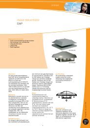
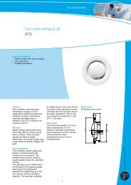
<strong>Air</strong> <strong>supply</strong> <strong>valve</strong><br />
<strong>STH</strong><br />
Important features<br />
• Made of high-quality plastic<br />
• High inductive capacity<br />
• Variable adjustment<br />
• Pre-adjustable by adjustment indication<br />
• Low noise level<br />
• Secured setting<br />
General<br />
Due to its highly inductive capacity,<br />
this ventilation <strong>valve</strong> may be<br />
applied for air with a temperature<br />
both above and below room<br />
temperature. The maximum air<br />
volume is 50 m³/h. The inductive<br />
capacity depends on the exit<br />
velocity of the ventilation <strong>valve</strong>.<br />
Material<br />
The <strong>valve</strong> is made of white (RAL<br />
9010) high-quality plastic and is<br />
fitted with a rubber fastening ring<br />
which also ensures a perfect seal.<br />
Capacity/setting<br />
The ventilation <strong>valve</strong>s' graphs are<br />
based on measurements with<br />
straight duct connections. The<br />
pressure drop over the <strong>valve</strong>s is<br />
usually slightly higher for underfloor<br />
ducting. Valve setting S (see<br />
dimensioned sketch) is determined<br />
on the basis of the graph, which<br />
gives the relationship between the<br />
overpressure in the duct system<br />
and the quantity of air supplied.<br />
This setting is made by means of<br />
the adjustment screw. After<br />
inspection and approval of the<br />
18<br />
Accessoires<br />
<strong>supply</strong> air, the adjustment screw is<br />
covered by the supplied cap. The<br />
marks on the guide plate of the<br />
<strong>valve</strong> cone serve to indicate<br />
ventilation position S . The first<br />
mark corresponds with the smallest<br />
S setting = 5 mm. The following<br />
marks each represent steps of 2<br />
mm. S = 7, 9, 11, 13 and 15 mm.<br />
This marking allows for presetting<br />
of the <strong>valve</strong>s. To prevent dust<br />
deposit due to induction, the <strong>valve</strong><br />
setting is limited to a minimum of 5<br />
mm as standard. In case a smaller<br />
<strong>valve</strong> setting is required, this can<br />
be reduced by breaking away one<br />
of the projections.<br />
Noise<br />
The <strong>supply</strong> diffuser produces very<br />
little noise: for 50 m³/h, for<br />
instance, less than 22 dB(A) at 10<br />
m² Sabine.<br />
Option<br />
• Clean sector, type-indication<br />
<strong>STH</strong> 125a<br />
In practice, it may be impossible<br />
to install the <strong>STH</strong> <strong>valve</strong> at 35 cm<br />
or more from the wall or the<br />
ceiling. In this situation, the so-<br />
called clean sector offers a<br />
solution. Installation of this clean<br />
sector in the <strong>valve</strong> will prevent<br />
the air from being blown along<br />
the nearest wall (see illustration).<br />
The position of the clean sector<br />
is indicated on the outer side of<br />
the <strong>STH</strong> <strong>valve</strong> by means of an<br />
arrow.
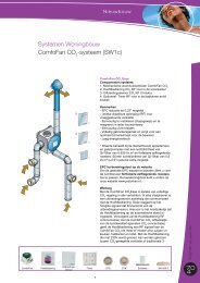
Capacity graphs<br />
See image 5.1.<br />
Accessoires<br />
<strong>Air</strong> <strong>supply</strong> <strong>valve</strong><br />
<strong>STH</strong><br />
Positioning (inflow below room<br />
temperature)<br />
The most favourable position of the<br />
<strong>supply</strong> diffuser is at least 35 cm<br />
(vertically) under the ceiling and at<br />
least 35 cm (horizontally) from the<br />
corner of two walls (see<br />
illustration). Optimum use of the<br />
Coanda-effect.<br />
See image 5.2.<br />
19
<strong>Air</strong> <strong>supply</strong> <strong>valve</strong><br />
<strong>STH</strong><br />
Image 5.1<br />
Image 5.2<br />
20<br />
Accessoires
Accessoires<br />
21