TX6400 User Manual - Trolex
TX6400 User Manual - Trolex
TX6400 User Manual - Trolex

You also want an ePaper? Increase the reach of your titles
YUMPU automatically turns print PDFs into web optimized ePapers that Google loves.
<strong>TX6400</strong> <strong>User</strong> <strong>Manual</strong><br />
<strong>TX6400</strong> Sentrum<br />
Contents<br />
1. Principle of Operation 4<br />
2. Application 5<br />
2.1 System Overview 5<br />
2.1.1 Gas Detection 6<br />
2.1.2 Flow Monitoring 7<br />
2.1.3 Control and Data Collection 7<br />
2.1.4 Sentrum System Block Diagram 8<br />
3. Technical Details 9<br />
3.1 <strong>TX6400</strong> Sentrum Methane<br />
Recovery Monitoring System 9<br />
3.1.1 Monitors 9<br />
3.1.2 Specification 9<br />
3.2 TX6363 Infrared Methane<br />
Sensor 11<br />
3.2.1 Features 11<br />
3.2.2 Specification 11<br />
3.3 TX6363 Infrared Carbon Dioxide<br />
Sensor 12<br />
3.3.1 Features 12<br />
3.3.2 Specification 12<br />
3.4 TX6373 Oxygen Sensor 12<br />
3.4.1 Features 12<br />
3.4.2 Specification 12<br />
3.5 P5557.13 Mass Flow System 13<br />
3.5.1 Features 13<br />
3.5.2 Specification 13<br />
3.6 P5557.10 Dual Pump Controller 13<br />
3.6.1 Features 13<br />
4. Installation 14<br />
4.1 Main Enclosure 14<br />
4.2 Transport Pipe Preparation 15<br />
4.3 Gas Monitoring System 16<br />
4.4 Flow Monitoring System 17<br />
4.5 Power Supply 17<br />
5. Commissioning 18<br />
5.1 The TX9042 Programmable<br />
Sensor Controller 20<br />
5.1.1 TX9042 Signal Display 20<br />
5.2 TX9042 Main Methane<br />
Drainage Monitor Setup 21<br />
5.3 Resetting the Accumulated<br />
Mass Totals 22<br />
5.4 Taking a Gas Sample for<br />
Analysis 22<br />
5.5 Updating the Analysis Values 23<br />
5.6 Mass Flow Setup 23<br />
5.7 Flow Monitoring 25<br />
5.8 Gas Monitoring 25<br />
6. Operation and Maintenance 26<br />
6.1 Monitoring Accuracy 26<br />
6.2 Water Filter 26<br />
6.3 Pump Maintenance 27<br />
7. Modbus Address Registers 28<br />
8. TX9042 Display Formats 31<br />
Disclaimers 33<br />
Trademarks 33<br />
Contact Details 33<br />
Document History 33<br />
www.trolex.com<br />
<strong>TX6400</strong>-UM-EN-01 3
1. Principle of Operation<br />
<strong>TX6400</strong><br />
RS485 Modbus output signal to transmit live data and interface with<br />
surface control room SCADA system.<br />
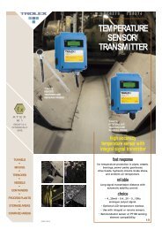
The <strong>Trolex</strong> <strong>TX6400</strong> Sentrum Monitoring System is designed to provide the complete<br />
solution for Methane Recovery Monitoring applications. Using proven technology,<br />
the <strong>TX6400</strong> was developed to measure methane at source and at strategic points<br />
throughout the methane pipe network.<br />
4 <strong>TX6400</strong>-UM-EN-01<br />
www.trolex.com
<strong>TX6400</strong> <strong>User</strong> <strong>Manual</strong><br />
Complex algorithms are used to correct for the effects of non-methane hydrocarbon<br />
cross sensitivity, together with mass flow calculations, providing all the required<br />
information in one package to monitor the efficiency of the methane recovery<br />
system allowing purity problems to be resolved quickly, thus improving safety and<br />
methane capture.<br />
Simple plug-in connections for monitoring allow for easy installation and<br />
maintenance. Using RS485 Modbus communication protocol, live data can be<br />
transmitted to the surface control room SCADA for continuous real time monitoring<br />
and data logging.<br />
2. Application<br />
• Coal Mine Methane Extraction<br />
• Coal Bed Methane Extraction<br />
• Abandoned Mine Methane Extraction<br />
• Gas to Energy Projects<br />
• Clean Development Mechanism (CDM) Projects<br />
• Methane Purity Monitoring<br />
• Underground monitoring at coal face boreholes<br />
• Underground monitoring at strategic points along the methane pipe network<br />
• Monitoring the methane purity and gas flow either before or after the surface<br />
methane extraction pump<br />
Group 1:<br />
<strong>TX6400</strong><br />
Supply Voltage:<br />
12 V dc<br />
2.1 System Overview<br />
The system will monitor the quality and quantity of methane being extracted. A<br />
Gas Chromatograph Analysis of the gas to be monitored will be required before<br />
commissioning. The results from the Gas Chromatograph Analysis are entered in<br />
the TX9042 Programmable Sensor Controller. These values can be adjusted as gas<br />
concentrations change over time. Regular Gas Chromatograph Analysis will be<br />
required to verify system accuracy and enable gas composition adjustment. Sensor<br />
recalibration will be required on a six monthly basis. Refer to the individual sensor<br />
<strong>User</strong> <strong>Manual</strong>s and Product Data Sheets for specific information on the sensors.<br />
www.trolex.com<br />
<strong>TX6400</strong>-UM-EN-01 5
2.1.1 Gas Detection<br />
Gas travelling along a transport pipe prior to being used, destroyed or stored will<br />
be sampled using infrared gas sensing equipment. Using mathematical algorithms,<br />
the methane purity will be calculated and displayed on the TX9042 Programmable<br />
Sensor Controller. The values displayed will be corrected for the effects of nonmethane<br />
hydrocarbons (ethane, propane and butane).<br />
The gas will pass through a drying process to remove moisture prior to being<br />
sampled. Pressure and flow regulating equipment in conjunction with a sampling<br />
pump, will be used to ensure a constant sample is applied to the sensors. The gas<br />
sensors will also compensate for fluctuations in pressure and temperature.<br />
The system is designed to calculate the methane concentration from hydrocarbon<br />
gas mixtures. Various algorithms are incorporated to extract the methane<br />
concentration from a hydrocarbon mixture by monitoring the infrared signature<br />
of the mixture, the temperature, the pressure and the oxygen concentration. The<br />
infrared signature from the <strong>Trolex</strong> TX6363 head is compensated for temperature<br />
and pressure and the compensated signature level is sent to the controller system,<br />
where it is treated mathematically to extract the methane content of the mixture.<br />
The system uses an initial analysis of the gas mixture to extract the known amount<br />
of methane in that analysis. It then tracks the infrared signature of the mixture to<br />
continue monitoring the methane content. Under normal conditions, a complex<br />
ratio metric algorithm is used to extract the methane content.<br />
Infrared sensors are molar sensors and so respond both to changes in the gas<br />
mixture composition and changes in the overall gas concentration. The system is<br />
tolerant to such changes in extracting the overall methane content.<br />
In addition to monitoring methane gas the Sentrum system has options for<br />
monitoring the concentrations of both oxygen and carbon dioxide. These should be<br />
requested at the time of specifying and ordering your Sentrum system.<br />
6 <strong>TX6400</strong>-UM-EN-01<br />
www.trolex.com
<strong>TX6400</strong> <strong>User</strong> <strong>Manual</strong><br />
2.1.2 Flow Monitoring<br />
The velocity of gas travelling in the pipe network is monitored using a differential<br />
pressure sensor mounted via an orifice plate. In some applications it may be<br />
possible to use a Vortex type flow sensor but this dependent upon the moisture<br />
levels in the pipe network. The system will also monitor the temperature of the gas<br />
and the process pressure. The parameters methane purity, mass and volume will<br />
be calculated and displayed by the TX9042 Programmable Sensor Controller.<br />
2.1.3 Control and Data Collection<br />
The TX9042 has an RS485 Modbus communications port that can be connected to<br />
a suitable master terminal (PC with SCADA). Details of the Modbus structure are to<br />
be found in section 7 of this document. Most input and output parameters for the<br />
TX9042 can be viewed and adjusted via this link.<br />
The TX9042 can also be set to locally data-log the various inputs. This information<br />
is stored locally in the TX9042 and can be accessed via the RS485 communications<br />
link. The TX9042 has a logging capacity of 22000 readings per channel.<br />
www.trolex.com<br />
<strong>TX6400</strong>-UM-EN-01 7
2.1.4 Sentrum Block Diagram<br />
Example of a typical system.<br />
8 <strong>TX6400</strong>-UM-EN-01<br />
www.trolex.com
<strong>TX6400</strong> <strong>User</strong> <strong>Manual</strong><br />
3. Technical Details<br />
3.1 <strong>TX6400</strong> Sentrum Methane Recovery Monitoring System<br />
3.1.1 Monitors:<br />
• Methane<br />
• Oxygen - optional<br />
• Carbon dioxide - optional<br />
• Gas velocity<br />
• Gas pressure<br />
• Gas temperature<br />
• System methane leakage<br />
3.1.2 Specification:<br />
Gas temperature limits for gas<br />
sensing:<br />
Gas temperature limits for flow<br />
monitoring:<br />
Pressure limits for gas sensing:<br />
Pressure limits for flow monitoring:<br />
Data communications:<br />
-10°C to 44°C<br />
Up to 50°C<br />
400 mbar (abs.) to 1200 mbar (abs.)<br />
400 mbar (abs.) to 5 bar<br />
RS485 Modbus<br />
www.trolex.com<br />
<strong>TX6400</strong>-UM-EN-01 9
Example of a typical Sentrum system.<br />
10 <strong>TX6400</strong>-UM-EN-01<br />
www.trolex.com
<strong>TX6400</strong> <strong>User</strong> <strong>Manual</strong><br />
3.2 TX6363 Infrared Methane Sensor<br />
3.2.1 Features<br />
• Poison resistant infrared sensor<br />
• Pre-calibrated plug-in sensing module for convenient replacement and servicing<br />
• Calibrated to allow over range conditions caused by non-methane hydrocarbons<br />
(NMHCs)<br />
• Intrinsically safe for use in Group I and Group II hazardous areas<br />
3.2.2 Specification<br />
Sensing range:<br />
0 to 100% vol methane<br />
Ambient temperature limits: -10°C to 44°C<br />
Maximum drift:<br />
±0.05% /month<br />
Repeatability: ±0.1%<br />
Response time (T90):<br />
20 secs<br />
Sensing element life:<br />
2 years<br />
www.trolex.com<br />
<strong>TX6400</strong>-UM-EN-01 11
3.3 TX6363 Infrared Carbon Dioxide Sensor<br />
3.3.1 Features<br />
• Poison resistant infrared sensor<br />
• Pre-calibrated plug-in sensing module for convenient replacement and servicing<br />
• Integral sensors for improved temperature and pressure compensation<br />
• Intrinsically safe for use in Group I and Group II hazardous areas<br />
3.3.2 Specification<br />
Sensing range:<br />
0 to 100% vol carbon dioxide<br />
Ambient temperature limits: -10°C to 44°C<br />
Maximum drift:<br />
±0.01%/month<br />
Repeatability: ±0.1%<br />
Response time (T90):<br />
Sensing element life:<br />
3.4 TX6373 Oxygen Sensor<br />
20 secs<br />
>2 years<br />
3.4.1 Features<br />
• High Accuracy electrochemical sensing elements<br />
• Pre-calibrated plug-in gas sensing module for convenient replacement and<br />
servicing<br />
• Convenient push button calibration of ZERO and SPAN<br />
• Intrinsically safe for use in Group I and Group II hazardous areas<br />
3.4.2 Specification<br />
Sensing range:<br />
0 to 25% vol oxygen<br />
Ambient temperature limits: -10°C to 50°C<br />
Repeatability: ±2%<br />
Response time (T63):<br />
Sensing element life:<br />
5 secs<br />
>1 year<br />
12 <strong>TX6400</strong>-UM-EN-01<br />
www.trolex.com
<strong>TX6400</strong> <strong>User</strong> <strong>Manual</strong><br />
3.5 P5557.13 Mass Flow System<br />
3.5.1 Features<br />
• Differential pressure to monitor flow<br />
• Pressure and temperature sensors<br />
• Installed using an orifice plate between pipe flanges for convenient installation<br />
and servicing<br />
• Intrinsically safe for use in Group I and II hazardous areas<br />
3.5.2 Specification<br />
Measuring range:<br />
Dependent upon calibration of orifice<br />
plate<br />
Operating temperature: Up to 50°C<br />
3.6 P5557.10 Dual Pump Controller<br />
3.6.1 Features<br />
The <strong>TX6400</strong> Methane Recovery Monitoring System is equipped with two<br />
intrinsically safe pumps located within the gas monitoring chamber to ensure a<br />
constant flow of gas is applied to the gas sensors. These pumps should only be<br />
powered by the P5557.10 Dual Pump Controller.<br />
LED Off:<br />
LED Green:<br />
LED Red:<br />
Pump switched Off<br />
Pump running and healthy<br />
Pump fail<br />
www.trolex.com<br />
<strong>TX6400</strong>-UM-EN-01 13
4. Installation<br />
4.1 Main Enclosure<br />
The Methane Monitoring System and Gas Flow System are located in the main<br />
enclosure. However, they will be interfaced with the methane drainage transport<br />
pipe independently of each other. The main enclosure houses the TX9042<br />
Programmable Sensor Controller and Gas Sample Flow Regulator. The main<br />
enclosure is designed to be frame or wall mounted to eliminate vibration and<br />
movement which may affect the accuracy of the differential (pressure) flow sensor.<br />
It should be located within two metres of the gas connection points.<br />
14 <strong>TX6400</strong>-UM-EN-01<br />
www.trolex.com
<strong>TX6400</strong> <strong>User</strong> <strong>Manual</strong><br />
4.2 Transport Pipe Preparation<br />
1. Separate the two pipe flanges where the orifice plate is to be installed. Insert<br />
the orifice plate and bolt the two flanges and orifice plate together. Tighten as<br />
necessary.<br />
2. Install the 2 x ¼” BSP threaded boss for methane sampling and fit one ¼”<br />
supplied tap.<br />
3. Staple lock banjo fitting into each boss.<br />
4. Ensure the tap is closed upon completion.<br />
www.trolex.com<br />
<strong>TX6400</strong>-UM-EN-01 15
4.3 Gas Monitoring System<br />
1. Connect two of the supplied hoses from the staple lock fittings on the side of<br />
the main enclosure marked Gas Sample In and Gas Sample Out, to the staple<br />
lock fittings on the transport pipe and secure using the supplied staples.<br />
16 <strong>TX6400</strong>-UM-EN-01<br />
www.trolex.com
<strong>TX6400</strong> <strong>User</strong> <strong>Manual</strong><br />
4.4 Flow Monitoring System<br />
1. Connect the supplied hoses to the two orifice plate fittings taking note of which<br />
is connected to Hi and which is connected to Lo.<br />
2. Connect the free end of the hoses to the corresponding staple lock fitting on<br />
the side of the main enclosure. Hi to FLOW Hi and Lo to FLOW Lo.<br />
3. Connect the temperature probe cables to the appropriate terminals in the main<br />
enclosure as indicated on the supplied system drawings.<br />
4.5 Power Supply<br />
1. Remove the fuse from terminal F1 and connect a 12 V dc intrinsically safe<br />
power supply to terminals F1 and L1.<br />
www.trolex.com<br />
<strong>TX6400</strong>-UM-EN-01 17
5. Commissioning<br />
This procedure assumes that the methane extraction process is running and<br />
methane is being transported through the methane pipe network.<br />
Before fuse F1 is fitted, ensure that:<br />
1. All electrical connections are secure.<br />
2. All pneumatic connections are secure.<br />
3. The cover on the gas sample chamber is secure.<br />
4. The valve on the flow regulator is fully open.<br />
5. Both switches on the dual pump controller are set to off.<br />
6. The tap on the water filter is closed.<br />
Please note that the differential pressure sensor has been factory configured to the<br />
information available at the time of manufacture. If the conditions have changed,<br />
then it will be necessary to reconfigure the differential pressure sensor. To do that a<br />
Hart communicator will be required. To use this:<br />
1. Disconnect the wire marked “SIG FLOW” from terminal A6 on the TX9042<br />
Programmable Sensor Controller.<br />
2. Connect one wire of a Hart Protocol Communicator to Terminal A6.<br />
3. Connect the other wire of a Hart Protocol Communicator to the wire marked<br />
“SIG FLOW”.<br />
4. Fit fuse F1 and the Sentrum Methane Monitoring System will energise.<br />
5. After the TX9042 Programmable Sensor Controller has initialised, it will go<br />
to the main screen where all eight channels can be read. LED R4 on the<br />
Programmable Sensor Controller will remain lit.<br />
6. Open both taps on the gas sample hose connection. The pressure gauge<br />
located on the gas sample chamber will indicate the expected pressure within<br />
the transport pipe.<br />
7. Using the Dual Pump Controller, switch Pump 2 on. Ensure the LED for<br />
pump 2 is green and the R4 LED on the Programmable Sensor Controller has<br />
extinguished. On the flow regulator, note the volume of gas flowing to the gas<br />
sampling chamber. This volume should be >1 lpm and
<strong>TX6400</strong> <strong>User</strong> <strong>Manual</strong><br />
Checkpoint<br />
Never use the valve on the flow regulator to regulate flow when the system is<br />
using the intrinsically safe pumps to provide flow.<br />
9. Switch pump 2 off and note that R4 LED on the Programmable Sensor<br />
Controller is lit.<br />
10. Switch pump 1 on. Ensure the LED for pump 1 is green, the R4 LED on the<br />
Programmable Sensor Controller has extinguished and the volume flow is<br />
between 1 lpm and 3 lpm. The system is now pumping gas across the gas<br />
sensors.<br />
11. To let the sensors stabilise it is recommended that the system be allowed to<br />
settle for 2 hours.<br />
www.trolex.com<br />
<strong>TX6400</strong>-UM-EN-01 19
5.1 The TX9042 Programmable<br />
Sensor Controller<br />
The information below is in addition to the<br />
information found in the TX9042 Installation<br />
and Operating Data (IOD).<br />
5.1.1 TX9042 Signal Display<br />
The Main Signal display screen, replaces the<br />
standard signal display described in section<br />
9.2 of the TX9042 IOD. This screen displays<br />
the following information:<br />
Channel 1<br />
Channel 2<br />
Channel 3<br />
Channel 4<br />
Channel 5<br />
Channel 6<br />
Channel 7<br />
Channel 8<br />
Corrected methane<br />
concentration (%v/v)<br />
Gas volume flow (l/s)<br />
Methane volume flow (l/s)<br />
Methane mass flow (kg/s)<br />
Oxygen (%v/v)<br />
Normalised gas volume<br />
flow (l/s)<br />
Normalised methane volume<br />
flow (l/s)<br />
Accumulated total gas mass<br />
(tonnes)<br />
20 <strong>TX6400</strong>-UM-EN-01<br />
www.trolex.com
<strong>TX6400</strong> <strong>User</strong> <strong>Manual</strong><br />
Use the Cursor to select a channel number,<br />
press the Confirm key and the display will<br />
change to show the following detailed<br />
information:<br />
Channel 1<br />
Channel 2<br />
Channel 3<br />
Channel 4<br />
Channel 5<br />
Channel 6<br />
Channel 7<br />
Channel 8<br />
Uncorrected methane<br />
concentration (%v/v)<br />
Gas velocity (l/s)<br />
Gas temperature (°C)<br />
Line pressure (kpa)<br />
Oxygen (%v/v)<br />
Carbon dioxide (v/v)<br />
Methane leakage (%v/v)<br />
Flow switch status<br />
To return to the Signal Display Screen<br />
pressing the Escape key.<br />
5.2 TX9042 Main Methane<br />
Drainage Monitor Setup<br />
The configuration setting for the Methane<br />
Drainage Monitor (MDM) functions of the<br />
TX9042 are accessible from the “MDM<br />
Setup” menu.<br />
1. Using the navigation keys on the TX9042,<br />
navigate to the main menu and scroll<br />
down to the bottom of this menu to the<br />
“MDM Setup”.<br />
2. Press the Confirm key to enter MDM<br />
Setup. The following functions are<br />
available from this menu:<br />
www.trolex.com<br />
<strong>TX6400</strong>-UM-EN-01 21
5.3 Resetting the Accumulated<br />
Mass Totals<br />
Selecting and confirming the Reset option<br />
will reset the accumulated mass totals<br />
displayed on the main signal display screen.<br />
5.4 Taking a Gas Sample for<br />
Analysis<br />
For Sentrum to accurately track the<br />
fluctuating methane concentration in the<br />
gas transport pipe, it needs to acquire<br />
knowledge about the “Gas Signature” of the<br />
installation. This information is derived from<br />
gas chromatograph analysis of a gas sample<br />
collected from the installation.<br />
To collect a sample of gas for analysis the<br />
following procedure must be followed:<br />
1. Physically extract the sample of gas from<br />
the main line extraction point.<br />
2. Then enter the MDM Setup menu and<br />
confirm that the sample has been taken.<br />
3. Selecting and confirming the Sample<br />
Taken option will save the uncorrected<br />
methane sensor output with the<br />
corresponding time and date. This<br />
information is used by the controller to<br />
calibrate the correction factors once the<br />
results of the analysis are available.<br />
4. Information about the last sample taken<br />
can be viewed by selecting the View<br />
Sample option.<br />
22 <strong>TX6400</strong>-UM-EN-01<br />
www.trolex.com
<strong>TX6400</strong> <strong>User</strong> <strong>Manual</strong><br />
5.5 Updating the Analysis Values<br />
Once the results from the sample are<br />
available then the gas analysis values held in<br />
the controller should be updated.<br />
1. From the MDM Setup menu select Enter<br />
Analysis.<br />
2. The user is offered the option to change<br />
the sample reading, but this is not<br />
normally required and should be skipped.<br />
The methane concentration from the<br />
analysis results should be entered into<br />
the “Anlys” option. The controller will<br />
then correct the internal algorithm.<br />
3. Entering this methane analysis will also<br />
update the original entry for Methane in<br />
the MDM Setup menu.<br />
4. It is not necessary to adjust the values<br />
of the other hydrocarbons, these<br />
are not used by the algorithm in this<br />
configuration.<br />
5. The date of the next scheduled gas<br />
analysis can be manually entered in the<br />
MDM Setup menu.<br />
www.trolex.com<br />
<strong>TX6400</strong>-UM-EN-01 23
5.6 Mass Flow Setup<br />
The following parameters are calculated and<br />
displayed:<br />
• Methane Volume Flow (l/s)<br />
• Methane Mass Flow (kg/s)<br />
• Normalised Gas Volume Flow (l/s)<br />
• Normalised Methane Volume Flow (l/s)<br />
• Accumulative Total Gas Mass (tonnes)<br />
To ensure their accuracy it is important that<br />
the TX9042 is configured with the correct<br />
system parameters:<br />
1. Enter the system pipe diameter.<br />
2. The gas parameter is the molecular<br />
weight of the target gas. This is defaulted<br />
to methane at 16.04 g/mol.<br />
3. The balance gas molecular weight is<br />
entered in most gases this will be Air at<br />
28.96 g/mol.<br />
4. The units parameter allows the user to<br />
select imperial or metric units.<br />
5. The Methane correction can be enabled<br />
or disabled via the correction parameter.<br />
This can be useful during commissioning<br />
but should normally be set to On.<br />
6. The Calib CH1 parameter allows the user<br />
to calibrate channel 1. This is an advanced<br />
function used during commissioning and<br />
should not be adjusted by the user.<br />
7. Head Output is used during<br />
commissioning only.<br />
24 <strong>TX6400</strong>-UM-EN-01<br />
www.trolex.com
5.7 Flow Monitoring<br />
<strong>TX6400</strong> <strong>User</strong> <strong>Manual</strong><br />
When the system is securely mounted,<br />
checks need to be made to ensure the flow<br />
monitoring system is at zero when there is<br />
no flow in the transport pipe.<br />
1. Switch on the previously installed Hart<br />
Protocol Communicator (see section 5).<br />
2. Temporarily disconnect the FLOW Hi<br />
and FLOW Lo pneumatic hoses from the<br />
enclosure staple lock fittings.<br />
3. Using the Hart Protocol Communicator,<br />
adjust the analogue output of the<br />
differential pressure sensor to 4 mA if<br />
required. Note that the output needs to<br />
be 4.00 mA to ensure flow monitoring<br />
accuracy.<br />
4. When the 4.00 mA has been<br />
achieved, save this data to the DP<br />
sensor, disconnect the Hart Protocol<br />
Communicator and reconnect the<br />
pneumatic hoses.<br />
5. Channels 2, 3, 5 and 6 will now be<br />
displaying expected values.<br />
5.8 Gas Monitoring<br />
The TX6373 oxygen sensor and TX6363<br />
carbon dioxide sensors will be factory<br />
calibrated and will not require any initial<br />
setting-up on site.<br />
The oxygen sensor will require periodic<br />
calibration and will require cell replacement<br />
after approximately one year. Refer to the<br />
TX6373 Installation and Operating Data<br />
manual for further information.<br />
www.trolex.com<br />
<strong>TX6400</strong>-UM-EN-01 25
6. Operation and<br />
Maintenance<br />
6.1 Monitoring Accuracy<br />
To ensure the Methane Monitor is accurate,<br />
the system will require regular Gas<br />
Chromatograph Analysis for comparison.<br />
The frequency of the Gas Chromatograph<br />
Analysis is determined by the stability of the<br />
gas composition. Adjusting the hydrocarbon<br />
parameters as described in section 5.1 will<br />
ensure system accuracy.<br />
6.2 Water Filter<br />
The water filter will remove water from the<br />
gas as it flows to the gas sample chamber.<br />
The rate at which the filter bowl will start to<br />
fill with water depends on how wet the gas<br />
is. The bowl will need emptying before it is<br />
full to stop water entering the flow regulator.<br />
1. Switch the sample pump off.<br />
2. Close the flow regulator valve fully.<br />
3. Close the tap connected to the Sample<br />
Gas In pipe.<br />
4. Remove the pipe from the tap.<br />
5. The vacuum in the water filter will now<br />
reduce to atmospheric pressure and the<br />
tap on the water filter can be opened to<br />
let the water drain.<br />
6. When the bowl is empty, close the tap.<br />
7. Reconnect the Gas Sample In pipe and<br />
open the tap.<br />
8. Fully open the Flow Regulator Valve.<br />
9. Switch sample pump on.<br />
26 <strong>TX6400</strong>-UM-EN-01<br />
www.trolex.com
<strong>TX6400</strong> <strong>User</strong> <strong>Manual</strong><br />
Checkpoint<br />
There may be a small drop in methane<br />
purity readings due to the process of<br />
draining the filter. This is temporary and will<br />
clear in a few moments.<br />
6.3 Pump Maintenance<br />
There are two pumps in the sampling<br />
system. Under normal use only one pump<br />
is required to draw a sufficient sample<br />
for analysis. The pumps should run under<br />
normal load for approximately 10 to 12<br />
months. The second pump is intended as<br />
a standby pump in case of primary pump<br />
failure. It is recommended that pumps<br />
should be replaced prior to the 10 months life<br />
expectancy.<br />
www.trolex.com<br />
<strong>TX6400</strong>-UM-EN-01 27
7. Modbus Address Registers<br />
Modbus<br />
Address:<br />
00005 Write 1 Reset Accumulators<br />
Data: Data Type: Unit:<br />
00006 Write 1 Initiates Methane Calibration<br />
Screen<br />
00007 Write 1 indicates Sample Taken<br />
00008 Write 0 for PD847 Sensor. Write 1 for<br />
PD857 Sensor<br />
00029 Write 0 for 32 bit FP. Write 1 for 16 bit<br />
integer<br />
00030 1 = Analysis Due<br />
00035 1 = Display Volume Flow in Imperial<br />
Units<br />
30001 Methane (uncorrected) int %v/v<br />
30002 Gas Velocity int m/sec<br />
30003 Gas Temperature int °C<br />
30004 Line Pressure int kpa<br />
30005 Oxygen int %v/v<br />
30006 Carbon Dioxide int %v/v<br />
30007 Carbon Monoxide int ppm<br />
30008 Flow Switch int -<br />
30031..32 Corrected Methane float %v/v<br />
30033..34 Volume Flow float See Note 1<br />
30035..36 Methane Mass Kg/s float kg/sec<br />
30037..38 Total Mass Kg/s float kg/sec<br />
30039..40 Accumulated Methane Mass float tonnes<br />
30041..42 Accumulated Total Gas Mass float tonnes<br />
30043..44 Uncorrected Methane float %v/v<br />
30045..46 NTP Total Gas Volume Flow (Channel float See Note 1<br />
6 display)<br />
30047..48 NTP CH4 Volume Flow (Channel 7<br />
Display)<br />
float See Note 1<br />
28 <strong>TX6400</strong>-UM-EN-01<br />
www.trolex.com
<strong>TX6400</strong> <strong>User</strong> <strong>Manual</strong><br />
Modbus<br />
Address:<br />
Data: Data Type: Unit:<br />
30053..50 Total Gas Volume Flow (Channel 2 float See Note 1<br />
Display)<br />
30053..52 Gas Velocity m/s float m/sec<br />
30053..54 Head absorbance (0.5 = PD847 - 1.0 float -<br />
= PD857)<br />
30055..56 Oxygen Level float %v/v<br />
30057..58 Normalisation Ratio float -<br />
30059..60 Normal Transformation float %v/v<br />
30061..62 Actual Total Gas Volume Flow<br />
float See Note 1<br />
(Channel 3 Display)<br />
30063..64 Corrected Methane at Analysis float %v/v<br />
40209 Pipe diameter word mm<br />
40210 Molecular weight of target gas word g/mol<br />
40211 Molecular weight of balance word g/mol<br />
40212 Atmospheric pressure word mbar<br />
40213..14 C1 analysis float %v/v<br />
40215..16 C2 analysis float %v/v<br />
40217..18 C3 analysis float %v/v<br />
40219..20 C4 analysis float %v/v<br />
40221..22 C5 analysis float %v/v<br />
40223..24 C1 exponent float -<br />
40223..26 C1 power float -<br />
40227..28 C1 span float -<br />
40229..30 Methane Analysis Absorbance float -<br />
40233..34 Analysed_head_absorbance float -<br />
40237..38 Transformation_coefficient float -<br />
40261..62 Stored Transmitted C1 (U/C methane float %v/v<br />
at analysis time)<br />
40263 Analysis Interval word months<br />
40264 Volume Flow Units word -<br />
40265..66 Standard Temperature K float K<br />
www.trolex.com<br />
<strong>TX6400</strong>-UM-EN-01 29
Modbus<br />
Address:<br />
Data: Data Type: Unit:<br />
40267..68 Standard pressure float kpa<br />
Note 1<br />
Modbus address 40264 sets the units:<br />
0 = l/sec<br />
1 = m3/hr<br />
2 = m3/min<br />
3 = m3/sec<br />
4 = CFM (imperial)<br />
30 <strong>TX6400</strong>-UM-EN-01<br />
www.trolex.com
<strong>TX6400</strong> <strong>User</strong> <strong>Manual</strong><br />
8. TX9042 Display Formats<br />
Channel Inputs<br />
Channel: Description: Units: Hardware:<br />
Channel 1 Methane (uncorrected) 0 to 100% v/v 4 to 20 mA or 0.4 to 2 V<br />
Channel 2 Gas velocity 0 to 20 m/sec 4 to 20 mA<br />
Channel 3 Gas temperature -20 to +80°C PT100<br />
Channel 4 Line pressure 0 to 200 kpa abs. 4 to 20 mA or 0.4 to 2 V<br />
Channel 5 Oxygen 0 to 25% v/v 4 to 20 mA or 0.4 to 2 V<br />
Channel 6 Carbon dioxide 0 to 10% v/v 4 to 20 mA or 0.4 to 2 V<br />
Channel 7 Methane leakage 0 to 100% v/v 4 to 20 mA or 0.4 to 2 V<br />
Channel 8 Flow switch Flow/No flow Digital (Input 1)<br />
Channel Displays<br />
Channel: Value: Units: Derived From:<br />
Channel 1 Methane (corrected) 0 to 100% v/v Result of Methane<br />
correction algorithm<br />
(%vol methane)<br />
Channel 2 Actual volume flow 0 to 99999 l/sec Channel 2 input plus<br />
(user configurable pipe<br />
diameter)<br />
Channel 3<br />
Channel 4<br />
Actual pure methane<br />
flow<br />
Instantaneous methane<br />
mass flow<br />
0 to 99999 l/sec Channel 1 display and<br />
Channel 2 Display<br />
0.00 Kg/s sec Output from Mass Flow<br />
Algorithm<br />
Channel 5 Oxygen 0 to 25% v/v As per Standard TX9042<br />
Channel 6 Normalised Volume<br />
Flow<br />
0 to 99999 l/sec Channel 2 display<br />
plus (Normalising<br />
Calculations)<br />
Channel 7<br />
Channel 8<br />
Normalised Pure<br />
Methane Flow<br />
Accumulative Methane<br />
Mass Flow<br />
0 to 99999 l/sec Channel 3 display<br />
plus (Normalising<br />
Calculations)<br />
0 to 99999<br />
tonnes<br />
Output from Mass Flow<br />
Algorithm<br />
www.trolex.com<br />
<strong>TX6400</strong>-UM-EN-01 31
Individual Channel Displays - (from the front screen press right navigation<br />
key)<br />
Channel: Value: Units: Derived From:<br />
Channel 1 Methane (uncorrected) 0 to 100% v/v Channel 1 Input<br />
Channel 2 Gas velocity 0 to 20 m/sec Channel 2 Input<br />
Channel 3 Gas temperature -20 to +80°C Channel 3 Input<br />
Channel 4 Line pressure 0 to 200 kpa abs. Channel 4 Input<br />
Channel 5 Oxygen 0 to 25% v/v Channel 5 Input<br />
Channel 6 Carbon dioxide 0 to 10% v/v Channel 6 Input<br />
Channel 7 Methane leakage 0 to 100% v/v Channel 7 Input<br />
Channel 8 Flow switch Flow/No flow Channel 8 Input<br />
Information that is Data Logged<br />
Description: Units: Hardware:<br />
1 Methane (uncorrected) 0 to 100% v/v Channel 1 Input<br />
2 Gas velocity 0 to 20 m/sec Channel 2 Input<br />
3 Gas temperature -20 to +80°C Channel 3 Input<br />
4 Line pressure 0 to 200 kpa abs. Channel 4 Input<br />
5 Oxygen 0 to 25% v/v Channel 5 Input<br />
6 Carbon dioxide 0 to 10% v/v Channel 6 Input<br />
7 Pure methane 0 to 100% v/v Result of methane<br />
correction algorithm<br />
(% vol methane)<br />
8 Flow switch Flow/No flow Channel 8 Input<br />
32 <strong>TX6400</strong>-UM-EN-01<br />
www.trolex.com
Disclaimers<br />
<strong>TX6400</strong> <strong>User</strong> <strong>Manual</strong><br />
The information provided in this document contains general descriptions and<br />
technical characteristics of the performance of the product. It is not intended as<br />
a substitute for and is not to be used for determining suitability or reliability of<br />
this product for specific user applications. It is the duty of any user or installer to<br />
perform the appropriate and complete risk analysis, evaluation and testing of the<br />
products with respect to the relevant specific application or use. <strong>Trolex</strong> shall not be<br />
responsible or liable for misuse of the information contained herein. If you have any<br />
suggestions for improvements or amendments, or find errors in this publication,<br />
please notify us at marketing@trolex.com.<br />
No part of this document may be reproduced in any form or by any means,<br />
electronic or mechanical, including photocopying, without express written<br />
permission of <strong>Trolex</strong>.<br />
All pertinent state, regional, and local safety regulations must be observed<br />
when installing and using this product. For reasons of safety and to help ensure<br />
compliance with documented system data, only <strong>Trolex</strong> or its affiliates should<br />
perform repairs to components.<br />
When devices are used for applications with technical safety requirements, the<br />
relevant instructions must be followed.<br />
Trademarks<br />
© 2013 <strong>Trolex</strong>® Limited.<br />
<strong>Trolex</strong> is a registered trademark of <strong>Trolex</strong> Limited. The use of all trademarks in this<br />
document is acknowledged.<br />
Document History<br />
Issue 1 9 July 2013 Original publication of this document<br />
Contact Details<br />
<strong>Trolex</strong> Ltd, Newby Road, Hazel Grove, Stockport, Cheshire, SK7 5DY, UK<br />
+44 (0) 161 483 1435 sales@trolex.com<br />
www.trolex.com<br />
<strong>TX6400</strong>-UM-EN-01 33