Regelbare Voeding 0-30V / 0-2A - Cardan.nl
Regelbare Voeding 0-30V / 0-2A - Cardan.nl
Regelbare Voeding 0-30V / 0-2A - Cardan.nl

Create successful ePaper yourself
Turn your PDF publications into a flip-book with our unique Google optimized e-Paper software.
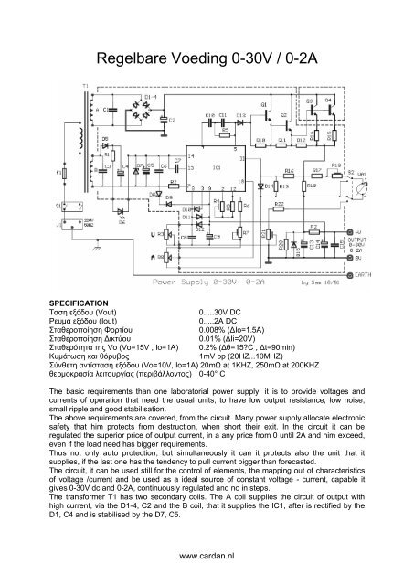
<strong>Regelbare</strong> <strong>Voeding</strong> 0-<strong>30V</strong> / 0-<strong>2A</strong><br />
SPECIFICATION<br />
Ταση εξόδου (Vout)<br />
0.....<strong>30V</strong> DC<br />
Ρευμα εξόδου (Iout)<br />
0.....<strong>2A</strong> DC<br />
Σταθεροποίηση Φορτίου<br />
0.008% (ΔΙο=1.5Α)<br />
Σταθεροποίηση Δικτύου<br />
0.01% (ΔIi=20V)<br />
Σταθερότητα της Vo (Vo=15V , Io=1A) 0.2% (Δθ=15?C , Δt=90min)<br />
Κυμάτωση και θόρυβος<br />
1mV pp (20HZ...10MHZ)<br />
Σύνθετη αντίσταση εξόδου (Vo=10V, Io=1A) 20mΩ at 1KHZ, 250mΩ at 200KHZ<br />
θερμοκρασία λειτουργίας (περιβάλλοντος) 0-40° C<br />
The basic requirements than one laboratorial power supply, it is to provide voltages and<br />
currents of operation that need the usual units, to have low output resistance, low noise,<br />
small ripple and good stabilisation.<br />
The above requirements are covered, from the circuit. Many power supply allocate electronic<br />
safety that him protects from destruction, when short their exit. In the circuit it can be<br />
regulated the superior price of output current, in a any price from 0 until <strong>2A</strong> and him exceed,<br />
even if the load need has bigger requirements.<br />
Thus not o<strong>nl</strong>y auto protection, but simultaneously it can it protects also the unit that it<br />
supplies, if the last one has the tendency to pull current bigger than forecasted.<br />
The circuit, it can be used still for the control of elements, the mapping out of characteristics<br />
of voltage /current and be used as a ideal source of constant voltage - current, capable it<br />
gives 0-<strong>30V</strong> dc and 0-<strong>2A</strong>, continuously regulated and no in steps.<br />
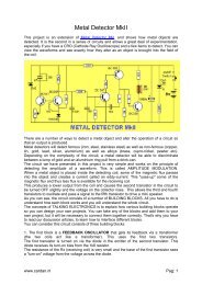
The transformer T1 has two secondary coils. The A coil supplies the circuit of output with<br />
high current, via the D1-4, C2 and the B coil, that it supplies the IC1, after is rectified by the<br />
D1, C4 and is stabilised by the D7, C5.<br />
www.cardan.<strong>nl</strong>
The current passes through LED D6, who is also useful as clue of operation. The C7 makes<br />
compensation of frequency in the internal circuit of IC1 and the R2/D8/D9, him protects from<br />
the peaks voltage of network.<br />
With R3, we regulate the output voltage, in the point that we want. With the R8, we regulate<br />
the limit of current, that we wish in the exit. In the exit of power supply exists one multiple<br />
Darlington, constituted from the Q1, Q2 and Q3, Q4 that is parallel.<br />
The Resistances R14, R15 ensure the homology of currents of collector, the R10 until R12<br />
improve the DC stability of output circuit, that has basic importance in high temperature,<br />
where the reverse currents begin to become considerable.<br />
The R9, c10, c11 achieves the compensation of frequency in the output amplifier of IC1 and<br />
the D13, his protection. Through the R19 it passes the output current. The fall of voltage that<br />
is presented in utmost his is degraded at a percentage and it is applied in the entry of 11 IC1.<br />
In the second entry of 10 IC1 is applied a constant voltage, the price of which is regulated by<br />
the R8, in the desirable biggest price of output current.<br />
As soon as the output current exceed this price, the fall of voltage in the R19, it is applied in<br />
the entry of 10 IC1, so that is activated the differential amplifier in the IC1 and it prohibits the<br />
further increase of output current.<br />
Capacitors C13, C14, C15 make unyoke of exit, while the D15 him protects from the reverse<br />
voltage. With instrument VA1, we can measure so much the output voltage, what the current,<br />
depending on the place that is placed switch S2. In the place that is appears in the circuit,<br />
the switch measure the current, taking sample from the fall of voltage, above in the R19, via<br />
the R17, R18.<br />
To we measure the voltage it will be supposed we move the switch in the other place, taking<br />
sample of output voltage. The micrometer regulation becomes from the R21, R22. The<br />
Transistor Q2, should be placed in a small heatsink, as well as the Q3, Q4, in heatsink with<br />
thermic resistance 2.6° C/W.<br />
The regulation of power supply can become easily, with the help of digital multimeter, which<br />
we will connect in the exit. Moving and regulating him trimmer in combination with main<br />
pontesometer regulation of voltage and current.<br />
Part List<br />
R1= 1.2Kohm 1W R20= 3.9Kohm D6= LED 5mm RED<br />
R2-12= 100ohm R22= 56Kohm D7= 1N5252B<br />
R3= 47Kohm Lin. C1-3= 330nF 250V D8= IN5236B<br />
R4-7-21= 10Kohm trimmer C2= 4700uF 63V<br />
D9....14= 1N4002<br />
R5= 8.2Kohm C4= 68uF 63V D15= MR501<br />
R6-10= 12Kohm C5= 47uF 40V Q1= MPSL01<br />
R8= 470ohm Lin. C6-15= 10nF 100V polyester Q2= 2N4923<br />
R9= 1.2Kohm C7-12= 100nF 100V polyester Q3-4= 2N3055<br />
R11= 820ohm C8= 680nF 100V polyester IC1= MC1466L Motorola<br />
R13= 560ohm C9-14= 1uF 40V R14-15= 0.68ohm 2W<br />
C10= 220pF ceramic F1= 1A/250V slow Fuse<br />
R16= 330ohm C11= 10pF ceramic F2= <strong>2A</strong> slow Fuse<br />
R17= 470ohm C13= 220uF 40V S1= 2XON/OFF 10A/250V<br />
R18= 470ohm trimmer D1-4= 15A Bridge S2= 2X2 ON 1A switch<br />
R19= 0.22ohm 2W D5= 1N4002 VA1= 500μA<br />
T1=220VAC/ A:34V/4A B:36V/50mA<br />
www.cardan.<strong>nl</strong>