The Official Newsletter of the - The Auckland Marklin Club Inc
The Official Newsletter of the - The Auckland Marklin Club Inc
The Official Newsletter of the - The Auckland Marklin Club Inc

You also want an ePaper? Increase the reach of your titles
YUMPU automatically turns print PDFs into web optimized ePapers that Google loves.
external wiring. <strong>The</strong> decoder receives<br />
instructions via connections to <strong>the</strong><br />
track. <strong>The</strong> same red and brown wires<br />
which provide power to <strong>the</strong> layout<br />
also provide digital information. This<br />
effectively means that you only have<br />
two wires connected to <strong>the</strong> entire<br />
layout!<br />
Keyboards attach directly to <strong>the</strong><br />
Control Unit via a port on <strong>the</strong> left<br />
hand side <strong>of</strong> <strong>the</strong> Control Unit. So a<br />
basic digital system which includes a<br />
Keyboard for accessory control looks<br />
like this:<br />
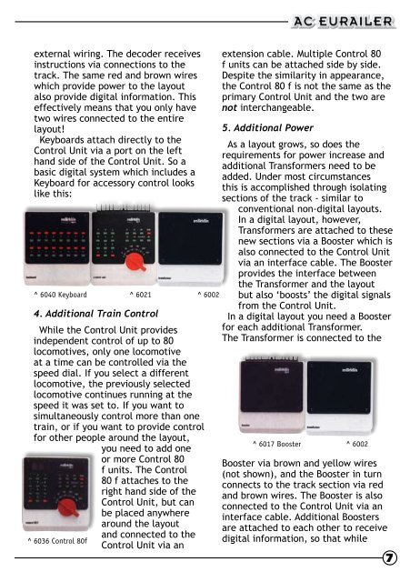
^ 6040 Keyboard ^ 6021<br />
^ 6002<br />
4. Additional Train Control<br />
While <strong>the</strong> Control Unit provides<br />
independent control <strong>of</strong> up to 80<br />
locomotives, only one locomotive<br />
at a time can be controlled via <strong>the</strong><br />
speed dial. If you select a different<br />
locomotive, <strong>the</strong> previously selected<br />
locomotive continues running at <strong>the</strong><br />
speed it was set to. If you want to<br />
simultaneously control more than one<br />
train, or if you want to provide control<br />
for o<strong>the</strong>r people around <strong>the</strong> layout,<br />
you need to add one<br />
or more Control 80<br />
f units. <strong>The</strong> Control<br />
80 f attaches to <strong>the</strong><br />
right hand side <strong>of</strong> <strong>the</strong><br />
Control Unit, but can<br />
be placed anywhere<br />
around <strong>the</strong> layout<br />
and connected to <strong>the</strong><br />
^ 6036 Control 80f<br />
Control Unit via an<br />
extension cable. Multiple Control 80<br />
f units can be attached side by side.<br />
Despite <strong>the</strong> similarity in appearance,<br />
<strong>the</strong> Control 80 f is not <strong>the</strong> same as <strong>the</strong><br />
primary Control Unit and <strong>the</strong> two are<br />
not interchangeable.<br />
5. Additional Power<br />
As a layout grows, so does <strong>the</strong><br />
requirements for power increase and<br />
additional Transformers need to be<br />
added. Under most circumstances<br />
this is accomplished through isolating<br />
sections <strong>of</strong> <strong>the</strong> track - similar to<br />
conventional non-digital layouts.<br />
In a digital layout, however,<br />
Transformers are attached to <strong>the</strong>se<br />
new sections via a Booster which is<br />
also connected to <strong>the</strong> Control Unit<br />
via an interface cable. <strong>The</strong> Booster<br />
provides <strong>the</strong> interface between<br />
<strong>the</strong> Transformer and <strong>the</strong> layout<br />
but also ‘boosts’ <strong>the</strong> digital signals<br />
from <strong>the</strong> Control Unit.<br />
In a digital layout you need a Booster<br />
for each additional Transformer.<br />
<strong>The</strong> Transformer is connected to <strong>the</strong><br />
^ 6017 Booster ^ 6002<br />
Booster via brown and yellow wires<br />
(not shown), and <strong>the</strong> Booster in turn<br />
connects to <strong>the</strong> track section via red<br />
and brown wires. <strong>The</strong> Booster is also<br />
connected to <strong>the</strong> Control Unit via an<br />
interface cable. Additional Boosters<br />
are attached to each o<strong>the</strong>r to receive<br />
digital information, so that while<br />
7