5 Series 500R11 Installation Manual - WaterFurnace
5 Series 500R11 Installation Manual - WaterFurnace
5 Series 500R11 Installation Manual - WaterFurnace

You also want an ePaper? Increase the reach of your titles
YUMPU automatically turns print PDFs into web optimized ePapers that Google loves.
5 SERIES <strong>500R11</strong> INSTALLATION MANUAL<br />
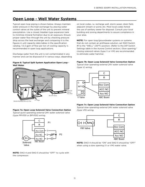
Open Loop - Well Water Systems<br />
Typical open loop piping is shown below. Always maintain<br />
water pressure in the heat exchanger by placing water<br />
control valves at the outlet of the unit to prevent mineral<br />
precipitation. Use a closed, bladder-type expansion tank<br />
to minimize mineral formation due to air exposure. Ensure<br />
proper water flow through the unit by checking pressure<br />
drop across the heat exchanger and comparing it to the<br />
figures in unit capacity data tables in the specification<br />
catalog. 1.5-2 gpm of flow per ton of cooling capacity is<br />
recommended in open loop applications.<br />
Discharge water from the unit is not contaminated in any<br />
manner and can be disposed of in various ways, depending<br />
Figure 6: Typical Split System Application Open Loop -<br />
Well Water<br />
on local codes, i.e. recharge well, storm sewer, drain field,<br />
adjacent stream or pond, etc. Most local codes forbid<br />
the use of sanitary sewer for disposal. Consult your local<br />
building and zoning departments to assure compliance in<br />
your area.<br />
NOTE: For open loop/groundwater systems or systems<br />
that do not contain an antifreeze solution, set SW2-Switch<br />
#1 to the “WELL” (30°F) position. (Refer to the DIP Switch<br />
Settings table in the Aurora Control section.) Slow opening/<br />
closing solenoid valves (type V or VM) are recommended<br />
to eliminate water hammer.<br />
Figure 7b: Open Loop Solenoid Valve Connection Option<br />
Typical slow operating external 24V water solenoid valve<br />
(type V) wiring.<br />
Thermostat Wire<br />
From Air Handler<br />
Disconnect<br />
Lineset<br />
To Air Handler<br />
Rubber Bladder<br />
Pressure Tank<br />
C<br />
R<br />
Boiler Drains for<br />
System Flushing<br />
Water Solenoid<br />
Control Valve<br />
Flow<br />
Regulator<br />
Shut-Off Valves<br />
Water Out<br />
Water In<br />
From W ell<br />
C<br />
W/Y<br />
V Valve<br />
Acc Com<br />
ACC NC<br />
Acc NO<br />
ABC Board<br />
Vibration Absorbing Pad or Air Pad<br />
P/T Plugs<br />
Figure 7a: Open Loop Solenoid Valve Connection Option<br />
Typical quick operating external 24V water solenoid valve<br />
(type PPV100 or BPV100) wiring.<br />
Figure 7c: Open Loop Solenoid Valve Connection Option<br />
Typical slow operating external 24V water solenoid valve<br />
(type VM) wiring.<br />
C<br />
C<br />
R<br />
Acc Com<br />
P1<br />
1<br />
VM Valve<br />
R<br />
Acc Com<br />
ACC NC<br />
SV<br />
Solenoid<br />
Valve<br />
Acc NC<br />
Acc NO<br />
ABC Board<br />
2<br />
3<br />
P2<br />
Acc NO<br />
ABC Board<br />
NOTE: SW2-4 should be “ON” and SW2-5 should be “OFF”<br />
when using a slow opening (V or VM) water valve.<br />
NOTE: SW2-4 and SW2-5 should be “OFF” to cycle with<br />
the compressor.<br />
11