5 Series 500R11 Installation Manual - WaterFurnace
5 Series 500R11 Installation Manual - WaterFurnace
5 Series 500R11 Installation Manual - WaterFurnace

Create successful ePaper yourself
Turn your PDF publications into a flip-book with our unique Google optimized e-Paper software.
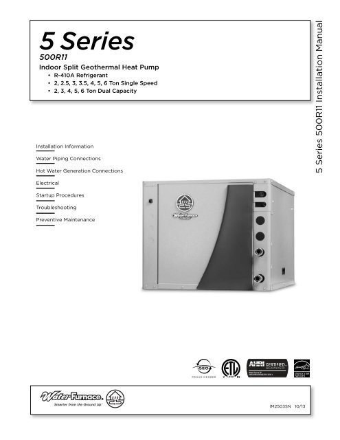
<strong>500R11</strong><br />
Indoor Split Geothermal Heat Pump<br />
• R-410A Refrigerant<br />
• 2, 2.5, 3, 3.5, 4, 5, 6 Ton Single Speed<br />
• 2, 3, 4, 5, 6 Ton Dual Capacity<br />
<strong>Installation</strong> Information<br />
Water Piping Connections<br />
Hot Water Generation Connections<br />
5 <strong>Series</strong> <strong>500R11</strong> <strong>Installation</strong> <strong>Manual</strong><br />
Electrical<br />
Startup Procedures<br />
Troubleshooting<br />
Preventive Maintenance<br />
C<br />
US<br />
IM2503SN 10/13
5 SERIES <strong>500R11</strong> INSTALLATION MANUAL<br />
Table of Contents<br />
Model Nomenclature . . . . . . . . . . . . . . . . . . . . . . . . . . . . . . . . . . . . . . . . . . . . . . . . . . . . . . . . . . . . . . 4<br />
General <strong>Installation</strong> Information . . . . . . . . . . . . . . . . . . . . . . . . . . . . . . . . . . . . . . . . . . . . . . . . . . 5-9<br />
Water Quality . . . . . . . . . . . . . . . . . . . . . . . . . . . . . . . . . . . . . . . . . . . . . . . . . . . . . . . . . . . . . . . . . . . . 9<br />
Closed Loop - Ground Source Systems . . . . . . . . . . . . . . . . . . . . . . . . . . . . . . . . . . . . . . . . . . . 10-11<br />
Open Loop - Well Water Systems . . . . . . . . . . . . . . . . . . . . . . . . . . . . . . . . . . . . . . . . . . . . . . . . . . 12<br />
Hot Water Generator Connections . . . . . . . . . . . . . . . . . . . . . . . . . . . . . . . . . . . . . . . . . . . . . . .13-14<br />
Electrical Connection. . . . . . . . . . . . . . . . . . . . . . . . . . . . . . . . . . . . . . . . . . . . . . . . . . . . . . . . . . .15-16<br />
Electronic Thermostat <strong>Installation</strong> . . . . . . . . . . . . . . . . . . . . . . . . . . . . . . . . . . . . . . . . . . . . . . .16-17<br />
Electrical Data . . . . . . . . . . . . . . . . . . . . . . . . . . . . . . . . . . . . . . . . . . . . . . . . . . . . . . . . . . . . . . . . . . . 17<br />
Dimensional Data . . . . . . . . . . . . . . . . . . . . . . . . . . . . . . . . . . . . . . . . . . . . . . . . . . . . . . . . . . . . . . . . 18<br />
Physical Data . . . . . . . . . . . . . . . . . . . . . . . . . . . . . . . . . . . . . . . . . . . . . . . . . . . . . . . . . . . . . . . . . . . . 19<br />
Model Nomenclature - Air Handler . . . . . . . . . . . . . . . . . . . . . . . . . . . . . . . . . . . . . . . . . . . . . . . . .20<br />
Coil Data - Air Handler. . . . . . . . . . . . . . . . . . . . . . . . . . . . . . . . . . . . . . . . . . . . . . . . . . . . . . . . . . . .20<br />
Compatibility Guide - Air Handler. . . . . . . . . . . . . . . . . . . . . . . . . . . . . . . . . . . . . . . . . . . . . . . . . .20<br />
Physical Data - Air Handler. . . . . . . . . . . . . . . . . . . . . . . . . . . . . . . . . . . . . . . . . . . . . . . . . . . . . . . . 21<br />
Model Nomenclature - Coil . . . . . . . . . . . . . . . . . . . . . . . . . . . . . . . . . . . . . . . . . . . . . . . . . . . . . . . . 21<br />
Refrigerant Coil Compatibility . . . . . . . . . . . . . . . . . . . . . . . . . . . . . . . . . . . . . . . . . . . . . . . . . . . . . 21<br />
The Aurora TM Control System . . . . . . . . . . . . . . . . . . . . . . . . . . . . . . . . . . . . . . . . . . . . . . . . . . . 22-27<br />
Reference Calculations . . . . . . . . . . . . . . . . . . . . . . . . . . . . . . . . . . . . . . . . . . . . . . . . . . . . . . . . . . .28<br />
Legend . . . . . . . . . . . . . . . . . . . . . . . . . . . . . . . . . . . . . . . . . . . . . . . . . . . . . . . . . . . . . . . . . . . . . . . . .28<br />
Wiring Schematics . . . . . . . . . . . . . . . . . . . . . . . . . . . . . . . . . . . . . . . . . . . . . . . . . . . . . . . . . . . .29-30<br />
Refrigeration . . . . . . . . . . . . . . . . . . . . . . . . . . . . . . . . . . . . . . . . . . . . . . . . . . . . . . . . . . . . . . . . . 31-33<br />
Line Set Sizes . . . . . . . . . . . . . . . . . . . . . . . . . . . . . . . . . . . . . . . . . . . . . . . . . . . . . . . . . . . . . . . . . . .33<br />
Pressure/Temperature Conversion Chart for R-410A . . . . . . . . . . . . . . . . . . . . . . . . . . . . . . . . .34<br />
Unit Startup . . . . . . . . . . . . . . . . . . . . . . . . . . . . . . . . . . . . . . . . . . . . . . . . . . . . . . . . . . . . . . . . . . 35-37<br />
Operating Parameters . . . . . . . . . . . . . . . . . . . . . . . . . . . . . . . . . . . . . . . . . . . . . . . . . . . . . . . . .38-39<br />
Pressure Drop . . . . . . . . . . . . . . . . . . . . . . . . . . . . . . . . . . . . . . . . . . . . . . . . . . . . . . . . . . . . . . . . . . 40<br />
Refrigerant Circuit Guideline . . . . . . . . . . . . . . . . . . . . . . . . . . . . . . . . . . . . . . . . . . . . . . . . . . . . . . 41<br />
Thermistor Resistance . . . . . . . . . . . . . . . . . . . . . . . . . . . . . . . . . . . . . . . . . . . . . . . . . . . . . . . . . . . . 41<br />
Heat of Extraction/Rejection Data . . . . . . . . . . . . . . . . . . . . . . . . . . . . . . . . . . . . . . . . . . . . . . . . .42<br />
Troubleshooting . . . . . . . . . . . . . . . . . . . . . . . . . . . . . . . . . . . . . . . . . . . . . . . . . . . . . . . . . . . . . .43-45<br />
Preventative Maintenance. . . . . . . . . . . . . . . . . . . . . . . . . . . . . . . . . . . . . . . . . . . . . . . . . . . . . . . . .46<br />
Replacement Procedures . . . . . . . . . . . . . . . . . . . . . . . . . . . . . . . . . . . . . . . . . . . . . . . . . . . . . . . . .46<br />
Service Parts List . . . . . . . . . . . . . . . . . . . . . . . . . . . . . . . . . . . . . . . . . . . . . . . . . . . . . . . . . . . . . . . .47<br />
Revision Guide. . . . . . . . . . . . . . . . . . . . . . . . . . . . . . . . . . . . . . . . . . . . . . . . . . . . . . . . . . . . . . . . . . .49
5 SERIES <strong>500R11</strong> INSTALLATION MANUAL<br />
Model Nomenclature<br />
1 2 3 4-6 7 8 9 10 11 12 13 14 15<br />
N D Z 049 * 1 1 0 C N N 0 A<br />
16<br />
A<br />
Model<br />
N – 5 <strong>Series</strong><br />
Stage<br />
D – Dual Capacity<br />
S – Single Capacity<br />
Cabinet Configuration<br />
Z – Indoor Split<br />
Unit Capacity<br />
022, 026, 030, 036, 038,<br />
042, 048, 049, 060, 064,<br />
070, 072<br />
Vintage<br />
* - Factory Use Only<br />
Voltage<br />
1 – 208-230/60/1<br />
Hot Water Generation<br />
0 – None<br />
1 – Hot Water Generation with Factory Installed Pump<br />
IntelliStart Option<br />
N – None<br />
A - IntelliStart<br />
Controls<br />
A – Aurora TM Base Control (ABC)<br />
Future Options<br />
0 – None<br />
Future Options<br />
N – None<br />
Future Options<br />
N – None<br />
Water Coax Option<br />
C – Copper<br />
N – CuproNickel<br />
Future Option<br />
0 - None<br />
Rev.: 06 June 2013D<br />
4
5 SERIES <strong>500R11</strong> INSTALLATION MANUAL<br />
General <strong>Installation</strong> Information<br />
Safety Considerations<br />
WARNING: Before performing service or<br />
maintenance operations on a system, turn off main<br />
power switches to the indoor unit. If applicable,<br />
turn off the accessory heater power switch.<br />
Electrical shock could cause personal injury.<br />
Installing and servicing heating and air conditioning<br />
equipment can be hazardous due to system pressure and<br />
electrical components. Only trained and qualified service<br />
personnel should install, repair or service heating and air<br />
conditioning equipment. Untrained personnel can perform<br />
the basic maintenance functions of cleaning coils and<br />
cleaning and replacing filters. All other operations should be<br />
performed by trained service personnel. When working on<br />
heating and air conditioning equipment, observe precautions<br />
in the literature, tags and labels attached to the unit and<br />
other safety precautions that may apply, such as the<br />
following safety measures:<br />
• Follow all safety codes.<br />
• Wear safety glasses and work gloves.<br />
• Use a quenching cloth for brazing operations.<br />
• Have a fire extinguisher available for all brazing operations.<br />
Moving and Storage<br />
Move units in the normal “up” orientation. Units may be<br />
moved and stored per the information on the packaging.<br />
Do not stack more than three units in total height. Do not<br />
attempt to move units while stacked. When the equipment<br />
is received, all items should be carefully checked against<br />
the bill of lading to be sure all crates and cartons have been<br />
received. Examine units for shipping damage, removing<br />
the units from the packaging if necessary. Units in question<br />
should also be internally inspected. If any damage is noted,<br />
the carrier should make the proper notation on the delivery<br />
receipt, acknowledging the damage.<br />
Unit Location<br />
NOTE: Prior to setting the unit in place, remove and discard<br />
the compressor shipping bolt located at the front of the<br />
compressor mounting bracket.<br />
Locate the unit in an indoor area that allows for easy<br />
removal of the access panels. Location should have enough<br />
space for service personnel to perform maintenance or<br />
repair. Provide sufficient room to make water, electrical and<br />
refrigerant line connections. Any access panel screws that<br />
would be difficult to remove after the unit is installed should<br />
be removed prior to setting the unit. Care should be taken<br />
when units are located in unconditioned spaces to prevent<br />
damage from frozen water lines and excessive heat that<br />
could damage electrical components.<br />
Air Coil Location<br />
Refer to the air handler manufacturer’s instructions for the<br />
blower coil unit for details on installing the air handling<br />
portion of the system.<br />
Condensate Drain<br />
Follow the blower coil manufacturer’s instructions.<br />
Duct System<br />
All blower coil units/air coils must be installed as specified<br />
by the manufacturer’s installation instructions; however,<br />
the following recommendations should be considered to<br />
minimize noise and service problems.<br />
An air filter must always be installed upstream of the air coil<br />
on the return air side of the air handler or furnace. If there<br />
is limited access to the filter rack for normal maintenance, it<br />
is suggested that a return air filter grill be installed. Be sure<br />
that the return duct is properly installed and free of leaks<br />
to prevent dirt and debris from bypassing the filter and<br />
plugging the air coil.<br />
In applications using galvanized metal ductwork, a flexible<br />
duct connector is recommended on both the supply and<br />
return air plenums to minimize vibration from the blower. To<br />
maximize sound attenuation of the unit blower, the supply<br />
and return plenums should include an internal duct liner<br />
of 1-inch thick glass fiber or be constructed of ductboard.<br />
Insulation is usually not installed in the supply branch ducts.<br />
Ducts in unconditioned areas should be wrapped with a<br />
minimum of 1-inch duct insulation. Application of the unit<br />
to uninsulated ductwork in an unconditioned space is not<br />
recommended as the unit’s performance will be adversely<br />
affected. If the air handler is connected to existing ductwork,<br />
a previous check should have been made to assure that the<br />
duct system has the capacity to handle the air required for<br />
the unit application. If ducting is too small, as in replacement<br />
of heating only systems, larger ductwork should be installed.<br />
All existing ductwork should be checked for leaks and<br />
repairs made accordingly. The duct systems and diffusers<br />
should be sized to handle the design airflow quietly. If air<br />
noise or excessive airflow is a problem, the blower speed<br />
can be changed to a lower speed to reduce airflow. This<br />
will reduce the performance of the unit slightly in heating;<br />
however, it will increase the temperature rise across the air<br />
coil. Airflow must still meet minimum requirements.<br />
Equipment Selection<br />
The following guidelines should be used when mating a 5<br />
<strong>Series</strong> Split to an air handler/coil.<br />
• Select R-410A components only.<br />
• Select 13 SEER or higher air handler/coil.<br />
• Match the air handler to the air handler coil data table.<br />
• Indoor matching adjustable TXV should be used with<br />
any air handler/coil. Fixed orifice or cap tube systems<br />
should not be used.<br />
Utilizing Existing Coil or Air Handler<br />
It is recommended that a new R-410A air handler be<br />
installed with a 5 <strong>Series</strong> Split considering the long term<br />
benefits of reliability, warranty, etc. versus the short term<br />
installation cost savings. However, the existing air handler<br />
may be retained provided the following:<br />
• Coil currently is R-410A rated<br />
• Coil uses a TXV. No capillary or fixed orifice systems<br />
should be used<br />
• A life expectancy of more than 7 years remaining for the<br />
air handler and components<br />
• Flush air coil and line set<br />
5
5 SERIES <strong>500R11</strong> INSTALLATION MANUAL<br />
General <strong>Installation</strong> Information cont.<br />
When utilizing the existing air coil or line set, only flushing<br />
compounds that vaporize should be used; which means<br />
they are packaged in a pressurized disposable cylinder. It is<br />
preferable to use a flushing agent that removes oil, water,<br />
and acid, plus, is biodegradeable and non-toxic. The flushing<br />
agent should be safe to use with both HCFC and HFC<br />
refrigerants. Once a flushing agent has been selected, follow<br />
the instructions provided with the product.<br />
The first step should be purging the lines or air coil with<br />
nitrogen. Purging with nitrogen first will remove some of<br />
the particulate and residual oil which will allow the flushing<br />
agent to work better. Never blow the flushing agent<br />
through a compressor, filter drier, or txv as it will cause the<br />
components to fail.<br />
When flushing is complete and the final system is assembled,<br />
an acid check should be preformed on the system. Acid test<br />
kits are available from most HVACR distributors.<br />
Connection to Air Coil<br />
Figures 1 and 2 illustrate typical 5 <strong>Series</strong> Split installations.<br />
Reference the Line Set Sizes table for typical line set<br />
diameters and maximum length. Line sets over 60 feet are<br />
not recommended. Longer line sets will significantly reduce<br />
capacity and efficiency of the system as well as adversely<br />
effect the system reliability due to poor oil return. If the<br />
line set is kinked or deformed and cannot be reformed, the<br />
bad section of pipe should be replaced. A restricted line set<br />
will affect unit performance. As in all R-410A equipment,<br />
a reversible liquid line filter drier is required to insure all<br />
moisture is removed from the system. This drier should be<br />
replaced whenever “breaking into” the system for service. All<br />
line sets should be insulated with a minimum of 1/2 in. closed<br />
cell insulation. All exterior insulation should be painted with<br />
UV resistant paint or covering to ensure long insulation life.<br />
Air Handler <strong>Installation</strong><br />
Air handlers used with dual capacity units must be capable<br />
of operating with a minimum of 2 blower speeds. Refer to<br />
the manufacturer’s instructions for the blower coil unit for<br />
details on installing the air handling portion of the system.<br />
All blower coil units/air coils must be installed as specified<br />
by the manufacturer’s installations instructions. However,<br />
the following recommendations should be considered to<br />
minimize noise and service problems.<br />
An air filter must always be installed upstream of the air coil<br />
on the return air side of the air handler or furnace. If there<br />
is limited access to the filter rack for normal maintenance,<br />
it is suggested that a return air filter grille be installed. Be<br />
sure that the return duct is properly installed and free of<br />
leaks to prevent dirt and debris from bypassing the filter and<br />
plugging the air coil.<br />
Ensure that the line set size is appropriate to the capacity of<br />
the unit (refer to Line Set Sizes table). Line sets should be<br />
routed as directly as possible, avoiding unnecessary bends<br />
or turns. All wall penetrations should be sealed properly. Line<br />
set should not come into direct contact with water pipes,<br />
floor joists, wall studs, duct work, floors, walls and brick.<br />
Line set should not be suspended from joists or studs with a<br />
rigid wire or strap which comes into direct contact with the<br />
tubing. Wide hanger strips which conform to the shape of<br />
the tubing are recommended. Isolate hanger straps from line<br />
set insulation by using metal sleeves bent to conform to the<br />
shape of insulation. Line set insulation should be pliable, and<br />
should completely surround the refrigerant line.<br />
NOTES: Improper installation of equipment may result in<br />
undesirable noise levels in the living areas.<br />
Figure 1: Typical Split System Application with Remote Blower Coil<br />
Thermostat Wire<br />
From Air Handler<br />
Supply<br />
Duct<br />
Wire To<br />
Thermostat<br />
Disconnect<br />
Insulated Suction Line<br />
Return<br />
Duct<br />
Lineset To Air Handler<br />
To Drain<br />
DHW Out<br />
DHW In<br />
Remote Air Handler<br />
(Maximum Recommended Distance is<br />
60' Between Units)<br />
Condensate Drain<br />
(must be trapped)<br />
P/T Plugs<br />
Water Out<br />
Water In<br />
Vibration Absorbing Pad or Air Pad<br />
6
5 SERIES <strong>500R11</strong> INSTALLATION MANUAL<br />
General <strong>Installation</strong> Information cont.<br />
Dual Fuel Systems<br />
5 <strong>Series</strong> units can be connected to fossil fuel furnaces that<br />
include an A-coil or slab coil. Dual fuel installations utilize<br />
the 5 <strong>Series</strong> heat pump for heating until the point that<br />
auxiliary heat is called for on the thermostat. At that point,<br />
the furnace will be enabled and the heat pump will be<br />
disabled. The 5 <strong>Series</strong> heat pump provides air conditioning<br />
through the furnace’s refrigerant coils.<br />
Refer to the furnace manufacturer’s installation manual<br />
for the furnace installation, wiring and coil insertion. A<br />
<strong>WaterFurnace</strong> Dual Fuel thermostat, a field-installed SPST<br />
relay or dual capacity auxiliary heat relay is required. See<br />
Figure 2 for typical Dual Fuel application.<br />
In add-on 5 <strong>Series</strong> Split applications, the coil should<br />
be located in the supply side of the furnace to avoid<br />
condensation damage to the furnace heat exchanger. A<br />
high temperature limit should be installed upstream of the<br />
coil to de-energize the compressor whenever the furnace<br />
is operating. Without this switch, the 5 <strong>Series</strong> Split will trip<br />
out on high pressure. A dual fuel thermostat can remove<br />
the Y1 and Y2 calls when a W call is energized to allow gas<br />
furnace backup on a 5 <strong>Series</strong> Split application. Refer to<br />
thermostat wiring diagram for details.<br />
Figure 2: Typical Split System Heat Pump Coil Add-On Fossil Fuel Furnace<br />
Maximum Recommended Distance<br />
is 60' Between Units<br />
"A" or<br />
Slab Coil<br />
Supply Duct<br />
Air Temperature Limit Switch -<br />
to prevent compressor operation<br />
when entering air is greater than<br />
90°F.<br />
Wire To<br />
Thermostat<br />
Disconnect<br />
Insulated Suction Line<br />
Lineset To Air Handler<br />
Thermostat<br />
Wire From<br />
Air Handler<br />
Condensate<br />
Drain<br />
(must be trapped)<br />
DHW Out<br />
DHW In<br />
P/T Plugs<br />
Water Out<br />
Water In<br />
Return<br />
Duct<br />
Vibration Absorbing Pad or Air Pad<br />
Up-Flow<br />
Fossil Fuel<br />
Furnace<br />
7
5 SERIES <strong>500R11</strong> INSTALLATION MANUAL<br />
General <strong>Installation</strong> Information cont.<br />
Water Piping<br />
The proper water flow must be provided to each unit<br />
whenever the unit operates. To assure proper flow, use<br />
pressure/temperature ports to determine the flow rate.<br />
These ports should be located at the supply and return<br />
water connections on the unit. The proper flow rate cannot<br />
be accurately set without measuring the water pressure<br />
drop through the refrigerant-to-water heat exchanger.<br />
Never use flexible hoses smaller than 1 in. inside diameter<br />
on the unit. Limit hose length to 10 ft. per connection.<br />
Check carefully for water leaks.<br />
Figure 3: Swivel Connections<br />
(Residential Units)<br />
All source water connections on residential units are<br />
swivel piping fittings (see Figure 3) that accept 1 in. male<br />
pipe threads (MPT). The swivel connector has a rubber<br />
gasket seal similar to a rubber hose gasket, which when<br />
mated to the flush end of any 1 in. threaded pipe provides<br />
a leak-free seal without the need for thread sealing tape<br />
or compound. Check to ensure that the rubber seal is in<br />
the swivel connector prior to attempting any connection.<br />
The rubber seals are shipped attached to the waterline.<br />
To make the connection to a ground loop system, mate<br />
the brass connector (supplied in CK4L connector kit)<br />
against the rubber gasket in the swivel connector and<br />
thread the female locking ring onto the pipe threads, while<br />
maintaining the brass connector in the desired direction.<br />
Tighten the connectors by hand, then gently snug the<br />
fitting with pliers to provide a leak-proof joint. When<br />
connecting to an open loop (ground water) system, thread<br />
the 1 in. MPT fitting (SCH80 PVC or copper) into the swivel<br />
connector and tighten in the same manner as noted above.<br />
The open and closed loop piping system should include<br />
pressure/temperature taps for serviceability.<br />
Stainless<br />
Steel<br />
Snap Ring<br />
Gasket<br />
Material<br />
Locking<br />
Ring<br />
Gasket<br />
Support<br />
Sleeve<br />
8
5 SERIES <strong>500R11</strong> INSTALLATION MANUAL<br />
General <strong>Installation</strong> Information cont.<br />
Water Quality<br />
In ground water situations where scaling could be heavy<br />
or where biological growth such as iron bacteria will be<br />
present, a closed loop system is recommended. The heat<br />
exchanger coils in ground water systems may, over a period<br />
of time, lose heat exchange capabilities due to a buildup<br />
of mineral deposits inside. These can be cleaned, but only<br />
by a qualified service mechanic, as special solutions and<br />
pumping equipment are required. Hot water generator coils<br />
can likewise become scaled and possibly plugged. In areas<br />
with extremely hard water, the owner should be informed<br />
that the heat exchanger may require occasional flushing.<br />
Units with cupronickel heat exchangers are recommended<br />
for open loop applications due to the increased resistance<br />
to build-up and corrosion, along with reduced wear caused<br />
by acid cleaning. Failure to adhere to the guidelines in the<br />
water quality table could result in the loss of warranty.<br />
Material Copper 90/10 Cupronickel 316 Stainless Steel<br />
pH Acidity/Alkalinity 7 - 9 7 - 9 7 - 9<br />
Scaling<br />
Calcium and<br />
(Total Hardness)<br />
(Total Hardness)<br />
(Total Hardness)<br />
Magnesium Carbonate<br />
less than 350 ppm<br />
less than 350 ppm<br />
less than 350 ppm<br />
Hydrogen Sulfide<br />
Less than 0.5 ppm (rotten egg<br />
smell appears at 0.5 ppm)<br />
10 - 50 ppm Less than 1 ppm<br />
Sulfates Less than 125 ppm Less than 125 ppm Less than 200 ppm<br />
Chlorine Less than 0.5 ppm Less than 0.5 ppm Less than 0.5 ppm<br />
Chlorides Less than 20 ppm Less than 125 ppm Less than 300 ppm<br />
Carbon Dioxide Less than 50 ppm 10 - 50 ppm 10 - 50 ppm<br />
Corrosion<br />
Ammonia Less than 2 ppm Less than 2 ppm Less than 20 ppm<br />
Ammonia Chloride Less than 0.5 ppm Less than 0.5 ppm Less than 0.5 ppm<br />
Ammonia Nitrate Less than 0.5 ppm Less than 0.5 ppm Less than 0.5 ppm<br />
Ammonia Hydroxide Less than 0.5 ppm Less than 0.5 ppm Less than 0.5 ppm<br />
Ammonia Sulfate Less than 0.5 ppm Less than 0.5 ppm Less than 0.5 ppm<br />
Total Dissolved Solids (TDS) Less than 1000 ppm 1000 - 1500 ppm 1000 - 1500 ppm<br />
LSI Index +0.5 to -0.5 +0.5 to -0.5 +0.5 to -0.5<br />
Iron, FE 2 + (Ferrous)<br />
Iron Fouling Bacterial Iron Potential<br />
< 0.2 ppm < 0.2 ppm < 0.2 ppm<br />
(Biological Growth)<br />
Less than 1 ppm, above this Less than 1 ppm, above this Less than 1 ppm, above this<br />
Iron Oxide<br />
level deposition will occur level deposition will occur level deposition will occur<br />
Suspended Solids<br />
Erosion<br />
Threshold Velocity<br />
(Fresh Water)<br />
NOTES: Grains = ppm divided by 17<br />
mg/L is equivalent to ppm<br />
Less than 10 ppm and filtered<br />
for max. of 600 micron size<br />
Less than 10 ppm and filtered<br />
for max. of 600 micron size<br />
Less than 10 ppm and filtered<br />
for max. of 600 micron size<br />
< 6 ft/sec < 6 ft/sec < 6 ft/sec<br />
2/22/12<br />
Low Water Coil Limit<br />
Set the freeze sensing switch SW2-1 on the Aurora Base<br />
Control (ABC) printed circuit board for applications using<br />
a closed loop antifreeze solution to “LOOP” (15°F). On<br />
applications using an open loop/ground water system (or<br />
closed loop no antifreeze), set this dip switch to “WELL”<br />
(30°F), the factory default setting. (Refer to the DIP Switch<br />
Settings table in the Aurora Control section.)<br />
9
5 SERIES <strong>500R11</strong> INSTALLATION MANUAL<br />
Closed Loop - Ground Source Systems<br />
NOTE: For closed loop systems with antifreeze protection,<br />
set SW2-1 to the “LOOP” (15°F) position. (Refer to the DIP<br />
Switch Settings table in the Aurora Control section.)<br />
Once piping is completed between the unit, pumps and the<br />
ground loop (see figure below), final purging and charging<br />
of the loop is required. A flush cart (or a 1.5 HP pump<br />
minimum) is needed to achieve adequate flow velocity in<br />
the loop to purge air and dirt particles from the loop itself.<br />
Antifreeze solution is used in most areas to prevent freezing.<br />
Flush the system adequately to remove as much air<br />
as possible then pressurize the loop to a static pressure of<br />
40-50 psi (summer) or 50-75 psi (winter). This is normally<br />
adequate for good system operation. Loop static pressure<br />
will fluctuate with the seasons. Pressures will be higher in<br />
the winter months than during the cooling season. This fluctuation<br />
is normal and should be considered when initially<br />
charging the system.<br />
After pressurization, be sure to turn the venting (burping)<br />
screw in the center of the pump two (2) turns open (water<br />
will drip out), wait until all air is purged from the pump,<br />
then tighten the plug. Ensure that the loop pumps provide<br />
adequate flow through the unit(s) by checking the pressure<br />
drop across the heat exchanger and comparing it to the unit<br />
capacity data in this catalog. 2.5 to 3 gpm of flow per ton of<br />
cooling capacity is recommended in earth loop applications.<br />
Multiple Units on One Flow Center<br />
When two units are connected to one loop pumping system,<br />
pump control is achieved by following Figure 5. Installer will<br />
be required to supply fuses, two relays, and wiring.<br />
Figure 5: Primary/Secondary Wiring<br />
Ext Pump<br />
1/2 hp Total<br />
208-230/60/1<br />
Pump<br />
G<br />
Pump<br />
PB1<br />
1<br />
1<br />
2<br />
2<br />
Circuit<br />
Breaker<br />
5A<br />
5A<br />
Circuit<br />
Breaker<br />
Field Supplied<br />
Relay for Heat<br />
Pump 2<br />
Hot Water<br />
Limit Switch<br />
130°F<br />
Purple<br />
HWG<br />
Pump<br />
Cabinet<br />
HW Switch<br />
Blue<br />
3<br />
1 2<br />
Optional Internal<br />
HWG Pump<br />
Field Supplied<br />
Fuses 5A<br />
Cap<br />
Blue<br />
Tan(6)<br />
Field Supplied<br />
Relay for Heat<br />
Pump 1<br />
S<br />
T2<br />
L2<br />
Red<br />
C<br />
R<br />
T1<br />
CC<br />
Compressor<br />
Black<br />
L1<br />
Heat Pump 1<br />
Contactor Coil<br />
Heat Pump 2<br />
Contactor Coil<br />
Figure 4: Typical Split System Application Closed Loop - Earth Coupled<br />
Thermostat Wire<br />
From Air Handler<br />
Disconnect<br />
Insulated<br />
To Loop<br />
GeoLink<br />
Flow Center<br />
Flow Center<br />
Electrical Supply<br />
Lineset<br />
To Air<br />
Handler<br />
DHW Out<br />
DHW In<br />
Water Out<br />
Rubber Hose Connector<br />
Kit CK4L or CK4S<br />
Vibration Absorbing Pad or Air Pad<br />
P/T Plugs<br />
Water In<br />
NOTE: Additional information can be found in Flow<br />
Center installation manual and Flush Cart manual.<br />
10
5 SERIES <strong>500R11</strong> INSTALLATION MANUAL<br />
Open Loop - Well Water Systems<br />
Typical open loop piping is shown below. Always maintain<br />
water pressure in the heat exchanger by placing water<br />
control valves at the outlet of the unit to prevent mineral<br />
precipitation. Use a closed, bladder-type expansion tank<br />
to minimize mineral formation due to air exposure. Ensure<br />
proper water flow through the unit by checking pressure<br />
drop across the heat exchanger and comparing it to the<br />
figures in unit capacity data tables in the specification<br />
catalog. 1.5-2 gpm of flow per ton of cooling capacity is<br />
recommended in open loop applications.<br />
Discharge water from the unit is not contaminated in any<br />
manner and can be disposed of in various ways, depending<br />
Figure 6: Typical Split System Application Open Loop -<br />
Well Water<br />
on local codes, i.e. recharge well, storm sewer, drain field,<br />
adjacent stream or pond, etc. Most local codes forbid<br />
the use of sanitary sewer for disposal. Consult your local<br />
building and zoning departments to assure compliance in<br />
your area.<br />
NOTE: For open loop/groundwater systems or systems<br />
that do not contain an antifreeze solution, set SW2-Switch<br />
#1 to the “WELL” (30°F) position. (Refer to the DIP Switch<br />
Settings table in the Aurora Control section.) Slow opening/<br />
closing solenoid valves (type V or VM) are recommended<br />
to eliminate water hammer.<br />
Figure 7b: Open Loop Solenoid Valve Connection Option<br />
Typical slow operating external 24V water solenoid valve<br />
(type V) wiring.<br />
Thermostat Wire<br />
From Air Handler<br />
Disconnect<br />
Lineset<br />
To Air Handler<br />
Rubber Bladder<br />
Pressure Tank<br />
C<br />
R<br />
Boiler Drains for<br />
System Flushing<br />
Water Solenoid<br />
Control Valve<br />
Flow<br />
Regulator<br />
Shut-Off Valves<br />
Water Out<br />
Water In<br />
From W ell<br />
C<br />
W/Y<br />
V Valve<br />
Acc Com<br />
ACC NC<br />
Acc NO<br />
ABC Board<br />
Vibration Absorbing Pad or Air Pad<br />
P/T Plugs<br />
Figure 7a: Open Loop Solenoid Valve Connection Option<br />
Typical quick operating external 24V water solenoid valve<br />
(type PPV100 or BPV100) wiring.<br />
Figure 7c: Open Loop Solenoid Valve Connection Option<br />
Typical slow operating external 24V water solenoid valve<br />
(type VM) wiring.<br />
C<br />
C<br />
R<br />
Acc Com<br />
P1<br />
1<br />
VM Valve<br />
R<br />
Acc Com<br />
ACC NC<br />
SV<br />
Solenoid<br />
Valve<br />
Acc NC<br />
Acc NO<br />
ABC Board<br />
2<br />
3<br />
P2<br />
Acc NO<br />
ABC Board<br />
NOTE: SW2-4 should be “ON” and SW2-5 should be “OFF”<br />
when using a slow opening (V or VM) water valve.<br />
NOTE: SW2-4 and SW2-5 should be “OFF” to cycle with<br />
the compressor.<br />
11
5 SERIES <strong>500R11</strong> INSTALLATION MANUAL<br />
Hot Water Generator Connections<br />
The heat reclaiming hot water generator coil is vented<br />
double-wall copper construction and is suitable for potable<br />
water. To maximize the benefits of the hot water generator<br />
a minimum 50-gallon water heater is recommended. For<br />
higher demand applications, use an 80-gallon water heater<br />
or two 50-gallon water heaters connected in a series as<br />
shown below. A geo storage tank should not be used in this<br />
application unless it is plumbed in a series with an electric<br />
water heater. The geo storage tank is equipped with a<br />
single 4500 Watt element and will not be able to provide<br />
adequate water heating if used as a standalone water<br />
heater. Electric water heaters are recommended. Make sure<br />
all local electrical and plumbing codes are followed when<br />
installing a hot water generator. Residential units with hot<br />
water generators contain an internal circulator and fittings. A<br />
water softener is recommended for hard water applications<br />
(greater than 10 grains or 170 ppm total hardness).<br />
Water Tank Preparation<br />
To install a unit with hot water generator, follow these<br />
installation guidelines.<br />
1. Turn off the power to the water heater.<br />
2. Attach a water hose to the water tank drain<br />
connection and run the other end of the hose to an<br />
open drain or outdoors.<br />
3. Close the cold water inlet valve to the water heater tank.<br />
4. Drain the tank by opening the valve on the bottom<br />
of the tank, then open the pressure relief valve or hot<br />
water faucet.<br />
5. Flush the tank by opening the cold water inlet valve to<br />
the water heater to free the tank of sediments. Close<br />
when draining water is clear.<br />
6. Disconnect the garden hose and remove the drain<br />
valve from the water heater.<br />
7. Refer to Plumbing <strong>Installation</strong> and Hot Water<br />
Generator Startup.<br />
CAUTION: Elements will burn out if energized dry.<br />
Figure 8: Typical Hot Water Generator <strong>Installation</strong><br />
Venting Waste Valve<br />
or Vent Coupling<br />
<br />
Cold<br />
Water In<br />
Hot<br />
Water Out<br />
Figure 9: Hot Water Generator <strong>Installation</strong> in<br />
Preheat Tank<br />
<br />
Venting Waste Valve<br />
or Vent Coupling<br />
Cold<br />
Water In<br />
Hot<br />
Water Out<br />
HWG<br />
Water Out<br />
P/T Relief<br />
Valv e<br />
HWG<br />
Water Out<br />
P/T Relief<br />
Valve<br />
P/T Relief<br />
Valve<br />
In<br />
In<br />
HWG<br />
Water In<br />
Drain Valve<br />
HWG<br />
Water In<br />
Drain Valve<br />
Drain Valve<br />
12
5 SERIES <strong>500R11</strong> INSTALLATION MANUAL<br />
Hot Water Generator Connections cont.<br />
Plumbing <strong>Installation</strong><br />
1. Inspect the dip tube in the water heater cold inlet for a<br />
check valve. If a check valve is present it must be removed<br />
or damage to the hot water generator circulator<br />
will occur.<br />
2. Remove drain valve and fitting.<br />
3. Thread the 3/4-inch NPT x 3-1/2-inch brass nipple into<br />
the water heater drain port.<br />
4. Attach the center port of the 3/4-inch FPT tee to the<br />
opposite end of the brass nipple.<br />
5. Attach the 1/2-inch copper to 3/4-inch NPT adaptor to<br />
the side of the tee closest to the unit.<br />
6. Install the drain valve on the tee opposite the adaptor.<br />
7. Run interconnecting tubing from the tee to hot water<br />
generator water out.<br />
8. Cut the cold water “IN” line going to the water heater.<br />
9. Insert the reducing solder tee in line with cold water<br />
“IN” line as shown.<br />
10. Run interconnecting copper tubing between the unit hot<br />
water generator water “IN” and the tee (1/2-inch nominal).<br />
The recommended maximum distance is 50 feet.<br />
11. To prevent air entrapment in the system, install a vent<br />
coupling at the highest point of the interconnecting lines.<br />
12. Insulate all exposed surfaces of both connecting water<br />
lines with 3/8-inch wall closed cell insulation.<br />
NOTE: All plumbing and piping connections must comply<br />
with local plumbing codes.<br />
Hot Water Generator Switch<br />
The hot water generator switch is taped in the disabled<br />
position at the factory.<br />
Hot Water Generator Startup<br />
1. Turn the hot water generator switch to the “ON” position.<br />
The hot water generator switch will allow the hot<br />
water generator pump to be enabled or disabled by the<br />
service technician or homeowner.<br />
2. Close the drain valve to the water heater.<br />
3. Open the cold water supply to the tank.<br />
4. Open a hot water faucet in the building to bleed air from<br />
the system. Close when full.<br />
5. Open the pressure relief valve to bleed any remaining air<br />
from the tank, then close.<br />
6. If so equipped, turn the venting (burping) screw in the<br />
center of the pump two (2) turns open (water will drip<br />
out), wait until all air is purged from the pump, then<br />
tighten the plug. Use vent couplings to bleed air from<br />
the lines.<br />
7. Carefully inspect all plumbing for water leaks and correct<br />
as required.<br />
8. Before restoring electrical supply to the water heater,<br />
adjust the temperature setting on the tank.<br />
• On tanks with both upper and lower elements,<br />
the lower element should be turned down to<br />
the lowest setting, approximately 100°F. The<br />
upper element should be adjusted to 120°F to<br />
130°F. Depending upon the specific needs of the<br />
customer, you may want to adjust the upper element<br />
differently.<br />
• On tanks with a single element, lower the thermostat<br />
setting to 120°F.<br />
9. After the thermostat(s) is adjusted, replace the access<br />
cover and restore electrical supply to the water heater.<br />
10. Make sure that any valves in the hot water generator<br />
water circulating circuit are open.<br />
11. Turn on the unit to first stage heating.<br />
12. The hot water generator pump should be running. When<br />
the pump is first started, turn the venting (burping)<br />
screw (if equipped) in the center of the pump two (2)<br />
turns open until water dribbles out, then replace. Allow<br />
the pump to run for at least five minutes to ensure<br />
that water has filled the circulator properly. Be sure the<br />
switch for the hot water generator pump switch is “ON”.<br />
13. The temperature difference between the water entering<br />
and leaving the hot water generator should be 5°F to<br />
15°F. The water flow should be approximately 0.4 gpm<br />
per ton of nominal cooling.<br />
14. Allow the unit to heat water for 15 to 20 minutes to be<br />
sure operation is normal.<br />
CAUTION: Never operate the HWG circulating<br />
pump while dry. If the unit is placed in operation<br />
before the hot water generator piping is<br />
connected, be sure that the pump switch is set<br />
to the OFF position.<br />
13
5 SERIES <strong>500R11</strong> INSTALLATION MANUAL<br />
Electrical Connections<br />
General<br />
Be sure the available power is the same voltage and phase<br />
as that shown on the unit serial plate. Line and low voltage<br />
wiring must be done in accordance with local codes or the<br />
National Electric Code, whichever is applicable.<br />
Unit Power Connection<br />
Connect the incoming line voltage wires to L1 and L2 of<br />
the contactor as shown in Figure 10C for single-phase unit.<br />
Consult the Unit Electrical Data in this manual for correct<br />
fuse sizes.<br />
Open lower front access panel. Remove ground fastener<br />
from bottom of control box (Figure 10B). Swing open<br />
control box (Figure 10A). Insert power wires through<br />
knockouts on lower left side of cabinet. Route wires<br />
through left side of control box and connect to contactor<br />
and ground (Figure 10C). Close control box and replace<br />
grounding fastener before unit start-up.<br />
Accessory Relay<br />
A set of “dry” contacts has been provided to control<br />
accessory devices, such as water solenoid valves on open<br />
loop installations, electronic air cleaners, humidifiers, etc.<br />
This relay contact should be used only with 24 volt signals<br />
and not line voltage power. The relay has both normally<br />
open and normally closed contacts and can operate with<br />
either the fan or the compressor. Use DIP switch SW2-4<br />
and 5 to cycle the relay with blower, compressor, or control<br />
a slow opening water valve. The relay contacts are available<br />
on terminals #2 and #3 of P2.<br />
When powering high VA draw components such as<br />
electronic air cleaners or VM type open loop water valves,<br />
R should be taken ‘pre-fuse’ from the ‘R’ quick connect on<br />
the ABC board and not the ‘post-fuse’ ‘R’ terminal on the<br />
thermostat connection. If not, blown ABC fuses might result.<br />
208 Volt Operation<br />
All 208/230 units are factory wired for 230 volt operation.<br />
For 208 volt operation, the red and blue transformer wires<br />
must be switched on terminal strip PB2.<br />
Figure 10A:<br />
Wire access (control box open)<br />
Figure 10B:<br />
Wire access (control box closed)<br />
Figure 10C:<br />
Line Voltage 208-230/60/1 control box<br />
L2<br />
L1<br />
1<br />
PB1<br />
2<br />
T1 T2<br />
Wire Insert<br />
Location<br />
Ground Fastener<br />
must be installed for<br />
proper unit ground<br />
14
Microprocessor Controller<br />
5 SERIES <strong>500R11</strong> INSTALLATION MANUAL<br />
Electrical Connections cont.<br />
Pump Power Wiring<br />
See Figure 11 for electrical connections from control box<br />
to pumps.<br />
Figure 11: Pump Wiring 208-230/60/1<br />
FC1/FC2 style flow centers with fixed speed pumps<br />
connect to PB1 in the control box.<br />
PB1<br />
External<br />
Loop Pump(s)<br />
208-230/60/1<br />
1/2 hp Max<br />
CB<br />
Electronic Thermostat <strong>Installation</strong><br />
Position the thermostat subbase against the wall so that<br />
it is level and the thermostat wires protrude through<br />
the middle of the subbase. Mark the position of the<br />
subbase mounting holes and drill holes with a 3/16-inch<br />
bit. Install supplied anchors and secure base to the wall.<br />
Thermostat wire must be 8-conductor (4 or 5 counductor<br />
for communicating thermostats), 20-AWG (minimum)<br />
wire. Strip the wires back 1/4-inch (longer strip lengths<br />
may cause shorts) and insert the thermostat wires into<br />
the connector as shown. Tighten the screws to ensure<br />
secure connections. The thermostat has the same type<br />
connectors, requiring the same wiring. See instructions<br />
enclosed in the thermostat for detailed installation and<br />
operation information.<br />
Figure 128: Thermostat Wiring (Y1 Style Signals)<br />
R<br />
C<br />
Y1<br />
Y2<br />
W<br />
O<br />
G<br />
L<br />
24VAC (Hot)<br />
24VAC (Common)<br />
Compressor (1st Stage)<br />
Compressor (2nd Stage)<br />
Aux. Heat<br />
Reversing Valve<br />
Blower Relay<br />
System Monitor<br />
Thermostat Connection<br />
NOTE: Aurora Base Control (ABC) DIP switch SW2-7 is<br />
required to be in the “OFF” position for the control to<br />
operate with FaultFlash or ComforTalk thermostats. SW2-7<br />
in the “ON” position configures the control to operate with<br />
typical thermostats (continuous lockout signal). There must<br />
be a wire connecting Y2 on the Aurora controller to 2nd<br />
stage compressor on the thermostat for proper operation.<br />
15
5 SERIES <strong>500R11</strong> INSTALLATION MANUAL<br />
Electronic Thermostat <strong>Installation</strong> cont.<br />
Single and Dual Capacity Wiring Diagram<br />
Field low voltage point to point wiring:<br />
From<br />
Thermostat<br />
To Air Handler<br />
To Compressor<br />
Section<br />
C C C<br />
R R R<br />
G<br />
G<br />
O O O<br />
Y1 Y1 Y1<br />
Y2 Y2 Y2<br />
W2<br />
W<br />
L<br />
L<br />
Air Handler transformer must be 75VA. 5/29/08<br />
Electrical Data<br />
Model<br />
Compressor<br />
HWA Ext Total Min Max<br />
Rated Voltage<br />
Pump Loop Unit Circ Fuse/<br />
Voltage Min/Max MCC RLA LRA LRA* FLA FLA FLA Amp HACR<br />
022 208-230/60/1 187/253 14.0 9.0 48.0 17.0 0.4 5.4 14.8 17.1 25<br />
030 208-230/60/1 187/253 20.0 12.8 58.3 21.0 0.4 5.4 18.6 21.8 30<br />
036 208-230/60/1 187/253 22.0 14.1 73.0 26.0 0.4 5.4 19.9 23.4 35<br />
042 208-230/60/1 187/253 26.0 16.6 79.0 28.0 0.4 5.4 22.4 26.6 40<br />
048 208-230/60/1 187/253 31.0 19.8 109.0 38.0 0.4 5.4 25.6 30.6 50<br />
060 208-230/60/1 187/253 41.2 26.4 134.0 47.0 0.4 5.4 32.2 38.8 60<br />
070 208-230/60/1 187/253 44.2 28.3 158.0 63.0 0.4 5.4 34.1 41.2 70<br />
026 208-230/60/1 187/253 18.2 11.6 58.3 21.0 0.4 5.4 17.4 20.3 30<br />
038 208-230/60/1 187/253 23.8 15.2 83.0 30.0 0.4 5.4 21.0 24.8 40<br />
049 208-230/60/1 187/253 33.0 21.1 104.0 37.0 0.4 5.4 26.9 32.2 50<br />
064 208-230/60/1 187/253 42.3 27.1 152.9 54.0 0.4 5.4 32.9 39.7 70<br />
072 208-230/60/1 187/253 46.3 29.6 179.2 63.0 0.4 5.4 35.4 42.8 75<br />
Rated voltage of 208-230/60/1<br />
4/3/13<br />
HACR circuit breaker in USA only<br />
All fuses Class RK-5<br />
* With optional IntelliStart<br />
16
5 SERIES <strong>500R11</strong> INSTALLATION MANUAL<br />
Dimensional Data<br />
B<br />
C<br />
A<br />
L<br />
K<br />
M<br />
D<br />
P<br />
E H J F G N<br />
Models<br />
Water Water Service Valve HWG HWG Low External Line Knock Knock<br />
Height Width Depth<br />
In Out Liquid Gas In Out Voltage Pump Voltage Out Out<br />
A B C D E F G H J K L M N P<br />
022-030<br />
036-072<br />
in. 19.30 22.50 26.50 1.93 6.93 15.20 16.80 9.40 11.90 12.10 14.30 9.50 4.60 8.20<br />
cm. 49.00 57.10 67.30 4.90 17.60 38.60 42.70 23.90 30.20 30.70 36.30 24.10 11.70 20.80<br />
in. 21.25 25.62 31.60 2.30 7.21 16.40 18.30 10.30 13.30 12.10 14.30 9.50 4.70 9.10<br />
cm. 54.00 65.10 80.30 5.80 18.50 41.70 46.50 26.20 33.80 30.70 36.30 24.10 11.90 23.10<br />
Dimensions are in inches.<br />
Decorative molding and water connections extend 1.2 in. [30.5 mm] beyond the front of the cabinet.<br />
17
5 SERIES <strong>500R11</strong> INSTALLATION MANUAL<br />
Physical Data<br />
Model 022 030 036 042 048 060 070 026 038 049 064 72<br />
Compressor (1 each) Single Speed Scroll Dual Capacity Scroll<br />
Factory Charge R410a, oz [kg]<br />
56<br />
[1.59]<br />
56<br />
[1.59]<br />
56<br />
[1.59]<br />
74<br />
[2.1]<br />
90<br />
[2.55]<br />
92<br />
[2.61]<br />
108<br />
[3.06]<br />
52<br />
[1.47]<br />
56<br />
[1.59]<br />
90<br />
[2.55]<br />
Coax and Water Piping<br />
Water Connections Size - Swivel- in [mm] 1 [25.4] 1 [25.4]<br />
HWG Connection Size - Female Sweat<br />
(I.D.) - in [mm]<br />
1/2 [12.7] 1/2 [12.7]<br />
Brass Service Valve - Liquid Line - in [mm]<br />
3/8<br />
1/2<br />
3/8<br />
[9.525]<br />
[12.7]<br />
[9.525]<br />
Brass Service Valve - Suction Line - in [mm]<br />
Coax and Piping Water Volume - gal [l]<br />
Weight - Operating, lb [kg]<br />
Weight - Packaged, lb [kg]<br />
0.7<br />
[2.6]<br />
164<br />
[74]<br />
184<br />
[83]<br />
5/8<br />
[15.875]<br />
1.0<br />
[3.8]<br />
174<br />
[79]<br />
194<br />
[88]<br />
1.3<br />
[4.9]<br />
212<br />
[96]<br />
232<br />
[105]<br />
1.3<br />
[4.9]<br />
213<br />
[97]<br />
233<br />
[106]<br />
3/4<br />
[19.05]<br />
1.6<br />
[6.1]<br />
246<br />
[112]<br />
266<br />
[121]<br />
7/8<br />
[22.225]<br />
1.6<br />
[6.1]<br />
251<br />
[114]<br />
271<br />
[123]<br />
2.3<br />
[8.7]<br />
292<br />
[132]<br />
312<br />
[142]<br />
NOTES: All units have TXV expansion devices, and 1/2 in. [12.2 mm] and 3/4 in. [19.1 mm] electrical knockouts.<br />
Brass service valves are sweat type valves.<br />
5/8<br />
[15.875]<br />
0.7<br />
[2.6]<br />
189<br />
[186]<br />
209<br />
[95]<br />
1.3<br />
[4.9]<br />
236<br />
[107]<br />
256<br />
[116]<br />
3/4<br />
[19.05]<br />
1.6<br />
[6.1]<br />
250<br />
[113]<br />
270<br />
[122]<br />
92<br />
[2.61]<br />
1.6<br />
[6.1]<br />
271<br />
[123]<br />
291<br />
[132]<br />
1/2<br />
[12.7]<br />
104<br />
[2.95]<br />
7/8<br />
[22.225]<br />
2.3<br />
[8.7]<br />
290<br />
[132]<br />
310<br />
[141]<br />
6/27/11<br />
18
5 SERIES <strong>500R11</strong> INSTALLATION MANUAL<br />
Model Nomenclature - Air Handler<br />
1-3 4-6 7 8-9 10 11 12<br />
NAH 036 * 00 0 1 R<br />
Model<br />
NAH – Envision <strong>Series</strong> Air Handler<br />
Unit Capacity<br />
Refrigeration (DX) Models with Nominal CFM<br />
022 MBTUH 800<br />
026 MBTUH 925<br />
030 MBTUH 980<br />
036 MBTUH 1225<br />
042 MBTUH 1425<br />
048 MBTUH 1625<br />
060 MBTUH 1760<br />
Hydronic Models with Nominal CFM<br />
026 MBTUH 925<br />
036 MBTUH 1225<br />
048 MBTUH 1625<br />
060 MBTUH 1760<br />
Vintage<br />
* = Factory Use Only<br />
Air Coil<br />
R – Refrigerant<br />
H - Hydronic<br />
Motor<br />
1 – ECM 208-230/60/1<br />
Disconnect<br />
0 – No Breaker Installed<br />
(only on 5kW & 10kW Heaters)<br />
1 – Breaker Installed<br />
(only on 15kW & 20kW Heaters)<br />
Electric Heat<br />
00 – None<br />
05 – 5kW (022 – 036 only)<br />
10 – 10kW (030 – 060 only)<br />
15 – 15kW (042 – 060 only)<br />
20 – 20kW (060 only)<br />
Rev.: 08 April 2013D<br />
NOTE: To field convert the NAH042-060 to bottomflow air discharge, the NAHBC kit must be ordered.<br />
Coil Data - Air Handler<br />
5 <strong>Series</strong> Split Model Matching Air Handler Coil Surface Area (ft 2 ) FPI Rows Tube Diameter<br />
022 - 038 NAH036 5.83 12 2 3/8 in.<br />
042 - 072 NAH060 5.83 12 3 3/8 in.<br />
Compatibility Table - Air Handler<br />
Air Handler Sizing Selection<br />
The Envision Air Handlers are designed for R-410A refrigerant and should be matched with 5 <strong>Series</strong> Split compressor<br />
section according to the table below.<br />
Air Handler<br />
Indoor Split Model<br />
(Single)<br />
Indoor Split Model<br />
(Dual Capacity)<br />
Outdoor Split Model<br />
(Dual Capacity)<br />
Airflow (CFM)<br />
Electric Heat (kW)<br />
NAH022****1R NSZ022 - 800 5<br />
NAH026****1R - NDZ026 NDS026 925 5<br />
NAH030****1R NSZ030 - - 980 5, 10<br />
NAH036****1R NSZ036 - - 1225 5, 10<br />
NAH036****1R - NDZ038 NDS038 1225 5, 10<br />
NAH042****1R NSZ042 - - 1425 10, 15<br />
NAH048****1R NSZ048 - - 1625 10, 15<br />
NAH048****1R - NDZ049 NDS049 1625 10, 15<br />
NAH060****1R NSZ060 - - 1760 10, 15, 20<br />
NAH060****1R - NDZ064 NDS064 1760 10, 15, 20<br />
NAH060****1R NSZ070 - - 1760 10, 15, 20<br />
NAH060****1R - NDZ072 NDS072 1760 10, 15, 20<br />
19
5 SERIES <strong>500R11</strong> INSTALLATION MANUAL<br />
Physical Data - Air Handler<br />
Air Handler Model Number (Refrigerant) NAH022 NAH026 NAH030 NAH036 NAH042 NAH048 NAH060<br />
Air Coil Total Face Area - ft 2 [m 2 ] 5.83 [0.54]<br />
Tube Outside Diameter - in [mm] 3/8 [9.52]<br />
Evaporator Number of Rows 2 3<br />
Coil Fins Per Inch 12<br />
Suction Line Connection - in [mm] Sweat 5/8 [15.87] 7/8 [22.22]<br />
Liquid Line Connection - in [mm] Sweat 3/8 [9.52]<br />
Refrigerant<br />
R-410a<br />
Nominal Cooling Capacity - Ton [kW] 1.8 [6.44] 2.1 [7.59] 2.5 [8.79] 3.0 [10.55] 3.5 [12.30] 4.0 [14.06] 5 [17.58]<br />
Condensate Drain Connection - (FPT) in [mm] 3/4 [19.05]<br />
Blower Wheel Size - (Dia x W) in [mm] 11 x 10 [279 x 254]<br />
Blower Motor Type/Speeds<br />
Variable Speed ECM<br />
Blower Motor Output - hp [W] 1/2 [373] 1 [746]<br />
Filter Standard - 1" [51mm] MERV3 Disposable - in [mm] 20 x 24 [508 x 635]<br />
Electrical Characteristics (60hz) 208/230/60/1<br />
Shipping Weight - lbs [kg] 215 [97.52] 220 [99.79]<br />
Operating Weight - lbs [kg] 195 [88.45] 200 [90.71]<br />
04/10/13<br />
Model Nomenclature - Coil<br />
1-2 3 4 5-7 8<br />
NR A C 026 C<br />
Model<br />
NR – Envision <strong>Series</strong> Refrigerant Coil<br />
NH – Envision <strong>Series</strong> Hydronic Coil<br />
Configuration<br />
A – “A” Coil<br />
Type<br />
C - Coil<br />
NOTE: All refrigerant coils include TXV.<br />
Cabinet<br />
C – Enclosed (Cased)<br />
U - Uncased<br />
Capacity<br />
Refrigerant (DX) Models<br />
026 MBTUH<br />
036 MBTUH<br />
048 MBTUH<br />
060 MBTUH<br />
Hydronic Models<br />
060 MBTUH<br />
Rev.: 08 April 2013D<br />
Refrigerant Coil Compatibility<br />
Encased/Uncased Coil<br />
Indoor Split Model Indoor Split Model Outdoor Split Model Recommended Airflow<br />
(Single)<br />
(Dual Capacity)<br />
(Dual Capacity)<br />
(CFM)<br />
NRAC026* NSZ022 - 800<br />
NRAC026* - NDZ026 NDS026 925<br />
NRAC026* NSZ030 - - 980<br />
NRAC036* NSZ036 - - 1225<br />
NRAC036* - NDZ038 NDS038 1225<br />
NRAC048* NSZ042 - - 1425<br />
NRAC048* NSZ048 - - 1625<br />
NRAC048* - NDZ049 NDS049 1625<br />
NRAC060* NSZ060 - - 1760<br />
NRAC060* - NDZ064 NDS064 1760<br />
NRAC060* NSZ070 - - 1760<br />
NRAC060* - NDZ072 NDS072 1760<br />
7/14/08<br />
20
5 SERIES <strong>500R11</strong> INSTALLATION MANUAL<br />
The Aurora Control System<br />
Aurora ‘Base’ Control<br />
The Aurora ‘Base’ Control<br />
(ABC) System is a complete<br />
residential and commercial<br />
comfort system that brings<br />
all aspects of the HVAC<br />
system into one cohesive<br />
module network. The ABC<br />
features microprocessor<br />
control and HP, LP, and<br />
freeze detection, over/under voltage faults, along with<br />
communicating thermostat capability for complete fault<br />
detection text at the thermostat.<br />
Aurora uses the Modbus communication protocol to<br />
communicate between modules. Each module contains<br />
the logic to control all features that are connected to<br />
the module. The Aurora ‘Base’ Control (ABC) has two<br />
Modbus channels. The first channel is configured as a<br />
master for connecting to devices such as a communicating<br />
thermostat, expansion board, or other slave devices. The<br />
second channel is configured as a slave for connecting the<br />
Aurora Interface Diagnostics Tool (AID Tool).<br />
Service Device Description Aurora ‘Base’<br />
Allows setup, monitoring and troubleshooting of any<br />
Aurora Control.<br />
Aurora Interface and Diagnostics<br />
(AID) Tool<br />
NOTE: Although the ABC has basic compatibility with all<br />
Aurora, new product features may not be available on older<br />
AID Tools. To simplify the basic compatibility ensure the<br />
version of AID is at least the same or greater than the ABC<br />
software version.<br />
For Service<br />
(Ver. 1.xx or greater)<br />
Add On Thermostats and Zoning Description Aurora ‘Base’<br />
TP32U03/04 - MonoChrome<br />
Traditional Y1, Y2 Thermostat<br />
Elite Stat with full English fault codes and alerts, traditional<br />
Y1, Y2 thermostat<br />
Optional<br />
TP32S01/02 -<br />
Traditional Y1, Y2 Thermostat<br />
IntelliZone ® Zoning Compatibility<br />
Traditional Y1, Y2 thermostat<br />
IntelliZone ® is a non-communicating zoning system requiring<br />
Y1, Y2 signals and controls the ECM blower motor directly.<br />
Optional<br />
Optional<br />
(ECM Preferred)<br />
21
5 SERIES <strong>500R11</strong> INSTALLATION MANUAL<br />
The Aurora Control System cont.<br />
Aurora ‘Base’ Control<br />
Reset Configuration Mode<br />
The control is placed in reset configuration mode by<br />
holding the push button switch SW1 for 50 to 60 seconds.<br />
This will reset all configuration settings and the EEPROM<br />
back to the factory default settings. LED3 (green) will turn<br />
off when entering reset configuration mode. Once LED3<br />
(green) turns off, release SW1 and the control will reset.<br />
NOTE: Refer to the Aurora Base Control Application and<br />
Troubleshooting Guide and the Instruction Guide: Aurora<br />
Interface and Diagnostics (AID) Tool for additional information.<br />
Control Features<br />
Software ABC Standard Version 2.0<br />
Single or Dual Capacity Compressors<br />
Either single or dual capacity compressors can be operated.<br />
Other Control Features<br />
• Random start at power up<br />
• Anti-short cycle protection<br />
• High and low pressure cutouts<br />
• Loss of charge<br />
• Water coil freeze detection<br />
• Over/under voltage protection<br />
• Load shed<br />
• Emergency shutdown<br />
• Hot gas reheat operation (where applicable)<br />
• Diagnostic LED<br />
• Test mode push button switch<br />
• Alarm output<br />
• Accessory output with N.O. and N.C.<br />
• Modbus communication (master)<br />
• Modbus communication (slave)<br />
Field Selectable Options via Hardware<br />
DIP Switch (SW1) – Test/Configuration Button (See SW1<br />
Operation Table)<br />
DIP Switch (SW2)<br />
SW2-1<br />
FP1 Selection – Low water coil temperature limit<br />
setting for freeze detection. On = 30°F; Off = 15°F.<br />
SW2-2 FP2 Selection – On = 30°F; Off = N/A<br />
SW2-3 RV – O/B - thermostat type. Heat pump<br />
thermostats with “O” output in cooling or “B”<br />
output in Heating can be selected. On = O; Off = B.<br />
SW2-4 Access Relay Operation (P2)<br />
and 2-5<br />
Access Relay Operation SW2-4 SW2-5<br />
Cycle with Blower ON ON<br />
Cycle with Compressor OFF OFF<br />
Water Valve Slow Opening ON OFF<br />
Cycle with Comm. T-stat Hum Cmd OFF ON<br />
Cycle with Blower - The accessory relay will cycle with the<br />
blower output.<br />
Cycle with Compressor - The accessory relay will cycle with<br />
the compressor output.<br />
Water Valve Slow Opening - The accessory relay will cycle and<br />
delay both the blower and compressor output for 90 seconds.<br />
SW2-6 CC Operation – selection of single or dual capacity<br />
compressor. On = Single Stage; Off = Dual Capacity<br />
SW2-7 Lockout and Alarm Outputs (P2) – selection of a<br />
continuous or pulsed output for both the LO and<br />
ALM Outputs. On = Continuous; Off = Pulsed<br />
SW2-8 Future Use<br />
Alarm Jumper Clip Selection<br />
From the factory, ALM is connected to 24 VAC via JW2. By<br />
cutting JW2, ALM becomes a dry contact connected to ALG.<br />
Test Mode<br />
The control is placed in the test mode by holding the push<br />
button switch SW1 for 2 - 5 seconds. In test mode most of<br />
the control timings will be shortened by a factor of sixteen<br />
(16). LED3 (green) will flash at 1 second on and 1 second<br />
off. Additionally, when entering test mode LED1 (red) will<br />
flash the last lockout one time. Test mode will automatically<br />
time out after 30 minutes. Test mode can be exited by<br />
pressing and holding the SW1 button for 2 to 5 seconds or<br />
by cycling the power. NOTE: Test mode will automatically<br />
be exited after 30 minutes.<br />
22
5 SERIES <strong>500R11</strong> INSTALLATION MANUAL<br />
The Aurora ‘Base’ Control System cont.<br />
Safety Features<br />
The following safety features are provided to protect the<br />
compressor, heat exchangers, wiring and other components<br />
from damage caused by operation outside of design conditions.<br />
Fuse – a 3 amp automotive type plug-in fuse provides<br />
protection against short circuit or overload conditions.<br />
Anti-Short Cycle Protection – 4 minute anti-short cycle<br />
protection for the compressor.<br />
Random Start – 5 to 80 second random start upon power up.<br />
Fault Retry – in the fault condition, the control will stage off<br />
the outputs and then “try again” to satisfy the thermostat<br />
Y input call. Once the thermostat input calls are satisfied,<br />
the control will continue on as if no fault occurred. If 3<br />
consecutive faults occur without satisfying the thermostat<br />
Y input call, then the control will go to Lockout mode.<br />
Lockout – when locked out, the blower will operate<br />
continuously, and PSC blower motor output will remain on.<br />
The Alarm output (ALM) and Lockout output (L) will be<br />
turned on. The fault type identification display LED1 (Red)<br />
shall flash the fault code. To reset lockout conditions with<br />
SW2-8 On, thermostat inputs “Y1”, “Y2”, and “W” must be<br />
removed for at least 3 seconds. To reset lockout conditions<br />
with SW2-8 Off, thermostat inputs “Y1”, “Y2”, “W”, and “DH”<br />
must be removed for at least 3 seconds. Lockout may also<br />
be reset by turning power off for at least 30 seconds or by<br />
enabling the emergency shutdown input for at least 3 seconds.<br />
High Pressure – fault is recognized when the Normally<br />
Closed High Pressure Switch, P4-9/10 opens, no matter<br />
how momentarily. The High Pressure Switch is electrically in<br />
series with the Compressor Contactor and serves as a hardwired<br />
limit switch if an overpressure condition should occur.<br />
Low Pressure - fault is recognized when the Normally<br />
Closed Low Pressure Switch, P4-7/8 is continuously open<br />
for 30 seconds. Closure of the LPS any time during the 30<br />
second recognition time restarts the 30 second continuous<br />
open requirement. A continuously open LPS shall not be<br />
recognized during the 2 minute startup bypass time.<br />
Loss of Charge – fault is recognized when the Normally<br />
Closed Low Pressure Switch, P4-7/8 is open prior to the<br />
compressor starting.<br />
Freeze Detection (Coax) - set points shall be either 30°F<br />
or 15°F. When the thermistor temperature drops below<br />
the selected set point, the control shall begin counting<br />
down the 30 seconds delay. If the thermistor value rises<br />
above the selected set point, then the count should reset.<br />
The resistance value must remain below the selected set<br />
point for the entire length of the appropriate delay to be<br />
recognized as a fault. This fault will be ignored for the initial<br />
2 minutes of the compressor run time.<br />
Over/Under Voltage Shutdown - An over/under voltage<br />
condition exists when the control voltage is outside the<br />
range of 18 VAC to 30 VAC. If the over/under voltage<br />
shutdown lasts for 15 minutes, the lockout and alarm relay<br />
will be energized. Over/under voltage shutdown is selfresetting<br />
in that if the voltage comes back within range<br />
of 18 VAC to 30 VAC for at least 0.5 seconds, then normal<br />
operation is restored.<br />
Operation Description<br />
Power Up - The unit will not operate until all the inputs and<br />
safety controls are checked for normal conditions. The unit<br />
has a 5 to 80 second random start delay at power up. Then<br />
the compressor has a 4 minute anti-short cycle delay after<br />
the random start delay.<br />
Standby In standby mode, Y1, Y2, W, DH, and G are not<br />
active. Input O may be active. The blower and compressor<br />
will be off.<br />
Heating Operation<br />
Heating, 1st Stage (Y1) - The blower is started immediately<br />
and the compressor is energized 10 seconds after the Y1<br />
input is received.<br />
Heating, 2nd Stage (Y1, Y2) - The compressor will be<br />
staged to full capacity 20 seconds after Y2 input is<br />
received. The ECM blower will shift to high speed.<br />
Heating, 3rd Stage (Y1, Y2, W) - The hot water pump is deenergized<br />
and the first stage of electric heat is energized<br />
10 seconds after the W command is received. If the<br />
demand continues the second stage of electric heat will be<br />
energized after 5 minutes.<br />
Emergency Heat (W Only) - When the unit is matched with<br />
an air handler listed in the Air Handler Compatibility table,<br />
the thermostat will send the "W" input to the air handler's<br />
control board. The blower is started on high speed, and the<br />
first stage of resistance heat is energized 10 seconds after<br />
the "W" input. Continuing demand will engage the additional<br />
stages of resistance heat 90 seconds after the first stage.<br />
Cooling Operation<br />
In all cooling operations, the reversing valve directly tracks<br />
the O input. Thus, anytime the O input is present, the<br />
reversing valve will be energized.<br />
Cooling, 1st Stage (Y1, O) - The blower is started immediately<br />
and the compressor is energized 10 seconds after the Y1 input<br />
is received.<br />
Cooling, 2nd Stage (Y1, Y2, O) - The compressor will<br />
be staged to full capacity 20 seconds after Y2 input is<br />
received. The ECM blower will shift to high speed.<br />
Blower (G) - The blower will start immediately upon<br />
receiving a thermostat G command. If there are no other<br />
commands from the thermostat the ECM will run on “G”<br />
speed until the G command is removed. Regardless of<br />
blower input (G) from the thermostat, the blower will<br />
remain on for 30 seconds at the end of each heating,<br />
cooling, and emergency heat cycle.<br />
23
5 SERIES <strong>500R11</strong> INSTALLATION MANUAL<br />
The Aurora ‘Base’ Control System cont.<br />
Emergency Shutdown - Four (4) seconds after a valid ES<br />
input, P2-7 is present, all control outputs will be turned off<br />
and remain off until the emergency shutdown input is no<br />
longer present. The first time that the compressor is started<br />
after the control exits the emergency shutdown mode,<br />
there will be an anti-short cycle delay followed by a random<br />
start delay. Input must be tied to common to activate.<br />
Load Shed - The LS input disables all outputs with the<br />
exception of the blower output. When the LS input has been<br />
cleared, the anti-short cycle timer and random start timer<br />
will be initiated. Input must be tied to common to activate.<br />
Aurora ‘Base’ Control LED Displays<br />
These three LEDs display the status, configuration, and<br />
fault codes for the control. These can also be read in plain<br />
English via the Aurora AID Tool.<br />
Status LED (LED3, Green)<br />
Description of Operation<br />
Fault LED, Green<br />
Normal Mode<br />
ON<br />
Control is Non-functional<br />
OFF<br />
Test Mode<br />
Slow Flash<br />
Lockout Active<br />
Fast Flash<br />
Dehumidification Mode Flash Code 2<br />
(Future Use) Flash Code 3<br />
(Future Use) Flash Code 4<br />
Load Shed Flash Code 5<br />
ESD Flash Code 6<br />
(Future Use) Flash Code 7<br />
Configuration LED (LED2, Yellow)<br />
Description of Operation<br />
No Software Overwritten<br />
DIP Switch was Overwritten<br />
ECM Configuration Mode<br />
Fault LED (LED1, Red)<br />
Red Fault LED<br />
Configuration LED, Yellow<br />
Flashing ECM Setting<br />
Slow Flash<br />
Fast Flash<br />
LED Flash<br />
Code*<br />
Lockout<br />
Reset/<br />
Remove<br />
Normal - No Faults OFF –<br />
Fault - Input 1 No Auto<br />
Fault - High Pressure 2 Yes Hard or Soft<br />
Fault - Low Pressure 3 Yes Hard or Soft<br />
Fault - Freeze Detection FP2 4 Yes Hard or Soft<br />
Fault - Freeze Detection FP1 5 Yes Hard or Soft<br />
Fault - Condensate Overflow 7 Yes Hard or Soft<br />
Fault - Over/Under Voltage 8 No Auto<br />
Fault - FP1 & FP2 Sensor Error 11 Yes Hard or Soft<br />
NOTE: All codes >11 use long flash for tens digit and short flash for the ones<br />
digit. 20, 30, 40, 50, etc. are skipped.<br />
ABC Basic Faults<br />
Aurora Interface and Diagnostics (AID) Tool<br />
The Aurora Interface and<br />
Diagnostics (AID) Tool is<br />
a device that is a member<br />
of the Aurora network.<br />
The AID Tool is used to<br />
troubleshoot equipment<br />
which uses the Aurora<br />
control via Modbus RTU<br />
communication. The AID<br />
Tool provides diagnostics,<br />
fault management, ECM<br />
setup, and system configuration capabilities to the Aurora<br />
family of controls. An AID Tool is recommended, although<br />
not required, for ECM airflow settings. The AID Tool simply<br />
plugs into the exterior of the cabinet in the AID Tool port.<br />
ABC Control Board Layout<br />
6.25 in.<br />
CC2<br />
CC2<br />
F<br />
CC<br />
G<br />
Y1<br />
HP<br />
HP<br />
LP<br />
LP<br />
FP2<br />
FP2<br />
FP1<br />
FP1<br />
REV<br />
REV<br />
G<br />
LO<br />
HI<br />
CCG<br />
CC<br />
FG<br />
F<br />
R<br />
ES<br />
Factory<br />
P5<br />
Factory<br />
JW2 - Alarm<br />
P2<br />
P4<br />
LS<br />
PWM<br />
CFM<br />
ECM PWM<br />
P13<br />
ALM<br />
ALG<br />
C<br />
SW1 Test<br />
RV – K1<br />
CC – K2<br />
CC Hi – K3<br />
Fan – K4<br />
Alarm – K5<br />
Acc – K6<br />
Field Connections<br />
ACC c<br />
ACC no<br />
ACC nc<br />
Off<br />
LED 1 FP1 – 15 o F/30 o F<br />
R FP2 – 15 o F/30 o F<br />
Fault RV – B/O<br />
ACC – Dip 1<br />
ACC – Dip 2<br />
LED 3<br />
CC – Dual/Single<br />
G L – Pulse/Continuous<br />
Status Reheat/Normal<br />
P9<br />
LO<br />
P1<br />
LO<br />
P11<br />
Factory Use<br />
5.0 in.<br />
Aurora TM Base<br />
Control<br />
Factory Fan Connection<br />
R<br />
C<br />
R<br />
C<br />
O/B<br />
Field Connections<br />
O/B<br />
5.5 in.<br />
SW2<br />
On<br />
1 LED 2<br />
2 Y<br />
3<br />
Config<br />
4<br />
5<br />
6<br />
7<br />
8<br />
G<br />
Y1<br />
Y2<br />
W<br />
G<br />
Y1<br />
Y2<br />
W<br />
DH<br />
DH<br />
Com1<br />
Com2<br />
3A-Fuse<br />
G<br />
G<br />
R<br />
Factory<br />
P6<br />
P3<br />
RS485<br />
Exp<br />
LED 5 P7<br />
RS 485<br />
P8<br />
LED 4<br />
RS485 NET<br />
R<br />
EH1<br />
EH2<br />
C<br />
EH1<br />
C<br />
CO<br />
N/A<br />
(+)<br />
(-)<br />
R<br />
C<br />
(+)<br />
(-)<br />
R<br />
C<br />
C C<br />
C<br />
5.75 in.<br />
24
5 SERIES <strong>500R11</strong> INSTALLATION MANUAL<br />
Reference Calculations<br />
Heating Calculations:<br />
HE<br />
LWT = EWT -<br />
gpm x 500<br />
Cooling Calculations:<br />
HR<br />
LWT = EWT +<br />
gpm x 500<br />
HC<br />
LAT = EAT +<br />
cfm x 1.08<br />
TH = HC + HW<br />
LAT (DB) = EAT (DB) -<br />
LC = TC - SC<br />
SC<br />
S/T =<br />
TC<br />
SC<br />
cfm x 1.08<br />
Legend<br />
Abbreviations and Definitions<br />
cfm = airflow, cubic feet/minute<br />
EWT = entering water temperature, Fahrenheit<br />
gpm = water flow in gallons/minute<br />
WPD = water pressure drop, psi and feet of water<br />
EAT = entering air temperature, Fahrenheit (dry bulb/wet bulb)<br />
HC = air heating capacity, MBtu/h<br />
TC = total cooling capacity, MBtu/h<br />
SC = sensible cooling capacity, MBtu/h<br />
kW = total power unit input, kilowatts<br />
HR = total heat of rejection, MBtu/h<br />
HE = total heat of extraction, MBtu/h<br />
HWC = hot water generator capacity, MBtu/h<br />
EER = Energy Efficient Ratio<br />
= Btu output/Watt input<br />
COP = Coefficient of Performance<br />
= Btu output/Btu input<br />
LWT = leaving water temperature, °F<br />
LAT = leaving air temperature, °F<br />
TH = total heating capacity, MBtu/h<br />
LC = latent cooling capacity, MBtu/h<br />
S/T = sensible to total cooling ratio<br />
25
5 SERIES <strong>500R11</strong> INSTALLATION MANUAL<br />
Wiring Schematics<br />
Split Wiring Schematic - 208-230/60/1<br />
HP P4 ECM PWM<br />
HP P13<br />
LP<br />
LP<br />
FP2<br />
FP2<br />
FP1<br />
FP1<br />
SW1 Test<br />
REV<br />
REV<br />
RV – K1<br />
CC2<br />
CC – K2<br />
CC2<br />
G<br />
LO<br />
HI<br />
CCG<br />
CC<br />
FG<br />
F<br />
R<br />
Factory<br />
Factory<br />
P5<br />
JW2 - Alarm<br />
F<br />
CC<br />
G<br />
Y1<br />
PWM<br />
CFM<br />
C<br />
CC Hi – K3<br />
Fan – K4<br />
Alarm – K5<br />
Acc – K6<br />
P2 Field Connections<br />
ES<br />
LS<br />
ALM<br />
ALG<br />
ACC c<br />
ACC no<br />
ACC nc<br />
Off<br />
LED1 FP1 – 15 o F/30 o F<br />
R FP2 – 15 o F/30 o F<br />
Fault RV – B/O<br />
ACC – Dip 4<br />
ACC – Dip 5<br />
LED3<br />
CC – Dual/Single<br />
G L – Pulse/Continuous<br />
Status Reheat/Normal<br />
P9<br />
AURORA BASE<br />
CONTROL<br />
LO<br />
R<br />
C<br />
O/B<br />
G<br />
Y1<br />
Y2<br />
W<br />
DH<br />
P1<br />
P11<br />
Factory Use<br />
Factory Fan Connection<br />
Field Connections<br />
SW2<br />
LO<br />
R<br />
C<br />
O/B<br />
G<br />
Y1<br />
Y2<br />
W<br />
DH<br />
On<br />
1 LED2<br />
2 Y<br />
3<br />
Config<br />
4<br />
5<br />
6<br />
7<br />
8<br />
Com1<br />
Com2<br />
3A-Fuse<br />
LED5<br />
G<br />
LED4<br />
G<br />
R<br />
EH1<br />
P3<br />
Factory<br />
P6<br />
RS485 Exp<br />
P7<br />
RS 485<br />
P8<br />
RS485 NET<br />
R<br />
EH2<br />
C<br />
EH1<br />
C<br />
CO<br />
N/A<br />
(+)<br />
(-)<br />
R<br />
C<br />
(+)<br />
(-)<br />
R<br />
C<br />
C C<br />
C<br />
Duel Fuel Wiring Diagram<br />
Using Field Installed Relay<br />
Fossil Fuel<br />
Furnace<br />
C<br />
R<br />
W<br />
G<br />
Common<br />
24 VAC<br />
Auxiliary Heat Relay<br />
Fan<br />
Auxiliary Heat Relay<br />
Note 1: Field installed SPST dual fuel relay<br />
(Required for dual fuel installation)<br />
Thermostat<br />
Notes<br />
1 – Field installed SPST relay required for duel fuel applications<br />
Y1<br />
Y2<br />
O<br />
L<br />
C<br />
R<br />
G<br />
W<br />
1st Stage Compressor<br />
2nd Stage Compressor<br />
Reversing Valve<br />
Fault Signal<br />
Common<br />
24 VAC<br />
Auxiliary<br />
Heat Relay<br />
= chassis<br />
Split<br />
Y1<br />
Y2<br />
O<br />
P1<br />
LO<br />
C<br />
R<br />
ES P2<br />
L1<br />
CC -<br />
CO -<br />
K5 -<br />
K6 -<br />
CR3 -<br />
CR4 -<br />
CS -<br />
F1 and F2 -<br />
HE -<br />
HP -<br />
FP1 -<br />
LP -<br />
Factory Low voltage wiring<br />
Factory Line voltage wiring<br />
Field low voltage wiring<br />
Field line voltage wiring<br />
Optional block<br />
DC Voltage PCB traces<br />
Junction<br />
Quick connect terminal<br />
Wire nut<br />
Field wire lug<br />
Ground<br />
Relay Contacts-<br />
N.O., N.C.<br />
Fuse<br />
Breaker<br />
Compressor Contactor<br />
Condensate overflow sensor<br />
DHW pump relay<br />
Loop pump relay<br />
PSC Fan Speed Relay<br />
PSC Fan Power Relay<br />
Compressor Solenoid<br />
Fuses<br />
Heater element<br />
High pressure switch<br />
Freeze protection sensor<br />
Low pressure switch<br />
Legend<br />
P<br />
2<br />
T<br />
G<br />
3<br />
TS -<br />
HWL -<br />
SC -<br />
SR -<br />
WCL -<br />
1<br />
PB1, PB2 -<br />
PS -<br />
RV -<br />
SW1 -<br />
SW1 -<br />
SW2 -<br />
Thermistor<br />
Light emitting diode - Green<br />
Relay coil<br />
Capacitor w/ bleed resistor<br />
Switch - Condensate overflow<br />
Switch - High pressure<br />
Switch - Low pressure<br />
Polarized connector<br />
Current Transducer (CT)<br />
Power blocks<br />
Power strip<br />
Reversing Valve coil<br />
DIP package 5 position AXB<br />
TEST MODE ABC Board<br />
DIP package 8 position ABC Board<br />
Thermal limit switch<br />
Hot water limit sensor<br />
Start Contactor<br />
Start Relay<br />
Water Coil Limit Sensor<br />
Water Solenoid<br />
(see Open Loop<br />
Groundwater Systems<br />
section)<br />
Ext Pump<br />
1/2 hp Total<br />
208-230/60/1<br />
Pump<br />
G<br />
Pump<br />
DHW<br />
Pump<br />
PB1<br />
1<br />
1<br />
2<br />
2<br />
Hot Water<br />
Limit Switch<br />
130°F<br />
Blue<br />
3<br />
1<br />
Purple<br />
Cabinet<br />
HW Switch<br />
2<br />
Violet(7)<br />
Violet(8)<br />
Blue<br />
Circuit Breaker<br />
5A<br />
5A<br />
Circuit Breaker<br />
Unit Power Supply<br />
208-230/60/1<br />
G<br />
Black(2)<br />
Black(3)<br />
Cap<br />
Blue<br />
Tan(6)<br />
Compressor<br />
S C<br />
R<br />
Red Black<br />
T2 T1<br />
CC<br />
L2 L1<br />
Violet(14)<br />
CC<br />
Black(15)<br />
Dual Capacity<br />
Units Only<br />
RCP<br />
UltraTech<br />
CS<br />
Blue(16)<br />
Blue(18)<br />
Aurora Timing Events<br />
Event Normal Mode Test Mode<br />
Random Start Delay<br />
5 to 80 seconds 1 second<br />
Compressor On Delay<br />
5 seconds < 1 second<br />
Compressor Minimum On Time<br />
2 minutes 5 seconds<br />
Compressor Short Cycle Delay<br />
4 minutes 15 seconds<br />
Blower Off Delay<br />
30 seconds 2 seconds<br />
Fault Recognition Delay – High Pressure Less than 1 second Less than 1 second<br />
Start-Up Bypass – Low Pressure<br />
2 minutes 30 seconds<br />
Fault Recognition Delay – Low Pressure 30 seconds 30 seconds<br />
Start-Up Bypass – Low Water Coil Limit<br />
2 minutes 30 seconds<br />
Fault Recognition Delay – Low Water Coil Limit 30 seconds 30 seconds<br />
Fault Recognition Delay – Condensate Overflow 30 seconds 30 seconds<br />
Thermostat Call Recognition Time<br />
2 seconds 2 seconds<br />
Water Valve Slow Open Delay<br />
90 seconds 90 seconds<br />
ABC SW2 Accessory Relay<br />
DESCRIPTION SW2-4 SW2-5<br />
Cycle with Blower ON ON<br />
Cycle with Compressor OFF OFF<br />
Water Valve Slow Opening ON OFF<br />
Cycle with Comm. T-stat Hum Cmd OFF ON<br />
RV<br />
Orange Yellow<br />
RV<br />
FP1<br />
T<br />
Yellow<br />
Orange<br />
Blue<br />
LP<br />
Blue<br />
HP<br />
Black<br />
Black<br />
Optional Internal<br />
Hot Water Generation Pump<br />
Aurora LED Flash Codes<br />
Slow Flash 1 second on and 1 second off<br />
Fast Flash 100 milliseconds on and 100 milliseconds off<br />
Flash Code 100 milliseconds on and 400 milliseconds off with a 2 second pause before repeating<br />
Random Start Delay (Alternating Colors) Configuration LED (LED2, Yellow)<br />
Status LED (LED1, Green)<br />
Configuration LED (LED2, Yellow)<br />
Fault LED (LED3, Red)<br />
Fast Flash<br />
Fast Flash<br />
Fast Flash<br />
No Software Overide<br />
DIP Switch Overide<br />
OFF<br />
Slow Flash<br />
Status LED (LED3, Green)<br />
OFF Normal Mode<br />
ON<br />
Flash Code 1 Control is Non-Functional<br />
Flash Code 2 Test Mode<br />
Flash Code 3 Lockout Active<br />
Flash Code 4 Dehumidification Mode<br />
Flash Code 5 Future Use<br />
Flash Code 6 Future Use<br />
Flash Code 7 Load Shed<br />
Flash Code 8 ESD<br />
OFF<br />
Slow Flash<br />
Fast Flash<br />
Flash Code 2<br />
Flash Code 3<br />
Flash Code 4<br />
Flash Code 5<br />
Flash Code 6<br />
Fault LED (LED1, Red)<br />
Normal Mode<br />
Input Fault Lockout<br />
High Pressure Lockout<br />
Low Pressure Lockout<br />
Future Use<br />
Freeze Detection – FP1<br />
Reserved<br />
Condensate Overflow Lockout<br />
Over/Under Voltage Shutdown<br />
Future Use<br />
Future Use<br />
FP1 and FP2 Sensor Error<br />
Flash Code 9<br />
Flash Code 10<br />
Flash Code 11<br />
Future Use Flash Code 7<br />
P2<br />
LS<br />
ALM<br />
ALG<br />
LO<br />
R<br />
O/B<br />
Y2<br />
W<br />
DH<br />
P1<br />
R<br />
ES<br />
ACC COM<br />
ACC NO<br />
ACC NC<br />
C<br />
G<br />
Y1<br />
EH1 CC2 CC F C<br />
K5-Alarm<br />
Relay<br />
K6-Acc<br />
Relay<br />
C<br />
P8<br />
P9<br />
Com2<br />
LED5<br />
G<br />
RS485 NET<br />
JW2<br />
R F FG CCCCG CC2 CC2 CC2<br />
P5<br />
HI LO G<br />
K4-Fan Relay<br />
Com1<br />
LED5<br />
G<br />
RS485 NET<br />
C R - + P7<br />
K2-CC Relay<br />
K3-CC2 Relay<br />
Aurora Base Control<br />
(ABC)<br />
RS485 EXP<br />
C R - +<br />
P6<br />
CO C EH1<br />
REVREV FP1 FP1 FP2 FP2 LPS LPSHPSHPSP4<br />
K1-RV Relay<br />
SW1<br />
Test Mode<br />
C EH2 P3<br />
Status<br />
LED3<br />
G<br />
Y1<br />
G<br />
Fault<br />
LED1<br />
R<br />
F1-3A<br />
C<br />
R<br />
PWM<br />
CFM<br />
C<br />
P13<br />
Off On<br />
FP1 – 15°F/30°F 1<br />
FP2 – 15°F/30°F 2<br />
RV – B/O 3<br />
Acc – Dip 4 4<br />
Acc – Dip 5 5<br />
CC – Dual/Single 6<br />
L Output Type 7<br />
Future Use 8<br />
SW2<br />
Config<br />
LED2<br />
Y<br />
CC<br />
F<br />
Green(11)<br />
97P840-21<br />
4/3/13<br />
AID Tool<br />
26
5 SERIES <strong>500R11</strong> INSTALLATION MANUAL<br />
Wiring Schematics cont.<br />
Split Wiring Schematic with IntelliStart - 208-230/60/1<br />
CC2<br />
CC2<br />
F<br />
CC<br />
G<br />
Y1<br />
HP<br />
HP<br />
LP<br />
LP<br />
FP2<br />
FP2<br />
FP1<br />
FP1<br />
REV<br />
REV<br />
G<br />
LO<br />
HI<br />
CCG<br />
CC<br />
FG<br />
F<br />
R<br />
Water Solenoid<br />
(see Open Loop<br />
Groundwater Systems<br />
section)<br />
Ext Pump<br />
1/2 hp Total<br />
208-230/60/1<br />
Pump<br />
Factory<br />
Factory<br />
JW2 - Alarm<br />
P2<br />
P4<br />
P5<br />
G<br />
PWM<br />
CFM<br />
Pump<br />
DHW<br />
Pump<br />
C<br />
ECM PWM<br />
P13<br />
SW1 Test<br />
RV – K1<br />
CC – K2<br />
CC Hi – K3<br />
Fan – K4<br />
Alarm – K5<br />
Acc – K6<br />
Field Connections<br />
ES<br />
LS<br />
ALM<br />
ALG<br />
ACC c<br />
ACC no<br />
ACC nc<br />
PB1<br />
1<br />
1<br />
2<br />
2<br />
Hot Water<br />
Limit Switch<br />
130°F<br />
Blue<br />
3<br />
1<br />
Purple<br />
Cabinet<br />
HW Switch<br />
Violet(7)<br />
Violet(8)<br />
Optional Internal<br />
Hot Water Generation Pump<br />
2<br />
Blue<br />
Circuit Breaker<br />
5A<br />
5A<br />
Circuit Breaker<br />
Unit Power Supply<br />
208-230/60/1<br />
G<br />
Black(2)<br />
Black(3)<br />
Aurora LED Flash Codes<br />
Slow Flash 1 second on and 1 second off<br />
Fast Flash 100 milliseconds on and 100 milliseconds off<br />
Flash Code 100 milliseconds on and 400 milliseconds off with a 2 second pause before repeating<br />
Random Start Delay (Alternating Colors) Configuration LED (LED2, Yellow)<br />
Status LED (LED1, Green)<br />
Configuration LED (LED2, Yellow)<br />
Fault LED (LED3, Red)<br />
Fast Flash<br />
Fast Flash<br />
Fast Flash<br />
No Software Overide<br />
DIP Switch Overide<br />
OFF<br />
Slow Flash<br />
Status LED (LED3, Green)<br />
OFF Normal Mode<br />
ON<br />
Flash Code 1 Control is Non-Functional<br />
Flash Code 2 Test Mode<br />
Flash Code 3 Lockout Active<br />
Flash Code 4 Dehumidification Mode<br />
Flash Code 5 Future Use<br />
Flash Code 6 Future Use<br />
Flash Code 7 Load Shed<br />
Flash Code 8 ESD<br />
OFF<br />
Slow Flash<br />
Fast Flash<br />
Flash Code 2<br />
Flash Code 3<br />
Flash Code 4<br />
Flash Code 5<br />
Flash Code 6<br />
Fault LED (LED1, Red)<br />
Normal Mode<br />
Input Fault Lockout<br />
High Pressure Lockout<br />
Low Pressure Lockout<br />
Future Use<br />
Freeze Detection – FP1<br />
Reserved<br />
Condensate Overflow Lockout<br />
Over/Under Voltage Shutdown<br />
Future Use<br />
Future Use<br />
FP1 and FP2 Sensor Error<br />
Off<br />
LED1 FP1 – 15 o F/30 o F<br />
R FP2 – 15 o F/30 o F<br />
Fault RV – B/O<br />
ACC – Dip 4<br />
ACC – Dip 5<br />
LED3<br />
CC – Dual/Single<br />
G L – Pulse/Continuous<br />
Status Reheat/Normal<br />
P9<br />
AURORA BASE<br />
CONTROL<br />
LO<br />
R<br />
C<br />
O/B<br />
G<br />
Y1<br />
Y2<br />
W<br />
DH<br />
P1<br />
P11<br />
Factory Use<br />
Factory Fan Connection<br />
Field Connections<br />
SW2<br />
LO<br />
R<br />
C<br />
O/B<br />
G<br />
Y1<br />
Y2<br />
W<br />
DH<br />
Flash Code 9<br />
Flash Code 10<br />
Flash Code 11<br />
On<br />
1 LED2<br />
2 Y<br />
3<br />
Config<br />
4<br />
5<br />
6<br />
7<br />
8<br />
Com1<br />
Com2<br />
3A-Fuse<br />
LED5<br />
G<br />
LED4<br />
G<br />
R<br />
EH1<br />
P3<br />
Factory<br />
P6<br />
RS485 Exp<br />
P7<br />
RS 485<br />
P8<br />
RS485 NET<br />
R<br />
EH2<br />
C<br />
EH1<br />
C<br />
CO<br />
N/A<br />
(+)<br />
(-)<br />
R<br />
C<br />
(+)<br />
(-)<br />
R<br />
C<br />
C C<br />
C<br />
Cap<br />
Future Use Flash Code 7<br />
Duel Fuel Wiring Diagram<br />
Using Field Installed Relay<br />
Fossil Fuel<br />
Furnace<br />
C<br />
R<br />
W<br />
G<br />
Blue<br />
Tan(6)<br />
Compressor<br />
S<br />
T2<br />
L2<br />
Common<br />
24 VAC<br />
Auxiliary Heat Relay<br />
Fan<br />
Auxiliary Heat Relay<br />
Note 1: Field installed SPST dual fuel relay<br />
(Required for dual fuel installation)<br />
P2<br />
Blue<br />
C<br />
R Black<br />
T1<br />
CC<br />
LO<br />
R<br />
O/B<br />
Y2<br />
W<br />
DH<br />
P1<br />
L1<br />
LS<br />
ALM<br />
R<br />
ES<br />
ALG<br />
ACC COM<br />
ACC NO<br />
ACC NC<br />
C<br />
G<br />
Y1<br />
Thermostat<br />
Notes<br />
1 – Field installed SPST relay required for duel fuel applications<br />
Y1<br />
Y2<br />
O<br />
L<br />
C<br />
R<br />
G<br />
W<br />
Black<br />
Red<br />
Pink<br />
EH1 CC2 CC F C<br />
K5-Alarm<br />
Relay<br />
K6-Acc<br />
Relay<br />
C<br />
1st Stage Compressor<br />
2nd Stage Compressor<br />
Reversing Valve<br />
Fault Signal<br />
Common<br />
24 VAC<br />
Auxiliary<br />
Heat Relay<br />
= chassis<br />
P8<br />
Run Winding<br />
Active<br />
Start<br />
Common<br />
P9<br />
Com2<br />
LED5<br />
G<br />
RS485 NET<br />
JW2<br />
Split<br />
Y1<br />
Y2<br />
O<br />
LO<br />
C<br />
R<br />
ES<br />
P1<br />
P2<br />
IntelliStart<br />
Violet(14)<br />
Com1<br />
LED5<br />
G<br />
RS485 NET<br />
C R - + P7<br />
CC<br />
Black(15)<br />
Dual Capacity<br />
Units Only<br />
RCP<br />
UltraTech<br />
CS<br />
Blue(16)<br />
Blue(18)<br />
R F FG CC CCG CC2 CC2 CC2<br />
P5<br />
HI LO G<br />
K4-Fan Relay<br />
K2-CC Relay<br />
L1<br />
CC -<br />
CO -<br />
K5 -<br />
K6 -<br />
CR3 -<br />
CR4 -<br />
CS -<br />
F1 and F2 -<br />
HE -<br />
HP -<br />
FP1 -<br />
LP -<br />
K3-CC2 Relay<br />
Aurora Base Control<br />
(ABC)<br />
RS485 EXP<br />
Aurora Timing Events<br />
Event Normal Mode Test Mode<br />
Random Start Delay<br />
5 to 80 seconds 1 second<br />
Compressor On Delay<br />
5 seconds < 1 second<br />
Compressor Minimum On Time<br />
2 minutes 5 seconds<br />
Compressor Short Cycle Delay<br />
4 minutes 15 seconds<br />
Blower Off Delay<br />
30 seconds 2 seconds<br />
Fault Recognition Delay – High Pressure Less than 1 second Less than 1 second<br />
Start-Up Bypass – Low Pressure<br />
2 minutes 30 seconds<br />
Fault Recognition Delay – Low Pressure 30 seconds 30 seconds<br />
Start-Up Bypass – Low Water Coil Limit<br />
2 minutes 30 seconds<br />
Fault Recognition Delay – Low Water Coil Limit 30 seconds 30 seconds<br />
Fault Recognition Delay – Condensate Overflow 30 seconds 30 seconds<br />
Thermostat Call Recognition Time<br />
2 seconds 2 seconds<br />
Water Valve Slow Open Delay<br />
90 seconds 90 seconds<br />
ABC SW2 Accessory Relay<br />
DESCRIPTION SW2-4 SW2-5<br />
Cycle with Blower ON ON<br />
Cycle with Compressor OFF OFF<br />
Water Valve Slow Opening ON OFF<br />
Cycle with Comm. T-stat Hum Cmd OFF ON<br />
C R - +<br />
P6<br />
Factory Low voltage wiring<br />
Factory Line voltage wiring<br />
Field low voltage wiring<br />
Field line voltage wiring<br />
Optional block<br />
DC Voltage PCB traces<br />
Junction<br />
Quick connect terminal<br />
Wire nut<br />
Field wire lug<br />
Ground<br />
Relay Contacts-<br />
N.O., N.C.<br />
Fuse<br />
Breaker<br />
Compressor Contactor<br />
Condensate overflow sensor<br />
DHW pump relay<br />
Loop pump relay<br />
PSC Fan Speed Relay<br />
PSC Fan Power Relay<br />
Compressor Solenoid<br />
Fuses<br />
Heater element<br />
High pressure switch<br />
Freeze protection sensor<br />
Low pressure switch<br />
CO C EH1<br />
Legend<br />
RV<br />
Orange Yellow<br />
RV<br />
FP1<br />
T<br />
Yellow<br />
Orange<br />
Blue<br />
LP<br />
Blue<br />
HP<br />
Black<br />
Black<br />
REVREV FP1 FP1 FP2 FP2 LPS LPSHPSHPSP4<br />
K1-RV Relay<br />
P<br />
SW1<br />
Test Mode<br />
C EH2 P3<br />
2<br />
T<br />
G<br />
3<br />
PB1, PB2 -<br />
PS -<br />
RV -<br />
SW1 -<br />
SW1 -<br />
SW2 -<br />
TS -<br />
HWL -<br />
SC -<br />
SR -<br />
WCL -<br />
Status<br />
LED3<br />
G<br />
Y1<br />
1<br />
G<br />
Thermistor<br />
Light emitting diode - Green<br />
Relay coil<br />
Capacitor w/ bleed resistor<br />
Switch - Condensate overflow<br />
Switch - High pressure<br />
Switch - Low pressure<br />
Polarized connector<br />
Current Transducer (CT)<br />
Power blocks<br />
Power strip<br />
Reversing Valve coil<br />
DIP package 5 position AXB<br />
TEST MODE ABC Board<br />
DIP package 8 position ABC Board<br />
Thermal limit switch<br />
Hot water limit sensor<br />
Start Contactor<br />
Start Relay<br />
Water Coil Limit Sensor<br />
Fault<br />
LED1<br />
R<br />
F1-3A<br />
C<br />
R<br />
PWM<br />
CFM<br />
C<br />
P13<br />
Off On<br />
FP1 – 15°F/30°F 1<br />
FP2 – 15°F/30°F 2<br />
RV – B/O 3<br />
Acc – Dip 4 4<br />
Acc – Dip 5 5<br />
CC – Dual/Single 6<br />
L Output Type 7<br />
Future Use 8<br />
SW2<br />
Config<br />
LED2<br />
Y<br />
CC<br />
F<br />
Green(11)<br />
97P840-22<br />
4/3/13<br />
AID Tool<br />
27
5 SERIES <strong>500R11</strong> INSTALLATION MANUAL<br />
Refrigeration<br />
The 5 <strong>Series</strong> series comes with a holding charge. The<br />
charge must be adjusted in the field based on performance.<br />
Refrigeration piping on the split consists of installing a<br />
brazed copper line set between the blower coil unit and the<br />
unit’s split compressor section. To select the proper tube<br />
diameters for the installation, refer to the Line Set Sizes<br />
table. Line sets over 60 feet long are not recommended<br />
because of oil return and pressure drop problems. The<br />
suction line must always be insulated. Handle and route the<br />
line sets carefully to avoid kinking or bending the tubes. If<br />
the line set is kinked or distorted and it cannot be formed<br />
back into its original shape, the bad portion of the pipe<br />
should be replaced. A restricted line set will affect the<br />
performance of the system.<br />
Fasten the copper line set to the blower coil unit as<br />
instructed by the coil installation instructions shown in<br />
Figure 13: Typical Split System Refrigerant<br />
Line Connections<br />
Figure 14. Nitrogen should be bled through the system at 2<br />
to 3 PSI to prevent oxidation inside the refrigerant tubing.<br />
Use a low silver phos-copper braze alloy on all brazed<br />
connections.<br />
The 5 <strong>Series</strong> indoor split service valves are recessed in<br />
the unit’s corner post and protected by a cover. Remove<br />
the protective cover and braze the line set to the service<br />
valve stubs as shown in Figure 13. Care should be used<br />
when brazing the service valves as to not scorch the paint.<br />
Nitrogen should be bled through the system at 2 to 3 psi<br />
to prevent oxidation contamination. Use a low silver phoscopper<br />
braze alloy on all brazed connections. 5 <strong>Series</strong> split<br />
units are shipped with a factory charge and service valves<br />
are not to be opened until the line set has been leak tested,<br />
purged, and evacuated. Schrader cores should be removed<br />
before brazing, and replaced after the valves have cooled.<br />
A heat sink should be used on the service valve and TXV to<br />
prevent damage caused by excessive heat. When brazing is<br />
completed, reinstall the protective cover.<br />
Service ports for<br />
attaching refrigerant<br />
gauges<br />
Insulated<br />
Suction Line<br />
Figure 14: Attaching the Air Coil<br />
TXV ("IN" toward condensing unit)<br />
Replace caps after<br />
opening system<br />
ccw<br />
ccw<br />
Braze<br />
Connection<br />
Liquid<br />
Line<br />
Equalizer Bulb<br />
Suction<br />
Liquid<br />
Position Description System Service<br />
Port<br />
TXV has internal check valve<br />
CW - Full In Shipping Position Closed Open<br />
CCW - Full Out 1/2 turn CW Service Position Open Open<br />
CCW - Full Out Operation Position Open Closed<br />
28
5 SERIES <strong>500R11</strong> INSTALLATION MANUAL<br />
Refrigeration cont.<br />
Leak Testing<br />
The refrigeration line set must be pressurized and<br />
checked for leaks before purging and charging the unit.<br />
To pressurize the line set, attach refrigerant gauges to the<br />
service ports and add an inert gas (nitrogen or dry carbon<br />
dioxide) until pressure reaches 60 to 90 PSIG. Never use<br />
oxygen or acetylene to pressure test. Use an electronic leak<br />
detector or a good quality bubble solution to detect leaks<br />
on all connections made in the field. Check the service<br />
valve ports and stem for leaks and all connections made in<br />
the field. If a leak is found, repair it and repeat the above<br />
steps. For safety reasons do not pressurize the system<br />
above 150 psi. Purge pressure from line set. The system is<br />
now ready for evacuating and charging.<br />
System Evacuation<br />
Ensure that the line set and air coil are evacuated before<br />
opening service valves to the split unit. The line set must be<br />
evacuated to at least 200 microns to remove the moisture<br />
and air that may still be in the line set and coil. Evacuate<br />
the system through both service ports to prevent false<br />
readings on the gauge because of pressure drop through<br />
service ports.<br />
Charge Amount When Using NAH Air Handler<br />
The 5 <strong>Series</strong> Split is shipped with a factory pre-charge. This<br />
volume of refrigerant is not sufficient to run the system and<br />
additional refrigerant must be added. If using an NAH Air<br />
Handler please refer to the Line Set Sizes table for charge<br />
amounts to be added. The “Factory Charge” column is the<br />
charge amount the compressor section/split is shipped<br />
with from the factory. The “Charge Amount with NAH Air<br />
Handler” column is the total amount of charge for the NAH<br />
Air Handler + Compressor section/split. This column does<br />
not factor in additional refrigerant needed for the line set.<br />
The installer of the system must add charge appropriately<br />
for the specific length of the line set. A 3/8 in. liquid line is<br />
calculated at 0.50 oz. of charge per linear foot, and a 1/2<br />
in. liquid line is calculated at 1.0 oz. of charge per linear<br />
foot using R-410A refrigerant. The suction line will not hold<br />
“liquid” and should be ignored for the charge calculation.<br />
Example: NSZ036/NAH036 with 20 ft. of 3/8 in. liquid<br />
line. Remember that when using the NAH Air<br />
Handler, the column “Charge Amount with NAH<br />
Air Handler” will be used. Now calculate for the<br />
additional 20 ft. line set.<br />
Additional refrigerant to be added = (20 ft. x 0.5 oz.)<br />
= 10 oz.<br />
Solution: 10 oz. should be added to the recommended<br />
charge of 86 oz. found in the “Charge Amount<br />
with NAH Air Handler” column for a total charge<br />
of 96 oz.<br />
After initial charge, the system should be operated and<br />
the system subcooling and superheat verified to the Unit<br />
Operating Parameters table.<br />
If an air handler manufactured by others is used then<br />
refrigerant should be added to the 5 <strong>Series</strong> Split factory<br />
pre-charge. Refrigerant should be added for liquid line<br />
length. This should result in a slightly under-charged<br />
system exhibiting low subcooling and high superheat.<br />
As charge is added, the subcooling should rise and the<br />
superheat should fall.<br />
Charging the System<br />
Charge Method – After purging and evacuating the line set,<br />
fully open the service valves counterclockwise. Add R-410A<br />
(liquid) into the liquid line service port until the pressure<br />
in the system reaches approximately 200 PSIG. Never add<br />
liquid refrigerant into the suction side of a compressor.<br />
Start the unit and measure superheat and subcooling. Keep<br />
adding refrigerant until the unit meets the superheat and<br />
subcooling values on the Operating Parameters tables.<br />
Checking Superheat and Subcooling<br />
Determining Superheat<br />
1. Measure the temperature of the suction line at the<br />
point where the expansion valve bulb is clamped.<br />
2. Determine the suction pressure in the suction line<br />
by attaching refrigeration gauges to the Schrader<br />
connection on the suction side of the compressor.<br />
3. Convert the pressure obtained in Step 2 to the<br />
saturation temperature by using the R-410A Pressure/<br />
Temperature Conversion Chart.<br />
4. Subtract the temperature obtained in Step 3 from<br />
Step 1. The difference is the amount of superheat for<br />
the unit. Refer to the Operating Parameters tables for<br />
superheat ranges at specific entering water conditions.<br />
Superheat Adjustment<br />
TXVs are factory set to a specific superheat; however, the<br />
superheat should be adjusted for the application. To adjust<br />
the TXV to other superheat settings:<br />
1. Remove the seal cap from the bottom of the valve.<br />
2. Turn the adjustment screw clockwise to increase<br />
superheat and counterclockwise to decrease<br />
superheat. One complete 360° turn changes the<br />
superheat approximately 3-4°F, regardless of<br />
refrigerant type. You may need to allow as much as 30<br />
minutes after the adjustment is made for the system to<br />
stabilize.<br />
3. Once the proper superheat setting has been achieved,<br />
replace and tighten the seal cap.<br />
29
5 SERIES <strong>500R11</strong> INSTALLATION MANUAL<br />
Refrigeration cont.<br />
WARNING: There are 8 total (360°) turns on<br />
the superheat adjustment stem from wide open<br />
to fully closed. When adjusting the superheat<br />
stem clockwise (superheat increase) and the<br />
stop is reached, any further clockwise turning<br />
adjustment will damage the valve.<br />
Determining Subcooling<br />
1. Measure the temperature of the liquid line on the<br />
small refrigerant line (liquid line) just outside the<br />
split cabinet. This location will be adequate for<br />
measurement in both modes unless a significant<br />
temperature drop in the liquid line is anticipated.<br />
2. Measure the liquid line pressure by attaching<br />
refrigerant gauges to the Schrader connection on the<br />
liquid line service valve.<br />
3. Convert the pressure obtained in Step 2 to the<br />
saturation temperature by using the R-410A Pressure/<br />
Temperature Conversion Chart.<br />
4. Subtract the temperature in Step 1 from the<br />
temperature in Step 3. The difference will be the<br />
subcooling value for that unit. Refer to the Operating<br />
Parameters tables for subcooling ranges at specific<br />
enter water conditions.<br />
Line Set Sizes<br />
20 feet 40 feet 60 feet Factory *Charge Amount<br />
Unit<br />
Air<br />
Charge with NAH Air<br />
Size Handler Suction Liquid Suction Liquid Suction Liquid (oz.) Handler (oz.)<br />
022 NAH022 5/8” OD 3/8” OD 5/8” OD 3/8” OD 3/4” OD 3/8” OD 56 78<br />
030 NAH030 5/8” OD 3/8” OD 3/4” OD 3/8” OD 3/4” OD 3/8” OD 56 78<br />
036 NAH036 5/8” OD 3/8” OD 3/4” OD 3/8” OD 3/4” OD 1/2” OD 56 86<br />
042 NAH042 3/4” OD 3/8” OD 3/4” OD 3/8” OD 7/8” OD 1/2” OD 74 99<br />
048 NAH048 3/4” OD 3/8” OD 7/8” OD 3/8” OD 7/8” OD 1/2” OD 90 115<br />
060 NAH060 7/8” OD 1/2” OD 7/8” OD 1/2” OD 1-1/8” OD 1/2” OD 92 112<br />
070 NAH060 7/8” OD 1/2” OD 7/8” OD 1/2” OD 1-1/8” OD 1/2” OD 108 132<br />
026 NAH026 5/8” OD 3/8” OD 3/4” OD 3/8” OD 3/4” OD 1/2” OD 52 74<br />
038 NAH036 3/4” OD 3/8” OD 3/4” OD 3/8” OD 3/4” OD 1/2” OD 56 86<br />
049 NAH048 3/4” OD 3/8” OD 7/8” OD 3/8” OD 7/8” OD 1/2” OD 90 115<br />
064 NAH060 7/8” OD 1/2” OD 7/8” OD 1/2” OD 1-1/8” OD 1/2” OD 92 112<br />
072 NAH060 7/8” OD 1/2” OD 7/8” OD 1/2” OD 1-1/8” OD 1/2” OD 104 132<br />
NOTES: * The "Charge Amount with NAH Air Handler" column is based on the charge amount for a NAH Air Handler+Compressor Section/Split. 4/6/10<br />
Additional charge will have to be added accordingly for line set length.<br />
After Charge is added adjustments can be made to get appropriate subcooling and superheat.<br />
Additional charge for R-410A is 0.50 oz. per ft. for 3/8 in. and 1.0 oz. per ft. for 1/2 in. tube.<br />
30
5 SERIES <strong>500R11</strong> INSTALLATION MANUAL<br />
Pressure/Temperature Conversion Chart for R-410A<br />
PRESSURE<br />
(PSIG)<br />
TEMP<br />
°F<br />
PRESSURE<br />
(PSIG)<br />
TEMP<br />
°F<br />
PRESSURE<br />
(PSIG)<br />
TEMP<br />
°F<br />
PRESSURE<br />
(PSIG)<br />
TEMP<br />
°F<br />
PRESSURE<br />
(PSIG)<br />
60 8.5 180 63.5 300 96.3 420 120.6 540 140.0<br />
62 9.9 182 64.2 302 96.8 422 120.9 542 140.3<br />
64 11.2 184 64.8 304 97.2 424 121.3 544 140.6<br />
66 12.5 186 65.5 306 97.7 426 121.6 546 140.9<br />
68 13.8 188 66.1 308 98.1 428 122.0 548 141.2<br />
70 15.1 190 66.8 310 98.6 430 122.3 550 141.4<br />
72 16.3 192 67.4 312 99.0 432 122.7 552 141.7<br />
74 17.5 194 68.0 314 99.5 434 123.0 554 142.0<br />
76 18.7 196 68.7 316 99.9 436 123.4 556 142.3<br />
78 19.8 198 69.3 318 100.4 438 123.7 558 142.6<br />
80 21.0 200 69.9 320 100.8 440 124.1 560 142.9<br />
82 22.1 202 70.5 322 101.2 442 124.4 562 143.2<br />
84 23.2 204 71.1 324 101.7 444 124.8 564 143.5<br />
86 24.3 206 71.7 326 102.1 446 125.1 566 143.7<br />
88 25.4 208 72.3 328 102.5 448 125.4 568 144.0<br />
90 26.5 210 72.9 330 103.0 450 125.8 570 144.3<br />
92 27.5 212 73.5 332 103.4 452 126.1 572 144.6<br />
94 28.6 214 74.1 334 103.8 454 126.5 574 144.9<br />
96 29.6 216 74.7 336 104.2 456 126.8 576 145.1<br />
98 30.6 218 75.3 338 104.7 458 127.1 578 145.4<br />
100 31.6 220 75.8 340 105.1 460 127.5 580 145.7<br />
102 32.6 222 76.4 342 105.5 462 127.8 582 146.0<br />
104 33.5 224 77.0 344 105.9 464 128.1 584 146.2<br />
106 34.5 226 77.5 346 106.3 466 128.5 586 146.5<br />
108 35.4 228 78.1 348 106.7 468 128.8 588 146.8<br />
110 36.4 230 78.7 350 107.2 470 129.1 590 147.1<br />
112 37.3 232 79.2 352 107.6 472 129.4 592 147.3<br />
114 38.2 234 79.8 354 108.0 474 129.8 594 147.6<br />
116 39.1 236 80.3 356 108.4 476 130.1 596 147.9<br />
118 40.0 238 80.9 358 108.8 478 130.4 598 148.2<br />
120 40.9 240 81.4 360 109.2 480 130.7 600 148.4<br />
122 41.7 242 81.9 362 109.6 482 131.1 602 148.7<br />
124 42.6 244 82.5 364 110.0 484 131.4 604 149.0<br />
126 43.4 246 83.0 366 110.4 486 131.7 606 149.2<br />
128 44.3 248 83.5 368 110.8 488 132.0 608 149.5<br />
130 45.1 250 84.1 370 111.2 490 132.3<br />
132 45.9 252 84.6 372 111.6 492 132.7<br />
134 46.7 254 85.1 374 112.0 494 133.0<br />
136 47.5 256 85.6 376 112.3 496 133.3<br />
138 48.3 258 86.1 378 112.7 498 133.6<br />
140 49.1 260 86.6 380 113.1 500 133.9<br />
142 49.9 262 87.1 382 113.5 502 134.2<br />
144 50.7 264 87.7 384 113.9 504 134.5<br />
146 51.5 266 88.2 386 114.3 506 134.9<br />
148 52.2 268 88.7 388 114.7 508 135.2<br />
150 53.0 270 89.2 390 115.0 510 135.5<br />
152 53.7 272 89.6 392 115.4 512 135.8<br />
154 54.5 274 90.1 394 115.8 514 136.1<br />
156 55.2 276 90.6 396 116.2 516 136.4<br />
158 55.9 278 91.1 398 116.5 518 136.7<br />
160 56.6 280 91.6 400 116.9 520 137.0<br />
162 57.4 282 92.1 402 117.3 522 137.3<br />
164 58.1 284 92.6 404 117.6 524 137.6<br />
166 58.8 286 93.0 406 118.0 526 137.9<br />
168 59.5 288 93.5 408 118.4 528 138.2<br />
170 60.2 290 94.0 410 118.7 530 138.5<br />
172 60.8 292 94.5 412 119.1 532 138.8<br />
174 61.5 294 94.9 414 119.5 534 139.1<br />
176 62.2 296 95.4 416 119.8 536 139.4<br />
178 62.9 298 95.8 418 120.2 538 139.7<br />
TEMP<br />
°F<br />
31
5 SERIES <strong>500R11</strong> INSTALLATION MANUAL<br />
Unit Startup<br />
Before Powering Unit, Check the Following:<br />
NOTE: Remove and discard the compressor hold down<br />
shipping bolt located at the front of the compressor<br />
mounting bracket.<br />
• High voltage is correct and matches nameplate.<br />
• Fuses, breakers and wire size correct.<br />
• Low voltage wiring complete.<br />
• Piping completed and water system cleaned and flushed.<br />
• Air is purged from closed loop system.<br />
• Isolation valves are open, water control valves or loop<br />
pumps wired.<br />
• Condensate line open and correctly pitched.<br />
• Transformer switched to 208V if applicable.<br />
• Dip switches are set correctly.<br />
• Hot water generator pump switch is “OFF” unless piping<br />
is completed and air has been purged.<br />
• Blower rotates freely.<br />
• Blower speed is correct.<br />
• Air filter/cleaner is clean and in position.<br />
• Service/access panels are in place.<br />
• Return air temperature is between 50-80°F heating and<br />
60-95°F cooling.<br />
• Check air coil cleanliness to ensure optimum performance.<br />
Clean as needed according to maintenance<br />
guidelines. To obtain maximum performance the air coil<br />
should be cleaned before startup. A 10% solution of dishwasher<br />
detergent and water is recommended for both<br />
sides of coil, a thorough water rinse should follow.<br />
Startup Steps<br />
NOTE: Complete the Equipment Start-Up/Commissioning<br />
Check Sheet during this procedure. Refer to thermostat<br />
operating instructions and complete the startup procedure.<br />
Verify that the compressor shipping bolt has been removed.<br />
1. Initiate a control signal to energize the blower motor.<br />
2. Initiate a control signal to place the unit in the<br />
cooling mode. Cooling setpoint must be set below<br />
room temperature.<br />
3. First stage cooling will energize after a time delay.<br />
4. Be sure that the compressor and water control valve or<br />
loop pump(s) are activated.<br />
5. Verify that the water flow rate is correct by measuring<br />
the pressure drop through the heat exchanger using<br />
the P/T plugs and comparing to unit performance data<br />
in catalog.<br />
6. Check the temperature of both the supply and discharge<br />
water (see the Unit Operating Parameters tables).<br />
7. Check for an air temperature drop of 15°F to 25°F<br />
across the air coil, depending on the fan speed and<br />
entering water temperature.<br />
8. Decrease the cooling set point several degrees and<br />
verify high-speed blower operation.<br />
9. Adjust the cooling setpoint above the room temperature<br />
and verify that the compressor and water valve or<br />
loop pumps deactivate.<br />
10. Initiate a control signal to place the unit in the<br />
heating mode. Heating set point must be set above<br />
room temperature.<br />
11. First stage heating will energize after a time delay.<br />
12. Check the temperature of both the supply and discharge<br />
water (see the Unit Operating Parameters tables).<br />
13. Check for an air temperature rise of 12°F to 35°F across<br />
the air coil, depending on the fan speed and entering<br />
water temperature.<br />
14. If auxiliary electric heaters are installed, increase the heating<br />
setpoint until the electric heat banks are sequenced<br />
on. All stages of the auxiliary heater should be sequenced<br />
on when the thermostat is in the Emergency Heat mode.<br />
Check amperage of each element.<br />
15. Adjust the heating setpoint below room temperature<br />
and verify that the compressor and water valve or loop<br />
pumps deactivate.<br />
16. During all testing, check for excessive vibration, noise or<br />
water leaks. Correct or repair as required.<br />
17. Set system to desired normal operating mode and set<br />
temperature to maintain desired comfort level.<br />
18. Instruct the owner/operator in the proper operation of<br />
the thermostat and system maintenance.<br />
NOTES: Be certain to fill out and forward all warranty<br />
registration papers.<br />
Final Evaluation<br />
After the initial check of superheat/subcooling values<br />
in the heating mode, shut off the unit and allow it to sit<br />
3 to 5 minutes until pressures equalize. Restart the unit<br />
in the cooling mode and check the values against those<br />
in the Operating Parameters tables. If the unit performs<br />
satisfactorily, charging is complete. If the unit does not<br />
perform to specifications, the charge may need to be<br />
readjusted until the values are close. Adding refrigerant will<br />
increase subcooling. Recovering some of the refrigerant<br />
will decrease subcooling and increase superheat. If the<br />
superheat/subcooling values are still not close to the<br />
specifications in the Operating Parameters tables, analyze<br />
refrigerant circuit operation.<br />
32
5 SERIES <strong>500R11</strong> INSTALLATION MANUAL<br />
Operating Parameters<br />
Single Speed Models - NSZ022 thru NSZ070<br />
(with NAH <strong>Series</strong> Air Handler)<br />
Entering<br />
Water Temp<br />
°F<br />
50<br />
70<br />
90<br />
Water<br />
Flow<br />
GPM/Ton<br />
Cooling -- No Hot Water Generator<br />
NSZ022 thru NSZ060 NSZ070 NSZ022 thru NSZ070<br />
Suction<br />
Pressure PSIG<br />
Discharge<br />
Pressure PSIG<br />
Suction<br />
Pressure PSIG<br />
Discharge<br />
Pressure PSIG<br />
Superheat<br />
Subcooling<br />
Water Temp<br />
Rise °F<br />
Air Temp Drop<br />
°F DB<br />
1.5 115-150 205-245 115-130 205-245 12-22 7-14 5-22 18-24<br />
3.0 110-145 200-235 110-125 200-235 14-26 6-12 8-12 18-24<br />
1.5 125-160 260-300 125-160 275-300 8-14 8-12 5-19 18-22<br />
3.0 115-150 265-295 115-135 265-295 9-16 4-16 5-12 18-22<br />
1.5 125-160 320-370 125-160 330-370 8-14 6-13 14-22 18-22<br />
3.0 120-150 305-355 120-150 325-365 9-16 4-16 5-12 18-22<br />
Entering<br />
Water Temp<br />
°F<br />
30<br />
50<br />
70<br />
Water<br />
Flow<br />
GPM/Ton<br />
Heating -- No Hot Water Generator<br />
NSZ022 thru NSZ060 NSZ070 NSZ022 thru NSZ070<br />
Suction<br />
Pressure PSIG<br />
Discharge<br />
Pressure PSIG<br />
Suction<br />
Pressure PSIG<br />
Discharge<br />
Pressure PSIG<br />
Superheat<br />
Subcooling<br />
Water Temp<br />
Drop °F<br />
Air Temp Rise<br />
°F DB<br />
1.5 65-85 290-310 65-85 330-360 7-13 2-21 7-10 18-24<br />
3.0 70-90 265-330 70-90 335-365 6-12 2-21 3-7 22-26<br />
1.5 95-120 320-345 95-120 395-430 6-12 2-21 5-11 21-34<br />
3.0 100-125 280-365 100-125 375-405 6-12 4-22 5-11 24-33<br />
1.5 135-155 315-380 135-155 435-485 8-14 10-20 8-14 26-46<br />
3.0 135-156 315-395 135-155 440-490 8-14 10-20 3-10 25-48<br />
NOTES: Cooling performance based on entering air temperatures of 80°F DB, 67°F WB.<br />
Heating performance based on entering air temperatures of 70°DB.<br />
5/29/08<br />
33
5 SERIES <strong>500R11</strong> INSTALLATION MANUAL<br />
Operating Parameters cont.<br />
NDZ026 thru NDZ072 (with NAH <strong>Series</strong> Air Handler)<br />
First Stage Operation<br />
Entering<br />
Water Temp<br />
°F<br />
50<br />
70<br />
90<br />
Water Flow<br />
GPM/Ton<br />
Cooling -- No Hot Water Generator<br />
NDZ026 thru NDZ064 NDZ072 NDZ026 thru NDZ072<br />
Suction<br />
Pressure<br />
PSIG<br />
Discharge<br />
Pressure<br />
PSIG<br />
Suction<br />
Pressure<br />
PSIG<br />
Discharge<br />
Pressure<br />
PSIG<br />
Superheat<br />
Subcooling<br />
Water Temp<br />
Rise °F<br />
Air Temp<br />
Drop °F DB<br />
1.5 130-150 193-230 130-150 200-245 8-16 7-14 7-20 18-24<br />
3.0 128-153 190-230 125-140 205-240 8-16 3-10 9-14 18-25<br />
1.5 130-150 238-282 135-150 240-280 6-16 4-16 9-18 18-25<br />
3.0 130-155 238-262 125-145 245-270 6-18 5-11 5-10 18-24<br />
1.5 133-148 308-340 130-155 300-365 7-16 6-18 4-11 19-25<br />
3.0 138-153 303-333 130-165 305-350 7-18 7-14 5-9 17-22<br />
Entering<br />
Water Temp<br />
°F<br />
30<br />
50<br />
70<br />
Water Flow<br />
GPM/Ton<br />
Heating -- No Hot Water Generator<br />
NDZ026 thru NDZ064 NDZ072 NDZ026 thru NDZ072<br />
Suction<br />
Pressure<br />
PSIG<br />
Discharge<br />
Pressure<br />
PSIG<br />
Suction<br />
Pressure<br />
PSIG<br />
Discharge<br />
Pressure<br />
PSIG<br />
Superheat<br />
Subcooling<br />
Water Temp<br />
Drop °F<br />
Air Temp Rise<br />
°F DB<br />
1.5 78-100 275-325 85-105 325-385 6-11 4-16 2-8 20-29<br />
3.0 78-110 285-325 90-120 335-375 6-11 4-16 3-7 20-32<br />
1.5 105-120 305-350 100-130 340-400 5-12 4-16 5-12 24-32<br />
3.0 110-125 305-355 110-125 345-395 9-15 2-14 4-9 20-34<br />
1.5 140-155 305-355 130-165 370-430 5-12 2-14 8-12 24-39<br />
3.0 145-160 330-360 140-160 375-425 7-17 7-15 4-9 24-39<br />
Second Stage Operation<br />
Entering<br />
Water Temp<br />
°F<br />
50<br />
70<br />
90<br />
Water Flow<br />
GPM/Ton<br />
Cooling -- No Hot Water Generator<br />
NDZ026 thru NDZ064 NDZ072 NDZ026 thru NDZ072<br />
Suction<br />
Pressure<br />
PSIG<br />
Discharge<br />
Pressure<br />
PSIG<br />
Suction<br />
Pressure<br />
PSIG<br />
Discharge<br />
Pressure<br />
PSIG<br />
Superheat<br />
Subcooling<br />
Water Temp<br />
Rise °F<br />
Air Temp<br />
Drop °F DB<br />
1.5 120-140 200-245 105-150 210-270 7-17 6-14 7-16 19-26<br />
3.0 115-140 195-290 110-130 215-260 7-15 4-11 8-12 20-24<br />
1.5 121-136 265-310 105-150 280-350 9-15 6-18 7-15 19-25<br />
3.0 123-139 265-310 110-140 285-320 10-16 8-16 8-12 18-24<br />
1.5 122-140 310-360 115-140 325-385 8-14 6-18 10-16 18-24<br />
3.0 123-139 310-350 120-135 330-355 8-14 7-15 8-12 17-23<br />
Entering<br />
Water Temp<br />
°F<br />
Water Flow<br />
GPM/Ton<br />
Heating -- No Hot Water Generator<br />
NDZ026 thru NDZ064 NDZ072 NDZ026 thru NDZ072<br />
Suction<br />
Pressure<br />
PSIG<br />
Discharge<br />
Pressure<br />
PSIG<br />
Suction<br />
Pressure<br />
PSIG<br />
Discharge<br />
Pressure<br />
PSIG<br />
Superheat<br />
Subcooling<br />
Water Temp<br />
Drop °F<br />
Air Temp Rise<br />
°F DB<br />
30<br />
1.5 72-89 295-350 70-100 320-370 7-18 10-20 4-13 18-24<br />
3.0 73-87 305-330 75-90 315-365 7-18 10-20 4-16 18-27<br />
50<br />
1.5 100-120 320-365 95-130 375-430 6-14 6-18 4-10 23-34<br />
3.0 105-120 355-365 100-125 370-420 6-14 6-18 4-9 20-37<br />
70<br />
1.5 142-158 360-380 130-165 400-470 6-12 4-15 6-15 28-38<br />
3.0 138-152 365-390 135-160 405-465 7-14 4-15 6-12 24-42<br />
NOTES: Cooling performance based on entering air temperatures of 80°F DB, 67°F WB.<br />
5/29/08<br />
Heating performance based on entering air temperatures of 70°DB.<br />
34
35<br />
5 SERIES <strong>500R11</strong> INSTALLATION MANUAL<br />
Pressure Drop<br />
Single Speed<br />
Dual Capacity<br />
Model<br />
GPM<br />
Pressure Drop (PSI)<br />
30°F 50°F 70°F 90°F 110°F<br />
022<br />
3<br />
4.5<br />
6<br />
8<br />
0.9<br />
1.7<br />
2.8<br />
4.7<br />
0.9<br />
1.6<br />
2.7<br />
4.4<br />
0.8<br />
1.5<br />
2.5<br />
4.1<br />
0.7<br />
1.4<br />
2.3<br />
3.9<br />
0.7<br />
1.3<br />
2.2<br />
3.6<br />
030<br />
4<br />
6<br />
8<br />
10<br />
1.3<br />
2.7<br />
4.5<br />
6.8<br />
1.2<br />
2.5<br />
4.2<br />
6.3<br />
1.2<br />
2.4<br />
3.9<br />
5.4<br />
1.1<br />
2.2<br />
3.7<br />
5.4<br />
1.0<br />
2.2<br />
3.4<br />
5.0<br />
036<br />
5<br />
7<br />
9<br />
12<br />
1.0<br />
2.1<br />
3.6<br />
6.3<br />
1.0<br />
1.9<br />
3.3<br />
5.9<br />
0.9<br />
1.8<br />
3.0<br />
5.5<br />
0.8<br />
1.7<br />
2.8<br />
5.1<br />
0.8<br />
1.6<br />
2.6<br />
4.8<br />
042<br />
5<br />
8<br />
11<br />
14<br />
0.8<br />
2.1<br />
4.2<br />
7.6<br />
0.7<br />
2.1<br />
4.1<br />
6.7<br />
0.7<br />
1.9<br />
3.8<br />
6.3<br />
0.7<br />
1.8<br />
3.5<br />
5.8<br />
0.6<br />
1.7<br />
3.3<br />
5.4<br />
048<br />
6<br />
9<br />
12<br />
16<br />
1.1<br />
2.3<br />
3.9<br />
6.7<br />
1.0<br />
2.1<br />
3.7<br />
6.3<br />
1.0<br />
2.0<br />
3.4<br />
5.9<br />
0.9<br />
1.9<br />
3.2<br />
5.5<br />
0.8<br />
1.7<br />
3.0<br />
5.1<br />
060<br />
9<br />
12<br />
15<br />
20<br />
2.4<br />
3.9<br />
5.7<br />
9.5<br />
2.2<br />
3.6<br />
5.3<br />
8.9<br />
2.1<br />
3.4<br />
5.0<br />
8.3<br />
2.0<br />
3.2<br />
4.7<br />
7.8<br />
1.8<br />
2.9<br />
4.3<br />
7.2<br />
070<br />
12<br />
15<br />
18<br />
24<br />
3.0<br />
4.4<br />
6.0<br />
9.7<br />
2.8<br />
4.0<br />
5.5<br />
9.1<br />
2.6<br />
3.8<br />
5.1<br />
8.5<br />
2.4<br />
3.5<br />
4.8<br />
7.9<br />
2.2<br />
3.3<br />
4.4<br />
7.3<br />
5/28/13<br />
Model<br />
GPM<br />
Pressure Drop (psi)<br />
30°F 50°F 70°F 90°F 110°F<br />
026<br />
full<br />
load<br />
4<br />
6<br />
8<br />
10<br />
1.4<br />
2.8<br />
4.7<br />
7.0<br />
1.3<br />
2.6<br />
4.4<br />
6.6<br />
1.2<br />
2.4<br />
4.1<br />
6.2<br />
1.1<br />
2.3<br />
3.8<br />
5.8<br />
1.0<br />
2.1<br />
3.5<br />
5.3<br />
026<br />
part<br />
load<br />
3<br />
5<br />
7<br />
9<br />
0.8<br />
2.0<br />
3.6<br />
5.8<br />
0.7<br />
1.8<br />
3.4<br />
5.5<br />
0.7<br />
1.7<br />
3.2<br />
5.1<br />
0.7<br />
1.6<br />
3.0<br />
4.8<br />
0.6<br />
1.5<br />
2.8<br />
4.4<br />
038<br />
full<br />
load<br />
5<br />
7<br />
9<br />
11<br />
1.2<br />
2.2<br />
3.4<br />
4.9<br />
1.2<br />
2.1<br />
3.2<br />
4.6<br />
1.1<br />
1.9<br />
3.0<br />
4.3<br />
1.0<br />
1.8<br />
2.8<br />
4.0<br />
1.0<br />
1.7<br />
2.6<br />
3.7<br />
038<br />
part<br />
load<br />
4<br />
6<br />
8<br />
10<br />
0.9<br />
1.7<br />
2.8<br />
4.2<br />
0.8<br />
1.6<br />
2.6<br />
3.9<br />
0.8<br />
1.5<br />
2.5<br />
3.7<br />
0.7<br />
1.4<br />
2.3<br />
3.4<br />
0.7<br />
1.3<br />
2.1<br />
3.2<br />
049<br />
full<br />
load<br />
6<br />
9<br />
12<br />
15<br />
1.2<br />
2.4<br />
3.9<br />
5.7<br />
1.2<br />
2.2<br />
3.6<br />
5.3<br />
1.1<br />
2.1<br />
3.4<br />
5.0<br />
1.0<br />
2.0<br />
3.2<br />
4.7<br />
1.0<br />
1.8<br />
2.9<br />
4.3<br />
049<br />
part<br />
load<br />
5<br />
8<br />
11<br />
14<br />
0.9<br />
2.0<br />
3.4<br />
5.0<br />
0.9<br />
1.8<br />
3.1<br />
4.7<br />
0.8<br />
1.7<br />
2.9<br />
4.4<br />
0.8<br />
1.6<br />
2.8<br />
4.1<br />
0.7<br />
1.5<br />
2.5<br />
3.8<br />
064<br />
full<br />
load<br />
8<br />
12<br />
16<br />
20<br />
1.8<br />
3.8<br />
6.5<br />
9.7<br />
1.7<br />
3.5<br />
6.0<br />
9.1<br />
1.6<br />
3.3<br />
5.6<br />
8.5<br />
1.4<br />
3.0<br />
5.2<br />
8.0<br />
1.3<br />
2.8<br />
4.8<br />
7.4<br />
064<br />
part<br />
load<br />
6<br />
10<br />
14<br />
18<br />
1.0<br />
2.6<br />
5.0<br />
8.1<br />
0.9<br />
2.5<br />
4.7<br />
7.6<br />
0.9<br />
2.3<br />
4.4<br />
7.1<br />
0.8<br />
2.1<br />
4.1<br />
6.6<br />
0.8<br />
2.0<br />
3.8<br />
6.1<br />
072<br />
full<br />
load<br />
12<br />
15<br />
18<br />
21<br />
3.2<br />
4.5<br />
6.0<br />
7.8<br />
3.0<br />
4.2<br />
5.7<br />
7.3<br />
2.8<br />
4.0<br />
5.3<br />
6.8<br />
2.6<br />
3.7<br />
4.9<br />
6.4<br />
2.4<br />
3.4<br />
4.6<br />
5.9<br />
072<br />
part<br />
load<br />
10<br />
13<br />
16<br />
19<br />
2.3<br />
3.6<br />
5.0<br />
6.5<br />
2.1<br />
3.3<br />
4.6<br />
6.2<br />
2.0<br />
3.0<br />
4.3<br />
5.8<br />
1.9<br />
2.8<br />
4.0<br />
5.4<br />
1.7<br />
2.6<br />
3.7<br />
5.0<br />
5/30/06
5 SERIES <strong>500R11</strong> INSTALLATION MANUAL<br />
Refrigerant Circuit Guideline<br />
Symptom<br />
Head<br />
Pressure<br />
Suction<br />
Pressure<br />
Compressor<br />
Amp Draw<br />
Superheat<br />
Subcooling<br />
Air Temp.<br />
Differential<br />
Water Temp.<br />
Differential<br />
Under Charged System (Possible Leak) Low Low Low High Low Low Low<br />
Over Charged System High High High Normal High Normal/Low Normal<br />
Low Air Flow Heating High High High High/Normal Low High Low<br />
Low Air Flow Cooling Low Low Low Low/Normal High High Low<br />
Low Water Flow Heating Low/Normal Low/Normal Low Low High Low High<br />
Low Water Flow Cooling High High High High Low Low High<br />
High Air Flow Heating Low Low Low Low High Low Low<br />
High Air Flow Cooling Low High Normal High Low Low Normal<br />
High Water Flow Heating Normal Low Normal High Normal Normal Low<br />
High Water Flow Cooling Low Low Low Low High Normal Low<br />
Low Indoor Air Temperature Heating Low Low Low Normal High Normal Normal/High<br />
Low Indoor Air Temperature Cooling Low Low Low Normal/Low High Low Low<br />
High Indoor Air Temperature Heating High High High Normal/High Normal/Low Low Normal<br />
High Indoor Air Temperature Cooling High High High High Low Low High<br />
Restricted TXV (Check Service Advisory) High Low Normal/Low High High Low Low<br />
Insufficient Compressor (Possible Bad Valves) Low High Low High Normal/High Low Low<br />
TXV - Bulb Loss of Charge Low Low Low High High Low Low<br />
Scaled Coaxial Heat Exchanger Heating Low Low Low Normal/Low High Low Low<br />
Scaled Coaxial Heat Exchanger Cooling High High High Normal/Low Low Low Low<br />
Restricted Filter Drier<br />
Check temperature difference (delta T) across filter drier.<br />
7/6/10<br />
Thermistor Resistance<br />
Thermistor Temperature (°F) Resistance in Ohms<br />
78.5 9230 -10007<br />
77.5 9460 - 10032<br />
76.5 9690 - 10580<br />
75.5 9930 - 10840<br />
33.5 30490 - 32080<br />
32.5 31370 - 33010<br />
31.5 32270 - 33690<br />
30.5 33190 - 34940<br />
1.5 79110 - 83750<br />
0.5 81860 - 86460<br />
0.0 82960 - 87860<br />
Compressor Resistance<br />
Model<br />
Compressor<br />
Model No.<br />
208-230/60/1<br />
Run<br />
Start<br />
022 ZP16K5E-PFV 1.39 - 1.53 2.15 - 2.30<br />
030 ZP21K5E-PFV 1.21 - 1.39 1.53 - 1.75<br />
036 ZP25K5E-PFV 0.95 - 1.09 1.81 - 2.09<br />
042 ZP31K5E-PFV 0.83 - 0.95 1.54 - 1.78<br />
048 ZP38K5E-PFV 0.51 - 0.59 1.13 - 1.31<br />
060 ZP51K5E-PFV 0.42 - 0.48 0.73 - 0.85<br />
070 ZP57K5E-PFV 0.33 - 0.39 0.90 - 1.04<br />
026 ZPS20K5E-PFV 1.21 - 1.39 1.52 - 1.75<br />
038 ZPS30K5E-PFV 0.81 - 0.94 1.41 - 1.63<br />
049 ZPS40K5E-PFV 0.48 - 0.55 1.72 - 1.99<br />
064 ZPS51K5E-PFV 0.36 - 0.42 1.51 - 1.74<br />
072 ZPS60K5E-PFV 0.31 - 0.36 1.72 - 1.98<br />
2/7/12<br />
36
5 SERIES <strong>500R11</strong> INSTALLATION MANUAL<br />
Heat of Extraction/Rejection Data - Dual Capacity Units<br />
Model<br />
GPM<br />
Heat of Extraction (kBtuh)<br />
Heat of Rejection (kBtuh)<br />
30°F 50°F 70°F 90°F 30°F 50°F 70°F 90°F 110°F<br />
3.0 13.1 17.6 21.5 23.5 22.9 21.8<br />
Part Load 5.0 9.4 13.8 18.6 22.6 21.7 23.6 23.0 21.7 20.2<br />
026<br />
7.0 9.6 14.1 18.9 23.0 21.9 23.7 23.1 21.7 20.2<br />
4.0 17.8 23.4 28.5 31.0 31.2 30.0<br />
Full Load 6.0 13.4 18.8 24.7 29.9 29.9 31.1 31.3 29.9 28.1<br />
8.0 13.6 19.3 25.1 30.5 30.1 31.2 31.3 29.9 28.1<br />
4.0 17.9 23.3 28.1 32.5 31.8 30.0<br />
Part Load 6.0 12.8 18.7 24.5 29.8 29.8 32.7 32.0 30.1 28.2<br />
038<br />
8.0 13.9 19.7 25.2 29.8 30.3 33.1 32.4 30.4 28.5<br />
5.0 25.1 31..5 36.1 44.8 45.1 42.8<br />
Full Load 7.0 18.7 26.2 33.2 38.6 41.8 45.2 45.7 43.6 41.0<br />
9.0 19.1 26.9 34.3 40.0 42.0 45.5 46.0 43.8 41.1<br />
5.0 24.0 29.5 33.7 44.9 46.1 44.0<br />
Part Load 8.0 19.2 26.4 32.6 37.5 40.6 45.0 45.8 43.4 40.5<br />
049<br />
11.0 19.8 27.5 34.3 39.9 40.0 44.9 46.1 44.3 41.5<br />
6.0 33.3 40.6 46.1 60.2 60.2 56.4<br />
Full Load 9.0 26.0 34.7 42.8 49.1 56.0 60.2 60.8 57.4 52.9<br />
12.0 26.5 35.7 44.2 50.9 56.1 60.4 61.1 57.6 53.2<br />
6.0 31.0 39.2 46.1 56.3 55.4 52.1<br />
Part Load 10.0 21.6 31.4 40.9 49.7 52.4 56.2 55.5 52.4 49.4<br />
064<br />
14.0 22.6 32.6 41.7 49.8 52.2 56.2 55.6 52.6 49.7<br />
8.0 40.8 52.7 64.7 73.7 75.7 70.3<br />
Full Load 12.0 31.9 43.8 55.1 65.8 66.8 74.1 76.1 70.5 66.2<br />
16.0 32.2 44.7 56.8 68.6 67.2 74.5 76.5 70.9 66.3<br />
10.0 36.4 46.5 54.7 63.4 63.0 58.9<br />
Part Load 13.0 25.2 36.7 48.5 59.1 57.7 63.2 63.0 59.2 55.1<br />
072<br />
16.0 26.7 38.2 49.4 59.1 57.3 63.2 63.3 59.5 55.4<br />
12.0 48.3 62.7 69.0 81.8 83.0 77.8<br />
Full Load 15.0 37.2 51.6 65.4 70.9 73.6 82.1 83.3 78.0 71.9<br />
18.0 37.6 52.7 67.5 73.5 74.1 82.6 83.8 78.4 72.2<br />
Note: operation not recommended in shaded areas. 1/14/2011<br />
37
5 SERIES <strong>500R11</strong> INSTALLATION MANUAL<br />
Heat of Extraction/Rejection Data - Single Speed Units<br />
Model<br />
GPM<br />
Heat of Extraction (kBtuh)<br />
Heat of Rejection (kBtuh)<br />
30°F 50°F 70°F 90°F 30°F 50°F 70°F 90°F 110°F<br />
3.0 13.6 18.0 22.0 25.6 25.4 23.5<br />
022<br />
4.5 9.9 14.3 19.1 23.0 23.3 25.8 25.5 23.5 22.3<br />
6.0 10.0 14.8 19.4 23.5 23.5 26.0 25.5 23.6 22.4<br />
4.0 19.2 25.0 29.8 31.2 31.5 29.8<br />
030<br />
6.0 14.0 19.8 26.0 31.0 29.0 31.1 31.4 29.7 26.4<br />
8.0 14.2 20.4 26.5 32.5 29.3 31.4 31.6 29.9 26.5<br />
5.0 23.6 31.0 37.2 38.6 39.7 36.7<br />
036<br />
7.0 17.5 24.7 32.3 38.8 32.1 38.5 39.6 36.6 35.7<br />
9.0 17.9 25.2 32.9 39.4 32.5 38.9 39.9 36.8 35.9<br />
5.0 26.9 33.4 36.6 46.7 47.6 43.9<br />
042<br />
8.0 20.8 28.2 35.1 42.0 43.1 46.9 47.9 44.2 42.3<br />
11.0 21.2 29.0 36.2 43.5 43.4 47.2 48.2 44.4 43.1<br />
6.0 34.7 43.5 50.7 57.6 57.5 51.3<br />
048<br />
9.0 26.5 36.3 45.8 53.8 53.4 57.8 57.9 51.7 51.6<br />
12.0 27.0 37.3 47.2 55.6 53.7 58.1 58.0 51.8 51.6<br />
9.0 41.0 52.4 61.2 75.4 74.0 68.9<br />
060<br />
12.0 28.9 42.3 54.1 65.0 72.9 75.6 74.3 68.7 64.9<br />
15.0 30.0 43.2 56.3 65.8 73.5 75.7 73.9 68.9 67.0<br />
12.0 50.3 64.2 70.3 82.9 84.1 74.7<br />
070<br />
15.0 36.4 51.6 67.0 74.6 75.9 83.0 82.2 74.4 70.7<br />
18.0 36.6 52.1 68.1 76.3 76.3 83.6 83.1 75.2 71.4<br />
Note: operation not recommended in shaded areas. 5/29/2013<br />
38
5 SERIES <strong>500R11</strong> INSTALLATION MANUAL<br />
Troubleshooting<br />
Aurora Control System<br />
NOTE: Refer to the Aurora Base Control Application and Troubleshooting<br />
Guide and the Instruction Guide: Aurora Interface<br />
and Diagnostics (AID) Tool for additional information.<br />
To check the unit control board for proper operation:<br />
1. Disconnect thermostat wires at the control board.<br />
2. Jumper the desired test input (Y1, Y2, W, O or G) to the<br />
R terminal to simulate a thermostat signal.<br />
3. If control functions properly:<br />
• Check for thermostat and field control wiring (use<br />
the diagnostic inputs mode).<br />
4. If control responds improperly:<br />
• Ensure that component being controlled is functioning<br />
(compressor, blower, reversing<br />
valve, etc.).<br />
• Ensure that wiring from control to the component<br />
is correct.<br />
• Refer to the Aurora Base Control Application and<br />
Troubleshooting Guide and the Instruction Guide:<br />
Aurora Interface and Diagnostics (AID) Tool for additional<br />
information.<br />
Refrigerant Systems<br />
To maintain sealed circuit integrity, do not install service<br />
gauges unless unit operation appears abnormal. Compare<br />
the change in temperature on the air side as well as the<br />
water side to the Unit Operating Parameters tables. If the<br />
unit’s performance is not within the ranges listed, and the<br />
airflow and water flow are known to be correct, gauges<br />
should then be installed and superheat and subcooling<br />
numbers calculated. If superheat and subcooling are outside<br />
recommended ranges, an adjustment to the refrigerant<br />
charge may be necessary.<br />
NOTE: Refrigerant tests must be made with hot water generator<br />
turned “OFF”. Verify that air and water flow rates are<br />
at proper levels before servicing the refrigerant circuit.<br />
39
5 SERIES <strong>500R11</strong> INSTALLATION MANUAL<br />
Unit Startup/Troubleshooting<br />
Heating Cycle Analysis<br />
Measure suction<br />
temperature here<br />
at TXV bulb in<br />
cooling modes.<br />
Lineset<br />
length<br />
Measure suction temperature<br />
here at TXV bulb in heating modes.<br />
Volts ____<br />
Amps ____<br />
Suct PSI____<br />
Suct sat temp____<br />
Suct temp____<br />
Super heat____<br />
Suction<br />
Air<br />
Coil<br />
ClgTXV<br />
Bi-flow<br />
filter/drier<br />
HtgTXV<br />
COAX<br />
Hot Water<br />
Generator<br />
Comp<br />
Discharge<br />
COOLING TXV - ACTIVE<br />
RIGHT TO LEFT<br />
Measure liquid line<br />
temperature and<br />
pressure here in<br />
both heating and<br />
cooling modes<br />
Discharge PSI____<br />
Disch. sat temp____<br />
EWT ____<br />
Liquid temp____<br />
LWT ____<br />
Sub cooling____<br />
HEATING TXV - ACTIVE LEFT TO RIGHT<br />
Note: DO NOT hook up pressure gauges unless there appears to be a performance problem.<br />
Cooling Cycle Analysis<br />
Measure suction<br />
temperature here<br />
at TXV bulb in<br />
cooling modes.<br />
Lineset<br />
length<br />
Measure suction temperature<br />
here at TXV bulb in heating modes.<br />
Volts ____<br />
Amps ____<br />
Suct PSI ____<br />
Suct sat temp ____<br />
Suct temp ____<br />
Super heat ____<br />
Suction<br />
Air<br />
Coil<br />
ClgTXV<br />
Bi-flow<br />
filter/drier<br />
HtgTXV<br />
COAX<br />
Hot Water<br />
Generator<br />
Comp<br />
Discharge<br />
COOLING TXV - ACTIVE<br />
RIGHT TO LEFT<br />
Measure liquid line<br />
temperature and<br />
pressure here in<br />
both heating and<br />
cooling modes<br />
EWT ____<br />
LWT ____<br />
Discharge PSI ____<br />
Disch. sat temp ____<br />
Liquid temp ____<br />
Sub cooling ____<br />
HEATING TXV-ACTIVE LEFT TO RIGHT<br />
40
5 SERIES <strong>500R11</strong> INSTALLATION MANUAL<br />
Troubleshooting cont.<br />
Single Speed/Dual Capacity Startup/Troubleshooting Form<br />
1. Job Information<br />
Model # Job Name: Loop: Open / Closed<br />
Serial # Install Date: Hot Water Generator: Y / N<br />
2. Flow Rate in gpm SOURCE COAX LOAD COAX (Water-to-Water)<br />
HEATING COOLING HEATING COOLING<br />
WATER IN Pressure: a. psi a. psi a. psi a. psi<br />
WATER OUT Pressure: b. psi b. psi b. psi b. psi<br />
Pressure Drop: a - b c. psi c. psi c. psi c. psi<br />
Look up flow rate in table: d. gpm d. gpm d. gpm d. gpm<br />
3. Temp. Rise/Drop Across Coaxial Heat Exchanger 1<br />
HEATING<br />
COOLING<br />
WATER IN Pressure: e. °F e. °F<br />
WATER OUT Pressure: f. °F f. °F<br />
Temperature Difference: g. °F g. °F<br />
4. Temp. Rise/Drop Across Air Coil SOURCE COAX LOAD COAX (Water-to-Water)<br />
HEATING COOLING HEATING COOLING<br />
SUPPLY AIR Temperature: h. °F h. °F h. °F h. °F<br />
RETURN AIR Temperature: i. °F i. °F i. °F i. °F<br />
Temperature Difference: j. °F j. °F j. °F j. °F<br />
5. Heat of Rejection (HR)/Heat of Extraction (HE)<br />
Brine Factor 2 : k.<br />
HEATING<br />
COOLING<br />
HR/HE = d x g x k l. Btu/h l. Btu/h<br />
STEPS 6-9 NEED ONLY BE COMPLETED IF A PROBLEM IS SUSPECTED.<br />
6. Watts ENERGY MONITOR<br />
HEATING<br />
COOLING<br />
Volts: m. Volts m. Volts<br />
Total Amps (Comp. + Blower) 3 : n. Amps n. Amps<br />
Watts = m x n x 0.85: o. Watts o. Watts<br />
7. Capacity<br />
HEATING<br />
COOLING<br />
Cooling Capacity = l - (o x 3.413):<br />
Heating Capacity = l + (o x 3.413):<br />
8. Efficiency<br />
p. Btu/h p. Btu/h<br />
HEATING<br />
COOLING<br />
Cooling EER = p / o:<br />
Heating COP = p / (o x 3.413):<br />
q. Btu/h q. Btu/h<br />
9. Superheat (S.H.)/Subcooling (S.C.)<br />
Software Version<br />
HEATING<br />
COOLING<br />
ABC:<br />
Suction Pressure: r. psi r. psi<br />
Suction Saturation Temperature: s. °F s. °F<br />
AXB:<br />
Suction Line Temperature: t. °F t. °F<br />
IZ2:<br />
S.H. = t - s u. °F u. °F<br />
T’STAT:<br />
Head Pressure: v. psi v. psi<br />
High Pressure Saturation Temp: w. °F w. °F<br />
Liquid Line Temperature 4 : x. °F x. °F<br />
S.C. = w - x y. °F y. °F<br />
NOTES:<br />
1 Steps 3-9 should be conducted with the hot water generator disconnected.<br />
2<br />
Use 500 for pure water, 485 for methanol or Environol. (This constant is derived by multiplying the weight of one gallon of water (8.34) times the minutes<br />
in one hour (60) times the specific heat of the fluid. Water has a specific heat of 1.0.<br />
3<br />
If there is only one source of power for the compressor and blower, amp draw can be measured at the source wiring connection.<br />
4<br />
Liquid line is between the coax and the expansion device in the cooling mode; between the air coil and the expansion device in the heating mode.<br />
41
5 SERIES <strong>500R11</strong> INSTALLATION MANUAL<br />
Preventive Maintenance<br />
Water Coil Maintenance<br />
1. Keep all air out of the water. An open loop system<br />
should be checked to ensure that the well head is not<br />
allowing air to infiltrate the water line. Lines should<br />
always be airtight.<br />
2. Keep the system under pressure at all times. It is<br />
recommended in open loop systems that the water<br />
control valve be placed in the discharge line to prevent<br />
loss of pressure during off cycles. Closed loop systems<br />
must have positive static pressure.<br />
NOTE: On open loop systems, if the installation is in an<br />
area with a known high mineral content (125 PPM or greater)<br />
in the water, it is best to establish with the owner a<br />
periodic maintenance schedule so the coil can be checked<br />
regularly. Should periodic coil cleaning be necessary, use<br />
standard coil cleaning procedures which are compatible<br />
with either the cupronickel or copper water lines. Generally,<br />
the more water flowing through the unit the less chance<br />
for scaling.<br />
Other Maintenance<br />
Filters<br />
Filters must be clean to obtain maximum performance.<br />
They should be inspected monthly under normal operating<br />
conditions and be replaced when necessary. Units should<br />
never be operated without a filter.<br />
Condensate Drain<br />
In areas where airborne bacteria produce a slime in the<br />
drain pan, it may be necessary to treat chemically to minimize<br />
the problem. The condensate drain can pick up lint<br />
and dirt, especially with dirty filters. Inspect twice a year to<br />
avoid the possibility of overflow.<br />
Blower Motors<br />
ECM blower motors are equipped with sealed ball bearings<br />
and require no periodic oiling.<br />
Hot Water Generator Coil<br />
See Water Coil Maintenance section above.<br />
Air Coil<br />
The air coil must be cleaned to obtain maximum performance.<br />
Check once a year under normal operating conditions<br />
and, if dirty, brush or vacuum (with a brush attachment)<br />
clean. Care must be taken not to damage the<br />
aluminum fins while cleaning.<br />
CAUTION: Fin edges are sharp.<br />
Replacement Procedures<br />
Obtaining Parts<br />
When ordering service or replacement parts, refer to the<br />
model number and serial number of the unit as stamped<br />
on the serial plate attached to the unit. If replacement<br />
parts are required, mention the date of installation of the<br />
unit and the date of failure, along with an explanation of<br />
the malfunctions and a description of the replacement<br />
parts required.<br />
In-Warranty Material Return<br />
Material may not be returned except by permission of authorized<br />
warranty personnel. Contact your local distributor<br />
for warranty return authorization and assistance.<br />
42
5 SERIES <strong>500R11</strong> INSTALLATION MANUAL<br />
Service Parts List<br />
Single Speed Split Units<br />
NSV022 NSV030 NSV036 NSV042 NSV048 NSV060 NSV070<br />
Compressor 34P581-01 34P582-01 34P583-01 34P578-01 34P579-01 34P580-01 34P646-01<br />
Run Capacitor 16P002-18 16P002-20 16P002-21 16P002-25 16P002-41<br />
Compressor<br />
Sound Jacket 92P504A05 92P504A16<br />
Power Harness 11P781-01<br />
Solenoid Harness<br />
N / A<br />
Accumulator 36P509-02 36P509-01<br />
Refrigeration<br />
Components<br />
Coax 62I594-01 62I588-01 62I542B01 62I543B01 62I555-01<br />
TXV 33P609-01 33P609-03 33P609-05 33P609-06<br />
Reversing Valve 33P506-04 33P503-05 33P526-05<br />
Filter Dryer 36P500B01 36P500B02<br />
Desuperheater<br />
Desuperheater 62P516-05 62P516-03<br />
Desuperheater Pump 24P501-02<br />
Contactor<br />
13P004A03<br />
Electrical<br />
2 Pole Screw Term. Block 12P500A01<br />
ABC Board 17X553-00<br />
Freeze Protection Thermistor 12P505-09<br />
Sensors & Safeties<br />
HWL Thermistor<br />
High Pressure Switch<br />
13P073B05<br />
SKHPE600<br />
Low Pressure Switch<br />
SKLPE40<br />
Part numbers subject to change 10/09/13<br />
43
5 SERIES <strong>500R11</strong> INSTALLATION MANUAL<br />
Service Parts List cont.<br />
Parts List<br />
Dual Capacity Split Units<br />
NDV026 NDV038 NDV049 NDV064 NDV072<br />
Compressor 34P640-01 34P641-01 34P642-01 34P643-01 34P644-01<br />
Run Capacitor 16P002-19 16P002-20 16P002-18 16P002-31<br />
Compressor<br />
Sound Jacket<br />
92P504A16<br />
Power Harness 11P781-01<br />
Solenoid Harness 11P782-02<br />
Accumulator 36P509-02 36P509-01<br />
Refrigeration<br />
Components<br />
Coax 62P594-01 62I54201 62P543B01 62P555-01<br />
TXV 33P609-01 33P609-03 33P609-05 33P609-06<br />
Reversing Valve 33P506-04 33P503-05 33P526-05<br />
Filter Dryer 36P500B01 36P500B02<br />
Desuperheater<br />
Desuperheater 62P516-05 62P516-03<br />
Desuperheater Pump 24P501-02<br />
Contactor<br />
13P004A03<br />
Electrical<br />
2 Pole Screw Term. Block 12P500A01<br />
ABC Board 17X553-00<br />
Freeze Protection Thermistor 12P505-09<br />
Sensors & Safeties<br />
HWL Thermistor<br />
High Pressure Switch<br />
13P073B05<br />
SKHPE600<br />
Low Pressure Switch<br />
SKLPE40<br />
Part numbers subject to change 10/09/13<br />
44
5 SERIES <strong>500R11</strong> INSTALLATION MANUAL<br />
Notes<br />
45
5 SERIES <strong>500R11</strong> INSTALLATION MANUAL<br />
Revision Guide<br />
Pages: Description: Date: By:<br />
All First Published 09 Oct 2013 DS<br />
46
Manufactured by<br />
<strong>WaterFurnace</strong> International, Inc.<br />
9000 Conservation Way<br />
Fort Wayne, IN 46809<br />
www.waterfurnace.com<br />
Product:<br />
Type:<br />
Size:<br />
Document:<br />
5 <strong>Series</strong> <strong>500R11</strong><br />
Indoor Split Geothermal Heat Pump<br />
2-6 Ton Single Speed<br />
2-6 Ton Dual Capacity<br />
<strong>Installation</strong> <strong>Manual</strong><br />
C US ISO 17025 Accredited<br />
©2013 <strong>WaterFurnace</strong> International, Inc., 9000 Conservation Way, Fort Wayne, IN 46809-9794. <strong>WaterFurnace</strong> has a policy<br />
of continual product research and development and reserves the right to change design and specifications without notice. IM2503SN 10/13