SHURflo Self-Priming Close-Coupled Centrifugal Pumps 316 ...
SHURflo Self-Priming Close-Coupled Centrifugal Pumps 316 ...
SHURflo Self-Priming Close-Coupled Centrifugal Pumps 316 ...

You also want an ePaper? Increase the reach of your titles
YUMPU automatically turns print PDFs into web optimized ePapers that Google loves.
<strong>SHURflo</strong> Operating Instructions, Performance,<br />
Specifications and Parts Manual<br />
<strong>316</strong> Stainless Steel, Bronze<br />
and Cast Iron Models<br />
Please read and save this Repair Parts Manual. Read this manual and the General Operating Instructions carefully before attempting to assemble, install,<br />
operate or maintain the product described. Protect yourself and others by observing all safety information. The Safety Instructions are contained in the<br />
General Operating Instructions. Failure to comply with the safety instructions accompanying this product could result in personal injury and/or property<br />
damage! Retain instructions for future reference.<br />
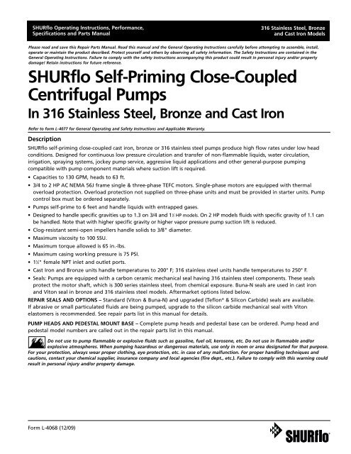
<strong>SHURflo</strong> <strong>Self</strong>-<strong>Priming</strong> <strong>Close</strong>-<strong>Coupled</strong><br />
<strong>Centrifugal</strong> <strong>Pumps</strong><br />
In <strong>316</strong> Stainless Steel, Bronze and Cast Iron<br />
Refer to form L-4077 for General Operating and Safety Instructions and Applicable Warranty.<br />
Description<br />
<strong>SHURflo</strong> self-priming close-coupled cast iron, bronze or <strong>316</strong> stainless steel pumps produce high flow rates under low head<br />
conditions. Designed for continuous low pressure circulation and transfer of non-flammable liquids, water circulation,<br />
irrigation, spraying systems, jockey pump service, aggressive liquid applications and other general-purpose pumping<br />
compatible with pump component materials where suction lift is required.<br />
• Capacities to 130 GPM, heads to 63 ft.<br />
• 3/4 to 2 HP AC NEMA 56J frame single & three-phase TEFC motors. Single-phase motors are equipped with thermal<br />
overload protection. Overload protection not supplied on three-phase units and must be provided in starter units. Pump<br />
control box must be ordered separately.<br />
• <strong>Pumps</strong> self-prime to 6 feet and handle liquids with entrapped gases.<br />
• Designed to handle specific gravities up to 1.3 on 3/4 and 1 1 ⁄2 HP models. On 2 HP models fluids with specific gravity of 1.1 can<br />
be handled. Note that with higher specific gravity or higher vapor pressure pump suction lift is reduced.<br />
• Clog-resistant semi-open impellers handle solids to 3/8" diameter.<br />
• Maximum viscosity to 100 SSU.<br />
• Maximum torque allowed is 65 in.-lbs.<br />
• Maximum casing working pressure is 75 PSI.<br />
•1 1 ⁄2" female NPT inlet and outlet ports.<br />
• Cast Iron and Bronze units handle temperatures to 200° F; <strong>316</strong> stainless steel units handle temperatures to 250° F.<br />
• Seals: <strong>Pumps</strong> are equipped with a carbon ceramic mechanical seal having <strong>316</strong> stainless steel components. These seals<br />
protect the motor shaft, which is 300 series stainless steel, from chemical exposure. Buna-N seals are used in cast iron<br />
and Viton seal in bronze and <strong>316</strong> stainless steel models. Aftermarket options listed below.<br />
REPAIR SEALS AND OPTIONS – Standard (Viton & Buna-N) and upgraded (Teflon ® & Silicon Carbide) seals are available.<br />
If abrasive or small particulated fluids are being pumped, upgrade to the silicon carbide mechanical seal with Viton<br />
elastomers is recommended. See repair parts list in this manual for details.<br />
PUMP HEADS AND PEDESTAL MOUNT BASE – Complete pump heads and pedestal base can be ordered. Pump head and<br />
pedestal model numbers are called out in the repair parts list in this manual.<br />
Do not use to pump flammable or explosive fluids such as gasoline, fuel oil, kerosene, etc. Do not use in flammable and/or<br />
explosive atmospheres. When pumping hazardous or dangerous materials, use only in room or area designated for that purpose.<br />
For your protection, always wear proper clothing, eye protection, etc. in case of any malfunction. For proper handling techniques and<br />
cautions, contact your chemical supplier, insurance company and local agencies (fire dept., etc.). Failure to comply with this warning could<br />
result in personal injury and/or property damage.<br />
Form L-4068 (12/09)
<strong>SHURflo</strong> Operating Instructions, Performance,<br />
Specifications and Parts Manual<br />
<strong>316</strong> Stainless Steel, Bronze<br />
and Cast Iron Models<br />
<strong>SHURflo</strong> <strong>Self</strong>-<strong>Priming</strong> <strong>Close</strong>-<strong>Coupled</strong> <strong>Centrifugal</strong> <strong>Pumps</strong><br />
<strong>316</strong> Stainless Steel, Bronze and Cast Iron Models<br />
Model Ordering Codes and Options<br />
P: Pedestal<br />
Mount<br />
Pump Head Kit<br />
M: Motor (with base)<br />
Example Model: CSMSV62 (1/2 HP ODP motor with >1.15 Service Factor*)<br />
or<br />
CSMSV63T (3/4 HP TEFC motor with 1.0 Service Factor*)<br />
(1) (2) (3) (4) (5) (6) (7)<br />
CS M S V 6 3 T<br />
1st 2nd 3rd 4th 5th 6th 7th<br />
Seal** Impeller Sz. Motor-Mounted Only<br />
Series Mounting Material<br />
(Mech) (NPT Ports) HP AC Type<br />
CS: <strong>Centrifugal</strong><br />
<strong>Self</strong> Prime<br />
and Semiopen<br />
Impeller<br />
M: Motor<br />
(with cast<br />
pump frame<br />
base mount)<br />
P: Pedestal<br />
S: <strong>316</strong> SS Body<br />
and Impeller<br />
B: Bronze Body<br />
and <strong>316</strong> SS<br />
Impeller<br />
C: Cast Iron Body<br />
and Impeller<br />
B: Buna-N<br />
(Stainless Steel Case)<br />
C: Viton<br />
(Stainless Steel Case)<br />
(Silicon Carbide Seal<br />
and Seat Faces)<br />
V: Viton<br />
(Stainless Steel<br />
Case)<br />
T: Teflon<br />
(Stainless Steel<br />
Case)<br />
6 (1 1 ⁄2"- 1 1 ⁄2")<br />
7 (1 1 ⁄2"- 1 1 ⁄2")<br />
8 (1 1 ⁄2"- 1 1 ⁄2")<br />
To identify<br />
your impeller<br />
size, see chart<br />
in owner’s<br />
manual.<br />
1: 1⁄3<br />
2: 1⁄2<br />
3: 3⁄4<br />
4: 1<br />
5: 1 1 ⁄2<br />
6: 2<br />
7: 3<br />
X: 56J<br />
Frame<br />
Motor<br />
”wetend<br />
kit”<br />
Example:<br />
CSMSV6X<br />
Blank: no code<br />
single phase<br />
ODP motor<br />
3: 3 phase ODP<br />
motor<br />
T: 1 phase TEFC<br />
3T: 3 phase TEFC<br />
NOTE: Not all order code combinations (configurations) are standard models available from the manufacturer. Custom model<br />
configurations may require ordering standard components and/or optional parts that will need to be assembled by the customer.<br />
Manufacturer reserves the right to change model order codes, standard models, specifications, and performance without notification.<br />
(*) ODP motors have > 1.15 service factors. Due to service factor, it is recommended TEFC motors are oversized by one HP increment.<br />
Pedestal <strong>Pumps</strong> are not supplied with a motor.<br />
(**) Unless otherwise noted, seal faces are carbon on ceramic.<br />
Form L-4068 (12/09)<br />
2
<strong>SHURflo</strong> Operating Instructions, Performance,<br />
Specifications and Parts Manual<br />
<strong>316</strong> Stainless Steel, Bronze and Cast Iron Models<br />
Performance – Standard Models (Water at 70°)<br />
<strong>316</strong> Stainless Model 3450 RPM Pump Driven Speed<br />
Steel Bronze Cast Iron GPM of Water at Total Head in Feet* Max. Max. Spec.<br />
Models Models Models 0 10 20 30 40 50 60 Head* Gravity<br />
CSMSV6X CSMSV6X CSMSV6X 69 61 52 42 24 4 – 52 1.3<br />
CSMSV63T CSMBV63T CSMCB63T 69 61 52 42 24 4 – 52 1.3<br />
CSMSV633T CSMBV633T CSMCB633T 69 61 52 42 24 4 – 52 1.3<br />
CSMSV7X CSMSV7X CSMSV7X 100 91 79 66 48 7 – 52 1.3<br />
CSMSV75T CSMBV75T CSMCB75T 100 91 79 66 48 7 – 52 1.3<br />
CSMSV753T CSMBV753T CSMCB753T 100 91 79 66 48 7 – 52 1.3<br />
CSMSV8X CSMBV8X CSMCB8X 130 123 113 99 82 61 26 63 1.1<br />
CSMSV863T CSMBV863T CSMCB863T 130 123 113 99 82 61 26 63 1.1<br />
(*) Test data is taken with water at 70°F for pumps with 60 Hz motors at 3450 RPM motors (to convert data to PSI, divide feet of head by 2.31).<br />
Pump performance when pump is new. As pump wears, the performance will decrease.<br />
NOTES: Max Viscosity 100 SSU<br />
Max Specific Gravity 1.1-1.3<br />
Max Torque 65 in.-lbs.<br />
Max suction lift to 6 ft.<br />
Manufacturer reserves the right to change performance without notification.<br />
Form L-4068 (12/09)<br />
3
<strong>SHURflo</strong> Operating Instructions, Performance,<br />
Specifications and Parts Manual<br />
<strong>316</strong> Stainless Steel, Bronze<br />
and Cast Iron Models<br />
<strong>SHURflo</strong> <strong>Self</strong>-<strong>Priming</strong> <strong>Close</strong>-<strong>Coupled</strong> <strong>Centrifugal</strong> <strong>Pumps</strong><br />
<strong>316</strong> Stainless Steel, Bronze and Cast Iron Models<br />
Specifications – Standard Models<br />
DRIVER<br />
PUMP CONSTRUCTION (Wet End)<br />
AC Full Service Port Ship<br />
Model Motor NEMA Motor Load Factor Overload Size Wt.<br />
Number HP Type Frame Voltage Amps Amps** Hz Phase Protection RPM Shaft FNPT Housing Impeller Adapter Seals* (lbs.)<br />
<strong>316</strong> Stainless Steel Models<br />
CSMSV6X 3/4 - 56J Pump Heads only - No motor - - - - - NA 1 1 ⁄2 x 1 1 ⁄2 <strong>316</strong> SS <strong>316</strong> SS <strong>316</strong> SS Viton 45<br />
CSMSV63T 3/4 TEFC 56J 115/208-230 9.80/5.40-4.90 10.60/5.30 60 1 Yes 3450 303 SS 1 1 ⁄2 x 1 1 ⁄2 <strong>316</strong> SS <strong>316</strong> SS <strong>316</strong> SS Viton 45<br />
CSMSV633T 3/4 TEFC 56J 208-230/460 2.50-2.30/1.15 2.60/1.30 60 3 No 3450 303 SS 1 1 ⁄2 x 1 1 ⁄2 <strong>316</strong> SS <strong>316</strong> SS <strong>316</strong> SS Viton 40<br />
190/380 2.70/1.35 ** 50 3 No 2830<br />
CSMSV7X 1 1 ⁄2 - 56J Pump Heads only - No motor - - - - - NA 1 1 ⁄2 x 1 1 ⁄2 <strong>316</strong> SS <strong>316</strong> SS <strong>316</strong> SS Viton 55<br />
CSMSV75T 1 1 ⁄2 TEFC 56J 115/208-230 16.60/9.00-8.30 18.94/9.47 60 1 Yes 3450 303 SS 1 1 ⁄2 x 1 1 ⁄2 <strong>316</strong> SS <strong>316</strong> SS <strong>316</strong> SS Viton 55<br />
CSMSV753T 1 1 ⁄2 TEFC 56J 208-230/460 4.63-4.20/2.10 4.70/2.35 60 3 No 3450 303 SS 1 1 ⁄2 x 1 1 ⁄2 <strong>316</strong> SS <strong>316</strong> SS <strong>316</strong> SS Viton 48<br />
190/380 4.90/2.45 ** 50 3 No 2830<br />
CSMSV8X 2 - 56J Pump Heads only - No motor - - - - - NA 1 1 ⁄2 x 1 1 ⁄2 <strong>316</strong> SS <strong>316</strong> SS <strong>316</strong> SS Viton 50<br />
CSMSV863T 2 TEFC 56J 208-230/460 5.92-5.36/2.68 6.00/3.00 60 3 No 3450 303 SS 1 1 ⁄2 x 1 1 ⁄2 <strong>316</strong> SS <strong>316</strong> SS <strong>316</strong> SS Viton 50<br />
190/380 6.30/3.15 ** 50 3 No 2830 303 SS<br />
Bronze Models<br />
CSMBV6X 3/4 - 56J Pump Heads only - No motor - - - - - NA 1 1 ⁄2 x 1 1 ⁄2 BR <strong>316</strong> SS BR Viton 45<br />
CSMBV63T 3/4 TEFC 56J 115/208-230 9.80/5.40-4.90 10.60/5.30 60 1 Yes 3450 303 SS 1 1 ⁄2 x 1 1 ⁄2 BR <strong>316</strong> SS BR Viton 45<br />
CSMBV633T 3/4 TEFC 56J 208-230/460 2.50-2.30/1.15 2.60/1.30 60 3 No 3450 303 SS 1 1 ⁄2 x 1 1 ⁄2 BR <strong>316</strong> SS BR Viton 40<br />
190/380 2.70/1.35 ** 50 3 No 2830<br />
CSMBV7X 1 1 ⁄2 - 56J Pump Heads only - No motor - - - - - NA 1 1 ⁄2 x 1 1 ⁄2 BR <strong>316</strong> SS BR Viton 55<br />
CSMBV75T 1 1 ⁄2 TEFC 56J 115/208-230 16.60/9.00-8.30 18.94/9.47 60 1 Yes 3450 303 SS 1 1 ⁄2 x 1 1 ⁄2 BR <strong>316</strong> SS BR Viton 55<br />
CSMBV753T 1 1 ⁄2 TEFC 56J 208-230/460 4.63-4.20/2.10 4.70/2.35 60 3 No 3450 303 SS 1 1 ⁄2 x 1 1 ⁄2 BR <strong>316</strong> SS BR Viton 48<br />
190/380 4.90/2.45 ** 50 3 No 2830<br />
CSMBV8X 2 - 56J Pump Heads only - No motor - - - - - NA 1 1 ⁄2 x 1 1 ⁄2 BR <strong>316</strong> SS BR Viton 50<br />
CSMBV863T 2 TEFC 56J 208-230/460 5.92-5.36/2.68 6.00/3.00 60 3 No 3450 303 SS 1 1 ⁄2 x 1 1 ⁄2 BR <strong>316</strong> SS BR Viton 50<br />
190/380 6.30/3.15 ** 50 3 No 2830 303 SS<br />
Cast Iron Models<br />
CSMCB6X 3/4 - 56J Pump Heads only - No motor - - - - - NA 1 1 ⁄2 x 1 1 ⁄2 CI CI CI Buna-N 45<br />
CSMCB63T 3/4 TEFC 56J 115/208-230 9.80/5.40-4.90 10.60/5.30 60 1 Yes 3450 303 SS 1 1 ⁄2 x 1 1 ⁄2 CI CI CI Buna-N 45<br />
CSMCB633T 3/4 TEFC 56J 208-230/460 2.50-2.30/1.15 2.60/1.30 60 3 No 3450 303 SS 1 1 ⁄2 x 1 1 ⁄2 CI CI CI Buna-N 40<br />
190/380 2.70/1.35 ** 50 3 No 2830<br />
CSMCB7X 1 1 ⁄2 - 56J Pump Heads only - No motor - - - - - NA 1 1 ⁄2 x 1 1 ⁄2 CI CI CI Buna-N 55<br />
CSMCB75T 1 1 ⁄2 TEFC 56J 115/208-230 16.60/9.00-8.30 18.94/9.47 60 1 Yes 3450 303 SS 1 1 ⁄2 x 1 1 ⁄2 CI CI CI Buna-N 55<br />
CSMCB753T 1 1 ⁄2 TEFC 56J 208-230/460 4.63-4.20/2.10 4.70/2.35 60 3 No 3450 303 SS 1 1 ⁄2 x 1 1 ⁄2 CI CI CI Buna-N 48<br />
190/380 4.90/2.45 ** 50 3 No 2830<br />
CSMCB8X 2 - 56J Pump Heads only - No motor - - - - - NA 1 1 ⁄2 x 1 1 ⁄2 CI CI CI Buna-N 50<br />
CSMCB863T 2 TEFC 56J 208-230/460 5.92-5.36/2.68 6.00/3.00 60 3 No 3450 303 SS 1 1 ⁄2 x 1 1 ⁄2 CI CI CI Buna-N 50<br />
190/380 6.30/3.15 ** 50 3 No 2830 303 SS<br />
SS = Stainless Steel BR = Bronze CI = Cast Iron ODP = Open Drip Proof TEFC = Totally Enclosed Fan Cooled<br />
(*) Shaft Seals also contain <strong>316</strong> stainless steel, ceramic, and carbon components.<br />
(**) At 208 volts or 50 hertz, the Service Factor Amps are the same as the Full Load Amps.<br />
NOTES: Driver data is subject to change without notice, see label on driver for actual specifications.<br />
All motors include a base (the base may be removable, movable or welded). Motors are not supplied with power cords.<br />
Manufacturer reserves the right to change specifications without notification.<br />
Standard motors listed above are not wash-down or explosion-proof (manufacturer does not stock wash-down or explosion-proof motors).<br />
Thermal overload protection is standard on all single-phase motors (overload protector may have automatic or manual reset); three-phase<br />
motors are not provided with thermal overload protection.<br />
Manufacturer does not specify regulatory compliance for UL, UR, CSA or CE; however most models do comply to UL, UR, CSA and CE.<br />
Form L-4068 (12/09)<br />
4
<strong>SHURflo</strong> Operating Instructions, Performance,<br />
Specifications and Parts Manual<br />
<strong>316</strong> Stainless Steel, Bronze and Cast Iron Models<br />
Dimensions (Inches)<br />
Y<br />
W1**<br />
W2**<br />
Discharge<br />
Suction<br />
S<br />
X<br />
OP<br />
D<br />
Figure 1 - Dimensions<br />
H2<br />
CP**<br />
F<br />
LP<br />
L<br />
MP<br />
H1<br />
E<br />
E<br />
Models<br />
<strong>316</strong> SS Bronze Cast Iron Suc.*Dis.* CP** D E F H1 H2 L LP MP OP S W1**W2** X Y<br />
CSMSV64T CSMBV63T CSMCB63T 1.50 1.50 15.13 4.25 2.25 3.00 0.50 0.75 4.31 1.50 4.38 9.50 4.00 2.88 3.50 5.25 3.81<br />
CSMSV75T CSMBV75T CSMCB75T 1.50 1.50 16.63 4.25 2.25 3.00 0.50 0.75 4.31 1.50 4.38 9.50 4.00 2.88 3.50 5.25 3.81<br />
CSMSV633T CSMBV633T CSMCB633T 1.50 1.50 14.50 4.25 2.25 3.00 0.50 0.75 4.31 1.50 4.38 9.50 4.00 2.88 3.50 5.25 3.81<br />
CSMSV753T CSMBV753T CSMCB753T 1.50 1.50 15.63 4.25 2.25 3.00 0.50 0.75 4.31 1.50 4.38 9.50 4.00 2.88 3.50 5.25 3.81<br />
CSMSV863T CSMBV863T CSMCB863T 1.50 1.50 15.63 4.25 2.25 3.00 0.50 0.75 4.31 1.50 4.38 9.50 4.00 2.88 3.50 5.25 3.81<br />
SS = Stainless Steel.<br />
(*) Standard NPT (female) pipe thread.<br />
(**) This dimension may vary due to motor manufacturing specifications.<br />
NOTE: All dimensions have a tolerance of ± 1/8".<br />
Form L-4068 (12/09)<br />
5
<strong>SHURflo</strong> Operating Instructions, Performance,<br />
Specifications and Parts Manual<br />
<strong>316</strong> Stainless Steel, Bronze<br />
and Cast Iron Models<br />
<strong>SHURflo</strong> <strong>Self</strong>-<strong>Priming</strong> <strong>Close</strong>-<strong>Coupled</strong> <strong>Centrifugal</strong> <strong>Pumps</strong><br />
<strong>316</strong> Stainless Steel, Bronze and Cast Iron Models<br />
Maintenance<br />
Make certain that<br />
the power source is<br />
disconnected before attempting to<br />
service or disassemble any components!<br />
If the power disconnect is out-of-sight,<br />
lock it in the open position and tag to<br />
prevent application of power.<br />
MECHANICAL SEAL REPLACEMENT<br />
Refer to Figures 2, 3 and 4.<br />
IMPORTANT: Always replace both the<br />
seal seat and the seal cartridge as an<br />
assembly to ensure proper mating of<br />
components! It is recommended that<br />
the impeller O-ring (Ref. No. 14) also<br />
be replaced when replacing the<br />
pump seal.<br />
1. Unthread cap screws (Ref. No. 7)<br />
and remove housing (Ref. No. 16)<br />
and O-ring (Ref. No. 8).<br />
Care should be<br />
taken to not pinch<br />
or “shave” the o-ring gasket (Ref. No.<br />
8) between the casing housing and<br />
casing housing cover.<br />
2. Unscrew impeller lock nut<br />
(Ref. No. 15) from the motor shaft<br />
(lock nut unscrews CCW looking at<br />
motor shaft).<br />
NOTE: Some motors use an open end<br />
7/16" wrench across flats on the rear<br />
of the motor shaft (remove bearing<br />
cap for access) to prevent shaft from<br />
turning. Other motor shafts have a<br />
screwdriver slot instead of flats.<br />
3. Unscrew impeller (Ref. No. 13)<br />
from motor shaft. Remove the<br />
impeller O-ring (Ref. No. 14) and<br />
clear all sediment from impeller.<br />
Inspect the impeller O-ring, replace<br />
if deeply scarred or worn. Also,<br />
remove shims (Ref. No. 9) DO NOT<br />
LOSE SHIMS.<br />
4. Remove the adapter and casing<br />
housing cover (Ref. No. 3 and 6) by<br />
unthreading four fasteners<br />
(Ref. No. 4 and 5).<br />
5. Press seal cartridge to remove<br />
(Ref. No. 10) from the rear of the<br />
casing housing cover (Ref. No. 6)<br />
using a wooden dowel.<br />
6. Remove seal seat (Ref. No. 11) from<br />
recess of impeller (Ref. No. 13). Use<br />
caution so as not to damage or<br />
remove seal seat pin (Ref. No. 12)<br />
on Teflon seal-equipped units.<br />
7. Clean casing housing cover and<br />
impeller seal recesses and motor<br />
shaft (Ref. No. 13). Make certain all<br />
surfaces are perfectly clean before<br />
installing new seal parts.<br />
Handle seal parts<br />
with extreme<br />
caution and keep them clean. Do not<br />
touch seal faces (either ceramic or<br />
carbon) with your hands. Do not apply<br />
lubricants on seal faces. This could<br />
cause a leak or premature seal failure.<br />
8. Apply a light coat of sealing<br />
compound to new seal cartridge<br />
(See Figure 2) and press it into the<br />
casing housing cover recess (Ref.<br />
No. 6) using the proper size tube<br />
or installation tool (See Figure 3).<br />
DO NOT press on carbon face or<br />
top of metal cup of the seal<br />
cartridge. Install using flange only.<br />
9. Bolt the adapter (Ref. No. 3) and<br />
casing housing cover (Ref. No. 6)<br />
assembly onto motor mounting<br />
face. Fasten with four fasteners.<br />
10. Press new seal seat (Ref. No. 11)<br />
squarely into the impeller recess<br />
(Ref. No. 13). Align slot in the seal<br />
seat with seal seat pin on Teflonequipped<br />
units. Avoid scratching<br />
the ceramic surface. Use the<br />
cardboard washer (usually supplied<br />
with new seal) to place over the<br />
polished ceramic surface and use a<br />
piece of pipe or dowel rod to press<br />
in firmly but gently (See figure 2).<br />
Avoid scratching the ceramic face,<br />
usually white.<br />
Dispose of cardboard washer.<br />
Check again to see that ceramic<br />
surface is free of dirt and all other<br />
foreign particles and that it has not<br />
been scratched or damaged.<br />
NOTE: Use a soft, clean piece of cloth<br />
on seal seat face when installing to<br />
prevent scratching.<br />
Figure 2 - Mechanical Seal Replacement (Teflon seal shown)<br />
Form L-4068 (12/09)<br />
6
<strong>SHURflo</strong> Operating Instructions, Performance,<br />
Specifications and Parts Manual<br />
<strong>316</strong> Stainless Steel, Bronze and Cast Iron Models<br />
11. Replace any shim washers (Ref. No.<br />
9) which may have been removed<br />
in disassembly (see SHIM<br />
ADJUSTMENT).<br />
Screw the impeller (Ref. No. 13)<br />
back in place, tightening until it is<br />
firmly seated.<br />
12. Install the impeller O-ring (Ref. No.<br />
14), and install and tighten impeller<br />
lock nut to 200 to 225 lbs.<br />
(Ref. No. 15).<br />
NOTE: It will be necessary to remove<br />
plug in motor end cap to expose slot.<br />
If removed, be sure to reinstall plug<br />
AFTER pump is completely assembled.<br />
13. Reinstall o-ring seal (Ref. No. 8) on<br />
casing cover rabbet (Ref. No. 6).<br />
Remount pump housing with six<br />
fasteners (Ref. No. 7).<br />
NOTE: A short “run-in” period may be<br />
necessary to provide completely leakproof<br />
seal operation.<br />
NOTE: Always flush pump thoroughly<br />
before use so as not to contaminate<br />
liquid being pumped.<br />
If the impeller is<br />
replaced, the seal<br />
assembly should also be replaced as<br />
the seal is usually damaged in<br />
disassembly. Also replace impeller<br />
washer.<br />
SHIM ADJUSTMENT<br />
When installing a replacement<br />
impeller (Ref. No. 13) or motor (Ref.<br />
No. 1), it may be necessary to adjust<br />
the number of shims (Ref. No. 9) to<br />
ensure proper running clearance<br />
between the impeller and the casing.<br />
Proceed as follows:<br />
NOTE: A proper running clearance is<br />
less than 0.010". (Face of impeller to<br />
mating face of casing housing.)<br />
1. For the impeller replacement, add<br />
one (1) shim (thinnest 0.005") in<br />
addition to the one (1) removed<br />
originally.<br />
2. For motor replacement, add one<br />
(1) shim (0.015") in addition to the<br />
shims removed during disassembly.<br />
The impeller must be firmly<br />
tightened on the shaft. (to 180<br />
in-lbs torque) The jam nut (Acorn<br />
nut Ref. No. 15) must be tightened<br />
to 200-220 in-lbs.<br />
3. Reassemble the pump as described<br />
in Steps 11, 12, and 13.<br />
IMPORTANT: Ensure that the casing is<br />
snugly in place and check the shaft to<br />
make sure it is turning freely. (Use<br />
7/16" wrench or screwdriver to turn<br />
the shaft.) If it turns freely, check to<br />
ensure that the adapter and casing<br />
housing are fitted “metal to metal”<br />
where they meet on the outside. If<br />
they are not “metal to metal”, tighten<br />
the fasteners (Ref. No. 2, 5, and 7) and<br />
recheck the shaft for free turning.<br />
Tighten carefully, turning the shaft<br />
while tightening so that the motor<br />
bearings are not damaged in the<br />
event that too many shims were<br />
installed. If shaft seizes before<br />
fasteners are completely tight,<br />
disassemble the pump and remove<br />
one (1) shim (thinnest 0.005") and<br />
repeat reassembly.<br />
Seal will produce<br />
some minor drag<br />
when spinning motor shaft, but<br />
rubbing anywhere else must be<br />
eliminated! Otherwise, damage to<br />
pump and/or motor may occur.<br />
Figure 3 - Seal Installation Tool<br />
Form L-4068 (12/09)<br />
7
<strong>SHURflo</strong> Operating Instructions, Performance,<br />
Specifications and Parts Manual<br />
To order parts, contact a <strong>SHURflo</strong> Distributor or Order Direct.<br />
Distributors can be found at www.shurfloindustrial.com.<br />
Please provide following information:<br />
-Model number<br />
-Serial number (if any)<br />
-Part description and number as shown in parts list<br />
1<br />
3 4<br />
Pump Head<br />
5<br />
2<br />
6<br />
8<br />
10<br />
13<br />
11 12 (opt.)<br />
9<br />
20<br />
18<br />
19<br />
7<br />
Mech. Seal<br />
Assembly<br />
Figure 4 – Repair Parts Illustration<br />
<strong>316</strong> Stainless Steel, Bronze<br />
and Cast Iron Models<br />
Optional pedestal mount.<br />
16<br />
15<br />
14<br />
17<br />
Form L-4068 (12/09)<br />
8
<strong>SHURflo</strong> Operating Instructions, Performance,<br />
Specifications and Parts Manual<br />
<strong>316</strong> Stainless Steel, Bronze<br />
and Cast Iron Models<br />
Repair Parts List<br />
Ref.<br />
No. Description <strong>316</strong> SS Units Bronze Units Cast Iron Units Qty<br />
1 *** 3/4 HP 1 PH TEFC Motor for CSMSV63T, CSMBV63T, & CSMCB63T 13409H 13409H 13409H 1<br />
1-1/2 HP 1 PH TEFC Motor for CSMSV75T, CSMBV75T, & CSMCB75T 13410H 13410H 13410H<br />
3/4 HP 3PH TEFC Motor for CSMSV633T, CSMBV633T, & CSMCB633T 14017H 14017H 14017H<br />
1-1/2 HP 3 PH TEFC Motor for CSMSV753T, CSMBV753T, & CSMCB753T 14018H 14018H 14018H<br />
2 HP 3 PH TEFC Motor for CSMSV863T, CSMBV863T, & CSMCB863T 19495H 19495H 19495H<br />
2 5/16-18 Serrated Flange Bolt (18-8 Stainless Steel) † 24386 24386 24386 4<br />
3 Motor Adapter 24248 24248 24248 1<br />
4 3/8 Lock Washer (18-8 Stainless Steel) † 2260-0012 2260-0012 2260-0012 4<br />
5 3/8-16 Hex Head Cap Screw, (18-8 Stainless Steel) † 2210-0100 2210-0100 2210-0100 4<br />
6 Casing Cover 24437S 24437B 24437C 1<br />
7 1/4-20 Hex Head Cap Screw, (18-8 Stainless Steel) † 17485 17485 17485 6<br />
8 O-ring Seal (Standard) 18104 18104 24372 1<br />
Buna-N O-ring * 24372 24372 standard<br />
Viton O-ring * standard standard 18104<br />
Teflon Encapsulated Viton O-ring * 24312 24312 24312<br />
9 Impeller Shim Pack 24337 24337 24337 1<br />
10&11 Seal / Seat Assy (Standard) 13263S 13263S 24443S 1<br />
Seal Assembly (Viton / Carbon / Ceramic) * 1 standard standard 13263S<br />
Seal Assembly (Buna-N / Carbon / Ceramic) * 2 24443S 24443S standard<br />
Seal Assembly (Teflon / Carbon / Ceramic, includes item 12) * 3 24435S 24435S 24435S<br />
Seal Assembly (Viton / Silicon Carbide) * 1 24466S 24466S 24466S<br />
12 Seat Anti-Rotation Pin (used only with Teflon seal) 24302 24302 24302<br />
13 Impeller 0.75 HP Models CSMSV63T, CSMBV63T, CSMCB63T, 24438S 24438S 24438C 1<br />
CSMSV633T, CSMBV633T, & CSMCB633T<br />
Impeller 1-1/2 HP Models CSMSV75T, CSMBV75T, CSMCB75T, 24439S 24439S 24439C<br />
CSMSV753T, CSMBV753T, & CSMCB753T<br />
Impeller 2 HP Models CSMSV863T, CSMBV863T, & CSMCB863T 24440S 24440S 24440C<br />
14 Impeller O-ring (standard) 24314 24314 22937 1<br />
O-ring Buna-N * 22937 22937 standard<br />
O-ring Viton * standard standard 24314<br />
O-ring Teflon Encapsulated Viton * 24310 24310 24310<br />
15 Low Crown Acorn Nut (<strong>316</strong> SS on Stainless Steel <strong>Pumps</strong>) 3 24299 2250-0084 2250-0084 1<br />
16 Pump Housing 24249S 24249B 24249C 1<br />
17 Pipe Plug, 1/8 NPT 24308 24389 24390 1<br />
18 Ground Wire 24387 24387 24387 1<br />
19 1/4 External Tooth Lock Washer (18-8 Stainless Steel) † 2260-0023 2260-0023 2260-0023 1<br />
20 1/4-20 Pan Head Screw - Phillips, (18-8 Stainless Steel) † 24388 24388 24388 1<br />
NOTES:<br />
SS = Stainless Steel<br />
(†) Standard Hardware Item, Available Locally<br />
(*) Optional<br />
(1) Seals also contain <strong>316</strong> stainless steel components, and have Viton bellows.<br />
(2) Seals also contain <strong>316</strong> stainless steel components, and have Buna-N bellows.<br />
(3) Seals also contain <strong>316</strong> stainless steel components, and have Teflon wedge.<br />
*** Drive is subject to change without notice, see label on drive for actual specifications in motor description. PH = phase.<br />
Optional Pedestal Bracket<br />
(Can be substituted for any motor when a pulley drive or 24479 24479 24479<br />
long coupled pump is desired, See Figure 5 for dimensional data.)<br />
Complete Pump Heads, large volute with standard seal (no motor)<br />
3/4 HP Pump Head CSMSV6X CSMBV6X CSMCB6X<br />
1-1/2 HP Pump Head CSMSV7X CSMBV7X CSMCB7X<br />
2 HP Pump Head CSMSV8X CSMBV8X CSMCB8X<br />
Form L-4068 (12/09)<br />
9
<strong>SHURflo</strong> Operating Instructions, Performance,<br />
Specifications and Parts Manual<br />
<strong>316</strong> Stainless Steel, Bronze<br />
and Cast Iron Models<br />
<strong>SHURflo</strong> <strong>Self</strong>-<strong>Priming</strong> <strong>Close</strong>-<strong>Coupled</strong> <strong>Centrifugal</strong> <strong>Pumps</strong><br />
<strong>316</strong> Stainless Steel, Bronze and Cast Iron Models<br />
(Optional) Pedestal Pump Mount Part Number 24479<br />
(Replaces 56J frame motor)<br />
(When long coupling or pulley drive is required)<br />
Figure 5<br />
NOTE: Dimensions have a tolerance of ± 1/8".<br />
(Ø) Diameter.<br />
Form L-4068 (12/09)<br />
10
<strong>SHURflo</strong> Operating Instructions, Performance,<br />
Specifications and Parts Manual<br />
<strong>316</strong> Stainless Steel, Bronze and Cast Iron Models<br />
Troubleshooting Chart<br />
Symptom Possible Cause(s) Corrective Action<br />
Pump runs but no fluid 1. Faulty suction piping 1. Replace<br />
2. Pump located too far from fluid source 2. Relocate<br />
3. Gate valve closed 3. Open<br />
4. Clogged strainer 4. Clean or replace<br />
5. Fouled foot valve 5. Clean or replace<br />
6. Discharge height too great 6. Lower the height<br />
7. Suction lift too great 7. Lower pump<br />
Pump will not prime or 1. Air leak in suction line 1. Repair or replace<br />
retain prime after 2. Clogged foot valve or strainer 2. Clean or replace<br />
operating 3. Specific gravity 3. 4 & 5 Reduce height of suction<br />
too high<br />
lift from fluid by reducing height<br />
4. Viscosity of fluid too high of pump from fluid or use a pump<br />
5. Vapor pressure of fluid too high appropriate for the fluid being<br />
pumped<br />
Pump starts and stops 1. Fouled impeller 1. Clean<br />
pumping 2. Faulty mechanical seal 2. Replace<br />
3. Leak in suction line 3. Repair<br />
4. Leak in foot valve 4. Repair or replace<br />
Flow rate is low 1. Incorrect speed 1. Check drive<br />
2. Piping is fouled or damaged 2. Clean or replace<br />
3. Clogged impeller or worn impeller 3. Clean or replace<br />
4. Discharge line restricted or undersized 4. Flush out piping or replace<br />
5. High discharge pressure 5. Check and reduce<br />
Excessive noise while 1. Pump not secured to firm foundation 1. Secure properly<br />
pump in operation 2. Piping not supported to relieve 2. Make necessary adjustments<br />
strain on pump assembly<br />
3. Restricted suction line 3. Clean or correct<br />
4. Cavitation (noise like marbles in pump) 4. a. Reduce speed<br />
b. Increase inlet size<br />
c. Too viscous (thickness of<br />
material being pumped<br />
too large<br />
Liquid drips from point 1. Damaged mechanical seal 1. Replace (See Mechanical Seal<br />
where shaft enters the<br />
Replacement)<br />
pump casing when pump 2. Temperatures over 200°F – on Cast Iron 2. Lower fluid temperature<br />
is full of liquid<br />
and Bronze or 250°F on Steel<br />
1. Check pump rotation to see if it is CCW 1. On three-phase motors switch any two<br />
Pump runs but as viewed from motor face. On three-phase motor wire leads to reverse rotation.<br />
poor performance<br />
motors, rotation must be checked prior to<br />
running pump under load.<br />
Failure to check rotation before pump is run can<br />
result in severe damage to the pump and motor unit.<br />
Form L-4068 (12/09)<br />
11
<strong>SHURflo</strong> Operating Instructions, Performance,<br />
Specifications and Parts Manual<br />
<strong>316</strong> Stainless Steel, Bronze<br />
and Cast Iron Models<br />
<strong>SHURflo</strong> <strong>Self</strong>-<strong>Priming</strong> <strong>Close</strong>-<strong>Coupled</strong> <strong>Centrifugal</strong> <strong>Pumps</strong><br />
<strong>316</strong> Stainless Steel, Bronze and Cast Iron Models<br />
Impeller Identification Chart<br />
-Semi Open-<br />
Form L-4068 (12/09)<br />
Printed in the USA<br />
FLOW TECHNOLOGIES GROUP<br />
5900 Katella Ave. • Cypress, CA 90630<br />
Phone: (800) 854-3218 • (562) 795-5200 • Fax: (562) 795-7554<br />
www.shurfloindustrial.com