FF PCG-417 DUO inst ENG A0906.pdf - F&F
FF PCG-417 DUO inst ENG A0906.pdf - F&F
FF PCG-417 DUO inst ENG A0906.pdf - F&F

Create successful ePaper yourself
Turn your PDF publications into a flip-book with our unique Google optimized e-Paper software.
<strong>PCG</strong>-<strong>417</strong> <strong>DUO</strong><br />
F&F Filipowski sp. j<br />
ul. Konstantynowska 79/81<br />
95-200 Pabianice POLAND<br />
tel/fax 48 42 2270971<br />
e-mail: fif@fif.com.pl<br />
TIME CONTROLLERS<br />
star-delta switch<br />
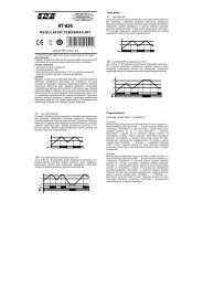
Realisation of time t1 is signaling by pulse shining of red LED.<br />
Take ON a STAR system ( after time t2) is signaliby by shine of red<br />
LED.<br />
DIAGRAM<br />
U<br />
t1<br />
t2<br />
75/150msec<br />
PURPOSE<br />
To control the STAR-DELTAcontactor connection system.<br />
FUNCTIONING<br />
www.fif.com.pl<br />
5 9 0 8 3 1 2 5 9 5 5 0 2 ><br />
F&F products are covered by an 24 months warranty from date of purchase<br />
The <strong>PCG</strong>-<strong>417</strong> relay is equipped with a special system of two<br />
electromagnetic relays which removes the risk of activating two<br />
connectors simultaneously, with each relay controlling a given<br />
connector. Once the system is switched from STAR to DELTA,<br />
one relay disconnects the “star” connector (a forced interval takes<br />
place). The other then activates the “delta” connector.<br />
After the power supply is turned on (green LED is shining), the<br />
joint 7-9 is closed and remains in this position for the preset startup<br />
time t1. After the lapse of t1, joint 7-9 opens and both joints<br />
remain open for the time t2. After the lapse of t2, the joint10-12 is<br />
closed and remains in this position until the power voltage is<br />
disconnected.<br />
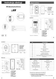
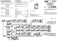
SETTINGS OF ACTIVATION TIME AND DELAY<br />
OF SWITCHING TO<br />
By setting range knob T↔ set choosen time range (for delay<br />
switch for t2=75msec on the left side of scale, but for delay switch<br />
for t2=100msec on the right side of scale ). By knob T×<br />
set value<br />
on the scale from 1 to 10. Product of this values is equal activation<br />
time t1 (e.g.. t1=1s×7=7sec).<br />
U<br />
T↔<br />
75ms 100s<br />
50s<br />
3<br />
2<br />
1<br />
10s<br />
5s<br />
1s<br />
5 6<br />
4<br />
T×<br />
1s<br />
5s<br />
<strong>PCG</strong>-<strong>417</strong><br />
7<br />
8<br />
9<br />
10<br />
150ms<br />
10s<br />
50s<br />
100s<br />
knob of choose<br />
range time<br />
and time switch<br />
time setting<br />
knob<br />
ASSEMBLY<br />
1. Take O<strong>FF</strong> the power.<br />
2. Put on the relay on the rail in the switchgearbox.<br />
3. Cable of power connect with wiring diagram with marks;<br />
voltage 230V to joints 1-3, voltage 24V to joints 1-4.<br />
ATTENTION! : Connect only one of choosen voltages.<br />
4. Power system of coil of connector which switching STAR<br />
system connect in line with joint 7-9.<br />
5. Power system of coil of connector which switching DELTA<br />
system connect in line with joint 10-12.<br />
TECHNICAL DATA<br />
supply<br />
230VAC / 24VAC/DC<br />
current load 2 ×(
75ms 100s<br />
50s<br />
3<br />
2<br />
1<br />
10s<br />
5s<br />
1s<br />
5 6<br />
4<br />
1s<br />
7<br />
8<br />
9<br />
10<br />
150ms<br />
5s<br />
10s<br />
50s<br />
100s<br />
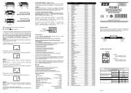
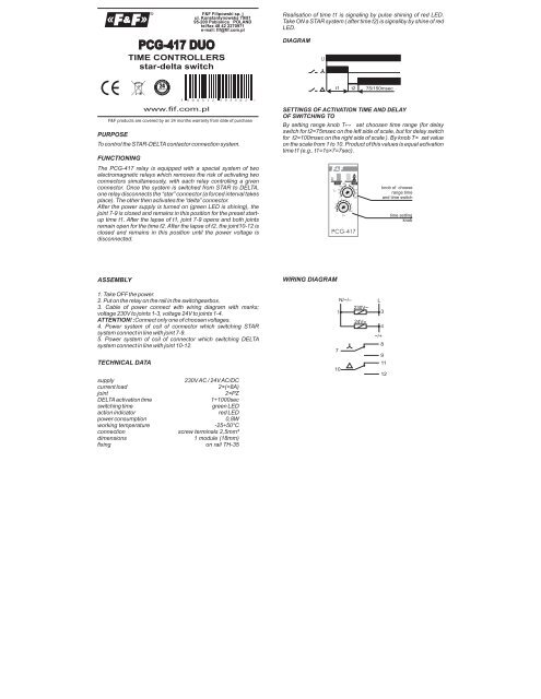
Diagram of switching connector system<br />
STAR - DELTA<br />
N<br />
L1<br />
L2<br />
L3<br />
SG<br />
1<br />
2<br />
3<br />
4<br />
5<br />
6<br />
U V W<br />
U<br />
T↔<br />
T×<br />
S<br />
M3~<br />
X Y Z<br />
<strong>PCG</strong>-<strong>417</strong><br />
7<br />
8<br />
9<br />
10<br />
11<br />
12<br />
S<br />
Y<br />
SG<br />
- main connector<br />
S<br />
- connector of system “DELTA”<br />
S - connector of system “STAR”<br />
A090604