HSM - ATE
HSM - ATE
HSM - ATE

You also want an ePaper? Increase the reach of your titles
YUMPU automatically turns print PDFs into web optimized ePapers that Google loves.
The Leaders in Integrated CAM<br />
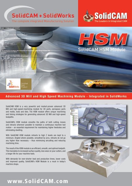
<strong>HSM</strong><br />
SolidCAM <strong>HSM</strong> Module<br />
Advanced 3D Mill and High Speed Machining Module - Integrated in SolidWorks<br />
SolidCAM <strong>HSM</strong> is a very powerful and market-proven advanced 3D<br />
Mill and high-speed-machining module for 3D parts, aerospace parts<br />
and molds, tools and dies. The <strong>HSM</strong> module offers unique machining<br />
and linking strategies for generating advanced 3D Mill and high-speed<br />
toolpaths.<br />
SolidCAM’s <strong>HSM</strong> module smooths the paths of both cutting moves<br />
and retracts wherever possible to maintain a continuous machine tool<br />
motion – an essential requirement for maintaining higher feedrates and<br />
eliminating dwelling.<br />
With SolidCAM <strong>HSM</strong> module retracts to high Z levels are kept to a<br />
minimum. Angled where possible, smoothed by arcs, retracts do not go<br />
any higher than necessary – thus minimizing aircutting and reducing<br />
machining time.<br />
The result of the <strong>HSM</strong> module is an efficient, smooth, and optimal toolpath.<br />
This translates to increased surface quality, less wear on your cutters, and<br />
a longer life for your machine tools.<br />
With demands for ever-shorter lead and production times, lower costs<br />
and improved quality, SolidCAM’s <strong>HSM</strong> Module is a must in today’s<br />
machine shops.<br />
www.SolidCAM.com
The Leaders in Integrated CAM<br />
<strong>HSM</strong> Roughing Strategies<br />
CONTOUR ROUGHING<br />
Contour Roughing is the main strategy<br />
for clearing large volumes of material<br />
effectively. A series of offset passes are<br />
generated at specified Z-depths and<br />
are automatically calculated to remove<br />
the maximum amount of material<br />
without leaving upstands. The depth of<br />
cut automatically adapts, ensuring the<br />
machining of flat faces. Either helix or<br />
profile ramping entry is used. Smoothing<br />
arcs are created automatically, both in<br />
the passes and linking moves, eliminating<br />
dwelling, improving effective cutting<br />
feedrates and tool life.<br />
Hatch roughing<br />
The Hatch Roughing strategy efficiently<br />
removes large material volumes by linear<br />
tool motions, including material removal<br />
at corners. Machining is performed at<br />
automatically defined Z levels that ensure<br />
removing maximum material efficiently.<br />
Machining depth is automatically<br />
calculated to ensure efficient milling at<br />
Horizontal areas between the calculated<br />
Down-steps. This option creates smooth<br />
tool motions thus speeding up milling and<br />
preserving tool life.<br />
REST ROUGHING<br />
Rest Roughing is achieved by following<br />
the work of a big tool with a smaller<br />
tool, in areas not cleared by the previous<br />
operation. The InventorCAM <strong>HSM</strong> module<br />
uses an updated stock model of the<br />
remaining material to avoid air-cutting.<br />
For big parts you can perform more<br />
than one rest roughing operation, with<br />
decreasing tool sizes. Rest Roughing can<br />
also be used when machining castings by<br />
trimming the passes to the cast surface<br />
model, with appropriate stock allowance.<br />
« SolidCAM <strong>HSM</strong> is a powerful solution for all users who need<br />
advanced 3D Mill and high speed machining capabilities... »<br />
<strong>HSM</strong> Finishing Strategies<br />
CONSTANT-Z MACHINING<br />
Helical MACHINING<br />
HORIZONTAL MACHINING<br />
LINEAR MACHINING<br />
Constant-Z machining passes are<br />
generated from a set of surface contours<br />
which describe the shape of surfaces at<br />
different z-heights - like horizontal slices<br />
through the geometry. This is the best<br />
strategy for semi-finishing and finishing<br />
of steep walls. By limiting the Constant-Z<br />
passes to contact angles between 30<br />
to 90 degrees, the steeper areas are<br />
machined, leaving the shallower area for<br />
more appropriate strategies.<br />
Helical machining passes are generated<br />
from a set of surface contours which<br />
describe the shape of surfaces at different<br />
z-heights. The profiles are joined in a<br />
continuous descending ramp that follows<br />
the shape of the model. Helical passes<br />
are generally used for semi-finishing and<br />
finishing.Helical passes are best suited<br />
for surfaces whose angles are between<br />
30 and 90 degrees.<br />
Horizontal Machining strategy<br />
automatically detects all the flat areas<br />
of the part and clears them with an<br />
offsetting path at the z-level of each area,<br />
utilizing similar smoothing charcteristics<br />
as roughing. Linking is also similar to<br />
roughing with helix and profile ramping<br />
entries and smooth linking motions. If the<br />
user requires to machine these flat areas<br />
with more than one pass, any number of<br />
Z-axial offset passes can be added.<br />
Linear Machining is one of the most<br />
widely used finishing strategies. Linear<br />
passes are typically used to semi-finish<br />
cusps from roughing operations and<br />
to finish shallow areas. The passes are<br />
parallel in the XY-plane and follow the<br />
surface in Z-direction. You can choose<br />
their angle as well as their stepover in the<br />
horizontal direction. Cross linear-paths, at<br />
90 degrees to the linear path, are used to<br />
finish the whole part.
SolidCAM <strong>HSM</strong> Module<br />
<strong>HSM</strong><br />
RADIAL machining<br />
Radial machining provides the user<br />
with the ability to machine radial parts.<br />
Machining converges to a central point<br />
with the ability to stop short of the center<br />
of the radial passes, where they become<br />
very dense. This strategy is ideally<br />
suited for use on areas that include<br />
shallow curved surfaces and circular<br />
areas, using contact angles between<br />
0 – 40 degrees.<br />
offset cutting<br />
Offset Cutting calculates the toolpath<br />
based on a defined boundary, defined<br />
distance to either one or both sides of the<br />
boundary and at a constant step over. The<br />
toolpath can be parallel to the boundary<br />
in a to/from manner, or perpendicular to<br />
the boundary. Offset Cutting is used for<br />
machining up to the boundary of a wall<br />
or open cavity.<br />
SPIRAL machining<br />
Spiral machining creates a spiral toolpath<br />
from a given focal point, while keeping<br />
constant contact between the cutter and<br />
workpiece as it machines within a given<br />
boundary. A stepover defines the spacing<br />
between each coil of the pass. The<br />
focal point of the detail to be machined<br />
with spiral or radial passes is located<br />
automatically, or can be determined by<br />
the user.<br />
BOUNDARY MACHINING<br />
A Boundary pass is created by dropping<br />
the cutter onto the surface and running<br />
it along a single boundary or a set of<br />
boundaries to produce the effect of<br />
engraving. It can be applied for engraving<br />
text, chamfering along a profile or<br />
of mold tool runner detail. Negative<br />
machining thickness can be used to<br />
machine at a constant depth below the<br />
surface being machined.<br />
MORPHED machining<br />
Morphed machining controls the toolpath<br />
using flow boundaries and direction<br />
profiles. Morphed passes flow across the<br />
surface in a close-to-parallel formation<br />
with the shape and direction of the passes<br />
dictated by the boundaries around them.<br />
Each path echoes the shape of the one<br />
before and takes on some characteristics<br />
of the one after, thus gradually changing<br />
shape.<br />
3D CONSTANT STEPOVER<br />
3D Constant-stepover finishing strategy<br />
maintains a constant, equidistant<br />
stepover from one toolpath pass to the<br />
next, irrespective of the slope angle of<br />
the part. It creates 3D passes that are<br />
at a constant distance from each other<br />
along the surface of the part, by offsetting<br />
inwards along the surface. This strategy<br />
can be applied within any boundary or to<br />
the whole part.<br />
<strong>HSM</strong><br />
Pencil milling<br />
The Pencil milling strategy creates tool<br />
paths along internal corners and fillets<br />
with small radii, removing material that<br />
no other strategy can reach. The pencil<br />
milling routine is used to finish corners<br />
which might otherwise have cusp marks<br />
left from previous machining operations.<br />
This is ideal for machining into corners<br />
where the surface radius is the same as<br />
the cutter.<br />
Parallel pencil milling<br />
Parallel pencil milling is an extension<br />
to pencil milling where the user can<br />
determine the number and step-over of<br />
multiple-passes, either side of the pencil<br />
tool-path. This is particularly useful when<br />
the previous cutting tool has not been<br />
able to machine all the internal corner<br />
radii to size. These multiple passes will<br />
machine from the outside in to the corner,<br />
creating a good surface finish.<br />
3D CoRNER OFFSET<br />
3D Corner offset machining is similar to<br />
constant stepover machining. However,<br />
rather than start from an outside<br />
boundary and work in towards the center,<br />
a set of pencil passes are created at the<br />
corners of the part. Starting from these<br />
corner passes, a tool path that maintains<br />
an equidistant surface finish is generated<br />
following the 3D form, towards the edges<br />
of the part.<br />
Rest Machining<br />
While pencil milling of vertical corners<br />
can cause both the flute of the cutter<br />
and the radius to be in full contact with<br />
the material, creating adverse cutting<br />
conditions, Rest Machining strategy<br />
picks the corners out from the top<br />
down resulting in better machining<br />
technique. Steep and shallow areas are<br />
both machined in a single toolpath with<br />
different rest machining strategies.
The Leaders in Integrated CAM<br />
<strong>HSM</strong><br />
SolidCAM <strong>HSM</strong><br />
The SolidCAM <strong>HSM</strong> module features several enhancements to CAM technology that make high-speed<br />
operations possible, including: avoiding sharp corners in the tool path, ensuring constant tool-part<br />
contact as much as possible, reducing air-cutting and generating smooth and tangential in/out leads.<br />
Any <strong>HSM</strong> 3D machining strategy can be controlled by specifying the surface slope-angle to be machined<br />
or by specifying the machining boundary. SolidCAM <strong>HSM</strong> module provides a comprehensive set of<br />
boundary creation tools, including Silhouette boundaries, Cutter Contact Area boundaries, Shallow<br />
boundaries, Theoretical Rest Area boundaries, Rest Area boundaries and User-defined boundaries.<br />
SolidCAM <strong>HSM</strong> module is a powerful solution for all users who need advanced 3D Mill and high speed<br />
machining capabilities. It can also be used to improve the productivity of older CNC machines with<br />
reduced air-cutting and smoothing arcs that maintain continuous machine tool motion.<br />
SolidCAM+SolidWorks<br />
Gold-certified SolidWorks Integration and Associativity<br />
With the single-window integration of SolidCAM in SolidWorks, all machining operations can be defined, calculated and<br />
verified without leaving the SolidWorks assembly environment. All 2D and 3D geometries used for machining are fully<br />
associative to the SolidWorks design model. In a single CAM-Part, several SolidWorks Assembly configurations can be<br />
used. Each configuration can represent an independent state or production step of a workpiece.<br />
When the geometry used to define a machining operation is changed in the SolidWorks design, SolidCAM enables the user<br />
to automatically synchronize all machining operations with the updated geometry. The full associativity to the SolidWorks<br />
design model reduces errors when the model changes and facilitates the process where updates are received for models<br />
already machined.<br />
With SolidWorks setting the standard for mainstream CAD systems and SolidCAM’s seamless single-window integration<br />
in SolidWorks - any size organization can reap the benefits of the combined SolidWorks and SolidCAM solution.<br />
About SolidCAM<br />
Founded in 1984, SolidCAM provides manufacturing customers with a full suite of integrated CAM<br />
software modules in SolidWorks for 2.5D Milling, 3D Milling, High Speed Machining, Multi-sided Indexial<br />
4/5 axes Milling, Simultaneous 5-axes Milling, Turning, Mill-Turn up to 5-axes and Wire EDM.<br />
SolidCAM has the Certified Gold Product status from SolidWorks and provides seamless, single-window<br />
integration and full associativity to the SolidWorks design model. The hallmarks of SolidCAM are its ease<br />
of use, combined with its powerful functionality and customized post processors that generate efficient<br />
G-Code.<br />
SolidCAM is used in the mechanical manufacturing, electronics, medical, consumer products, machine<br />
design, automotive and aerospace industries, mold, tool and die and rapid prototyping shops.<br />
SolidCAM has today more than 13,500 seats installed in industry and education. CIMdata, the leading<br />
worldwide strategic consultancy company, has named SolidCAM, in the “Cimdata NC Software Market<br />
Assessment Report”, as the consistent growth leader in CAM over the last five years, with annual growth<br />
rates in the +30% range.<br />
www.SolidCAM.com


![Download [PDF] - SolidCAM](https://img.yumpu.com/41122364/1/190x245/download-pdf-solidcam.jpg?quality=85)

![Download [PDF] - SolidCAM](https://img.yumpu.com/39561632/1/167x260/download-pdf-solidcam.jpg?quality=85)