synchronous machines
synchronous machines
synchronous machines

You also want an ePaper? Increase the reach of your titles
YUMPU automatically turns print PDFs into web optimized ePapers that Google loves.
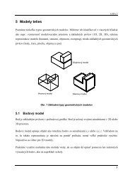
Slovak University of Technology<br />
Faculty of Material Science and Technology in Trnava<br />
ELECTRICAL ENGINEERING<br />
AND ELECTRONICS<br />
Unit 7 - Synchronous Machines and<br />
Direct Current Motors
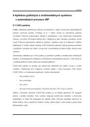
SYNCHRONOUS MACHINES<br />
Round Rotor Machine<br />
• The stator is a ring<br />
shaped laminated ironcore<br />
with slots.<br />
• Three phase windings<br />
are placed in the slots.<br />
• Round solid iron rotor<br />
with slots.<br />
• A single winding is<br />
placed in the slots. Dc<br />
current is supplied<br />
through slip rings.<br />
Concept (two poles)<br />
Rotor with dc<br />
winding<br />
B<br />
A<br />
Stator with<br />
laminated iron-core<br />
C<br />
-<br />
A<br />
-<br />
+ C<br />
N<br />
B<br />
+<br />
B<br />
S<br />
A<br />
-<br />
+<br />
C<br />
Slots with<br />
winding
Synchronous Machines<br />
Salient Rotor Machine<br />
• The stator has a laminated ironcore<br />
with slots and three phase<br />
windings placed in the slots.<br />
• The rotor has salient poles<br />
excited by dc current.<br />
• DC current is supplied to the<br />
rotor through slip-rings and<br />
brushes.<br />
• Concept (two poles)<br />
B - C +<br />
N<br />
A -<br />
A +<br />
S<br />
B +<br />
C -<br />
• The number of poles varies<br />
between 2 - 128.
Synchronous Machines<br />
Round Rotor Generator<br />
Generator<br />
Exciter<br />
View of a two-pole round rotor generator and exciter.
Synchronous Machines<br />
A<br />
Stator with<br />
laminated iron core<br />
C -<br />
Slots with<br />
phase<br />
winding<br />
B<br />
Rotor with<br />
dc winding<br />
A +<br />
+<br />
+<br />
N<br />
B -<br />
C +<br />
-<br />
+<br />
-<br />
-<br />
+<br />
-<br />
+<br />
S<br />
-<br />
AḆ+<br />
C<br />
Major components of a round rotor two-pole generator
SYNCHRONOUS MACHINES<br />
Housing ,cooling ducts<br />
Stator<br />
Rotor<br />
Shaft<br />
Bearing<br />
Stator winding<br />
Rotor winding<br />
Connections
SYNCHRONOUS MACHINES<br />
Construction<br />
• Construction<br />
• The picture shows the laminated<br />
iron core and the slots (empty<br />
and with winding).<br />
• The winding consists of copper<br />
bars insulated with mica and<br />
epoxy resin.<br />
• The conductors are secured by<br />
steel wedges.<br />
• In large <strong>machines</strong>, the stator is<br />
liquid cooled.<br />
• The iron core is supported by a<br />
steel housing.<br />
empty slots<br />
insulated<br />
winding
SYNCHRONOUS MACHINES<br />
Stator<br />
• Laminated iron core<br />
with slots<br />
• Steel Housing
SYNCHRONOUS MACHINES<br />
Iron core<br />
Stator details<br />
• Coils are placed in slots<br />
Coil<br />
• Coil end windings are<br />
bent to form the<br />
armature winding.<br />
Slots<br />
End winding
SYNCHRONOUS MACHINES<br />
Round rotor<br />
• The round rotor is used<br />
for large high speed<br />
(3600rpm) <strong>machines</strong>.<br />
• A forged iron core (not<br />
laminated,DC) is<br />
installed on the shaft.<br />
• Slots are milled in the<br />
iron and insulated<br />
copper bars are placed<br />
in the slots.<br />
• The slots are closed by<br />
wedges and re-enforced<br />
with steel rings.<br />
Round rotor
SYNCHRONOUS MACHINES<br />
Rotor Details
SYNCHRONOUS MACHINES<br />
Round rotor<br />
Shaft<br />
Steel ring<br />
DC current terminals<br />
Wedges
Synchronous Machines<br />
Salient pole generator<br />
Rotor with<br />
dc winding<br />
B +<br />
C -<br />
N<br />
- +<br />
- +<br />
A -<br />
- +<br />
A + - +<br />
- +<br />
S<br />
C +<br />
B -<br />
Stator with<br />
laminated iron core<br />
Slots with<br />
phase<br />
winding<br />
Two-pole salient pole generator concept.
Synchronous Machines<br />
B +<br />
A -<br />
C +<br />
C -<br />
N<br />
- +<br />
- +<br />
A +<br />
S<br />
S<br />
B -<br />
C +<br />
-<br />
- +<br />
+<br />
+<br />
+<br />
N<br />
- +<br />
-<br />
+<br />
-<br />
-<br />
C -<br />
B -<br />
A +<br />
A -<br />
B +<br />
Four-pole salient pole generator concept.
Synchronous Machines<br />
Stator of a large salient pole hydro generator; inset shows the<br />
insulated conductors and spacers.
Synchronous Machines<br />
Large hydro generator rotor with view of the vertical poles.
Synchronous Machines<br />
Slip<br />
rings<br />
Pole<br />
Fan<br />
DC excitation<br />
winding<br />
Rotor of a four-pole salient pole generator.
SYNCHRONOUS MACHINES<br />
Salient pole rotor construction<br />
• The poles are bolted to the shaft.<br />
• Each pole has a DC winding.<br />
• The DC winding is connected to the slip-rings (not shown).<br />
• A DC source supplies the winding with DC through brushes<br />
pressed into the slip ring.<br />
• A fan is installed on the shaft to assure air circulation and<br />
effective cooling.
SYNCHRONOUS MACHINES
SYNCHRONOUS MACHINES<br />
Construction<br />
• Low speed, large hydrogenerators<br />
may have more<br />
than one hundred poles.<br />
• These generators are<br />
frequently mounted vertically.<br />
• The picture shows a large,<br />
horizontally arranged<br />
machine.
DIRECT CURRENT MACHINES<br />
DC machine Construction<br />
Dc motor construction<br />
• The major advantages of DC<br />
<strong>machines</strong> are: easy speed and<br />
torque regulation.<br />
• The stator of the DC motor has<br />
poles, which are excited by DC<br />
current to produce magnetic fields.<br />
• The rotor has a ring-shaped<br />
laminated iron-core with slots.<br />
• Coils with several turns are placed in<br />
the slots. The distance between the<br />
two legs of the coil is about 180<br />
electric degrees.<br />
N<br />
Field<br />
Brush<br />
S<br />
Rotor<br />
Stator with<br />
with poles
DIRECT CURRENT MACHINES<br />
DC machine Construction<br />
Concept of the commutator<br />
• The coils are connected in series.<br />
• The junction points of the coils are<br />
connected to a commutator.<br />
I_<br />
• The commutator consists of<br />
insulated copper segments<br />
mounted in a cylinder.<br />
• Two brushes are pressed to the<br />
commutator to permit current flow.<br />
• The brushes are placed in the<br />
neutral zone (magnetic field is<br />
close to zero) to reduce arcing.<br />
I +<br />
coil<br />
Insulator<br />
Copper
DIRECT CURRENT MACHINES<br />
DC machine Construction<br />
Dc motor stator construction<br />
• The picture shows the stator of a<br />
large DC machine with several<br />
poles.<br />
• Note the interpoles between the<br />
main poles. These poles reduce the<br />
field in the neutral zone and<br />
eliminate arcing of the commutator.<br />
• A compensation winding is placed<br />
on the main poles to increase field<br />
during high load.<br />
• The iron core is supported by a cast<br />
iron frame.<br />
Field poles<br />
Inter pole<br />
Compensation<br />
winding
DIRECT CURRENT MACHINES<br />
DC machine Construction<br />
• The adjoining picture shows the rotor<br />
of a DC machine.<br />
• The rotor iron core is mounted on the<br />
shaft.<br />
• Coils are placed in the slots.<br />
• The end of the coils are bent and<br />
tied together to assure mechanical<br />
strength.<br />
• Note the commutator mounted on<br />
the shaft. It consists of several<br />
copper segments, separated by<br />
insulation.<br />
DC motor rotor construction<br />
Poles<br />
Fan<br />
Brushes<br />
Rotor winding<br />
Bearing<br />
Commutator
DIRECT CURRENT MACHINES<br />
DC Machine Construction<br />
Ring<br />
Insulator<br />
Flag<br />
• The adjoining picture shows the<br />
commutator of a large DC machine.<br />
• The segments are made out of<br />
copper and mica insulation is placed<br />
between the segments.<br />
• The end of each segment has a flag<br />
attached. The coil endings are<br />
welded to these flags.<br />
• An insulated ring is placed on the<br />
coil ends to assure proper<br />
mechanical strength.<br />
Copper
DIRECT CURRENT MACHINES<br />
Operation principles<br />
DC motor operation concept<br />
Stationary<br />
Brushes<br />
• The poles are supplied by DC<br />
current producing a DC magnetic<br />
field.<br />
• The poles are shaped in such a way<br />
the field distribution along the pole is<br />
more or less sinusoidal.<br />
• When the rotor coil is rotated, the<br />
flux linkage changes during the<br />
rotation. It is maximum when the coil<br />
is in vertical position and zero when<br />
it is in horizontal position.<br />
N<br />
S<br />
Rotating Coil Sides
DIRECT CURRENT MACHINES<br />
Concept of commutation<br />
• The current direction changes<br />
as the conductor passes<br />
through the neutral zone.<br />
• The direction of magnetic field<br />
also changes as the conductor<br />
passes through the neutral zone.<br />
Neutral Zone<br />
B<br />
F<br />
B<br />
F<br />
I<br />
N<br />
S<br />
I<br />
N<br />
S<br />
Magnetic field
DIRECT CURRENT MACHINES<br />
Induced voltage and torque calculation.<br />
• The magnetic field is generated by the field current I f .<br />
• The flux Φ f is proportional to the field current.<br />
Φ f = K f I f .<br />
• The K f factor is calculated from the magnetic circuit using Amperes<br />
Law.<br />
• The flux change is proportional to the motor speed ω m .
DIRECT CURRENT MACHINES<br />
Induced voltage and torque calculation.<br />
• The induced voltage after rectification is:<br />
E a = K Φ f ω m = K K f I f ω m = K m I f ω m<br />
• The out put power if the losses are neglected is:<br />
P dc = I a E a = T m ω m .<br />
• The torque is:<br />
T m = I a E a / ω m = K Φ f I a = K m<br />
I f I a
DIRECT CURRENT MACHINES<br />
Equivalent circuit.<br />
• The DC machine can be represented by a voltage source and a<br />
resistance connected in series. The armature winding has a resistance,<br />
R a .<br />
• The field circuit is represented by a winding that generates the magnetic<br />
field and a resistance connected in series. The field winding has<br />
resistance R f .<br />
R a<br />
R f<br />
I f<br />
Φ f<br />
I a<br />
E a<br />
V a<br />
V f
DIRECT CURRENT MACHINES<br />
Equivalent circuit.<br />
The equations are:<br />
Φ f = K f I f<br />
R a<br />
E a = K Φ f w m = K m I f ω m<br />
E a = V a + I a<br />
R a<br />
R f<br />
Φ<br />
f<br />
E a<br />
I a<br />
V a<br />
V f = I f R f<br />
V f<br />
I f<br />
T m = K Φ f I a = K m I f I a
DIRECT CURRENT MACHINES<br />
Type of DC <strong>machines</strong>.<br />
• Separately excited machine.<br />
The main winding supplies the load.<br />
The field winding is supplied by a separate DC source whose voltage is<br />
variable.<br />
Good speed control.<br />
Φ f<br />
V a<br />
V f
DIRECT CURRENT MACHINES<br />
Type of DC <strong>machines</strong>.<br />
• Shunt DC machine.<br />
The armature and field windings are connected in parallel.<br />
Constant speed operation.<br />
Φ f<br />
V a
DIRECT CURRENT MACHINES<br />
Major Types of DC <strong>machines</strong>.<br />
• Series DC machine.<br />
The armature and field winding are connected in series.<br />
High starting torque.<br />
V a<br />
Φ s
DIRECT CURRENT MACHINES<br />
Major Types of DC <strong>machines</strong>.<br />
• Compound DC machine.<br />
The machine has two field windings: One connected in series; the other<br />
in parallel.<br />
The series winding provides additional, load dependent excitation.<br />
Reduced voltage drop at high load.<br />
Φ s<br />
Φ f<br />
V a