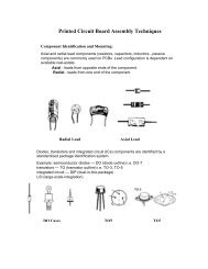
Logic Probe - Technology - Niagara College
Logic Probe - Technology - Niagara College
Logic Probe - Technology - Niagara College

Create successful ePaper yourself
Turn your PDF publications into a flip-book with our unique Google optimized e-Paper software.
A Electronic Trainer<br />
Theory of Operation<br />
Copyright © 2004<br />
D. L. Gould & <strong>Niagara</strong> <strong>College</strong><br />
<strong>Niagara</strong> <strong>College</strong> - <strong>Technology</strong>
System Diagram<br />
Pulse<br />
74LS00<br />
FPTs<br />
Oscillator<br />
SIN/SQR<br />
+ 5V<br />
Clock<br />
LM555<br />
<strong>Logic</strong><br />
<strong>Probe</strong><br />
+12V<br />
-12V<br />
State Leds<br />
CA3086<br />
I/O Machine<br />
Socket<br />
State<br />
Switches
U2<br />
5<br />
U3<br />
Five point term & Din<br />
-12 Volts<br />
BLU<br />
+12 Volts<br />
ORG<br />
Clock<br />
PLS<br />
COM<br />
BLK<br />
X020<br />
X020<br />
+5 Volts<br />
RED<br />
Square wave<br />
Sine wave<br />
X075<br />
Title<br />
Electronic Trainer<br />
<strong>Niagara</strong> <strong>College</strong> <strong>Technology</strong><br />
Course<br />
ELNC 1236<br />
Date<br />
October 28, 2003 Page 2 of 2
Function Generator<br />
<strong>Logic</strong> <strong>Probe</strong><br />
R27<br />
470K<br />
DC Offset<br />
R28<br />
100K<br />
Sine Amplitude<br />
R25<br />
100K<br />
3 2<br />
10<br />
C7<br />
10 uf<br />
FTP 1<br />
S6<br />
Freq. Range<br />
D10<br />
D9<br />
R18<br />
680K<br />
5V<br />
4<br />
U4B<br />
14572<br />
3<br />
2<br />
U4A<br />
1<br />
Low<br />
14572 D6<br />
5V<br />
+12V<br />
-12V<br />
C6<br />
.1 uf<br />
R22<br />
5K1<br />
R23<br />
5K1<br />
R26 270R<br />
R24<br />
10K<br />
4<br />
11<br />
R21<br />
10K<br />
14 12<br />
U5<br />
13 XR2206<br />
R29<br />
100K<br />
7<br />
6<br />
5<br />
Freq. Control<br />
1N4733<br />
C8<br />
.001 uf<br />
C9<br />
.01 uf<br />
FTP 2<br />
C10<br />
.1 uf<br />
C11<br />
1 uf<br />
<strong>Probe</strong><br />
Connection<br />
R16<br />
1M0<br />
R17<br />
1M0<br />
5V<br />
D11<br />
D12<br />
C3<br />
0.01uf<br />
R19<br />
1M0<br />
13<br />
10<br />
7<br />
6<br />
U4D<br />
U4F<br />
14572<br />
14572<br />
9<br />
NOR Gate<br />
U4C 5<br />
14572<br />
14<br />
15<br />
C4<br />
1uf<br />
R20<br />
100K<br />
5V<br />
High<br />
D7<br />
1N4733<br />
12<br />
U4E<br />
11<br />
Pulse<br />
14572<br />
D8<br />
S5<br />
Square<br />
Amplitude<br />
1N5223<br />
1N4148<br />
1N5223<br />
1N4148<br />
Title<br />
Date<br />
<strong>Niagara</strong> <strong>College</strong> <strong>Technology</strong><br />
<strong>Logic</strong> <strong>Probe</strong> & Function Generator for the Electronic Trainer<br />
October 28, 2003 Course ELNC 1236 Page 1 of 2
-12 Volts<br />
BLU<br />
+12 Volts<br />
ORG<br />
Clock<br />
PLS<br />
COM<br />
BLK<br />
X020<br />
X020<br />
+5 Volts<br />
RED<br />
Square wave<br />
Sine wave<br />
X075
Adapter<br />
● The adapter changes the 120 VAC from the wall<br />
outlet, to DC voltages of +5Vdc/1 A (FPT3),<br />
+12Vdc/250 Ma (FPT7), -12Vdc/250 Ma (FPT8). It<br />
will supply voltages to the Electronic Trainer when<br />
attached to the five pin DIN connector.<br />
+ 5V<br />
+12V<br />
-12V
Pulse (74LS00)<br />
● The pulse circuit uses a quad 2-input NAND gate<br />
which will provide a single pulse at FPT5, when<br />
the gate input is toggled with the pulse switch S4.<br />
Pulse<br />
74LS00
Clock (555)<br />
● The clock circuit uses a LM555 timer IC which<br />
will provide a pulse, 1 Hz to 7 Hz at FPT6 when<br />
R8, a 500K potentiometer is adjusted minimum<br />
to maximum.<br />
Clock<br />
LM555
FPTs (Tie Points)<br />
● There are eight (FPT1 to FPT8) tie points on the<br />
Electronic Trainer that allow access to power<br />
sources, clock, pulse and the oscillator output.<br />
FPTs
<strong>Logic</strong> <strong>Probe</strong><br />
● <strong>Logic</strong> <strong>Probe</strong><br />
● displays logic levels (high, low, pulse) on LEDs<br />
<strong>Logic</strong> <strong>Probe</strong> LED States<br />
High Low Pulse<br />
Input<br />
Signal<br />
Condition<br />
<strong>Logic</strong> “0” no pulse activity<br />
<strong>Logic</strong> “1” no pulse activity<br />
All LEDs off<br />
1. Test point is an open circuit<br />
2. Out of tolerance signal<br />
3. No power to probe circuit<br />
4. Node or circuit not powered<br />
Equal brightness of the Hi and<br />
Low LEDs indicates<br />
approximately a 50% duty cycle<br />
square wave<br />
<strong>Logic</strong> <strong>Probe</strong><br />
MC14572UB
SIN/SQR Oscillator<br />
● Based on the popular XR2206 function<br />
generator integrated circuit, capable of<br />
producing sine and square waveforms.<br />
• S6/R29 - 1 Hz to100KHz Freq. Range<br />
• R28 - Sine Amplitude Control FPT1<br />
• S5 - Square Amplitude Control FPT2<br />
Oscillator<br />
SIN/SQR
State LEDs (3086)<br />
● LEDs - light-emitting diodes that glow when a<br />
proper polarity and voltage are applied to them. A<br />
digital 1(on) indicates a high state, and a digital<br />
0(off) indicates a low state.<br />
● The CA3086 is a transistor array which acts as a<br />
switch to enable the LEDs when base current is<br />
applied to the transistor, causing current to flow<br />
between the collector & emitter<br />
State Leds<br />
CA3086
I/O Machine Socket<br />
● Solid wire jumpers inserted into this socket,<br />
provide access to the “state switches” and<br />
“state LEDs”, of the Electronic Trainer.<br />
I/O Machine<br />
Socket
State Switches<br />
● Each of the four switches is connected to<br />
the 5Vdc positive. Toggling the switch(es)<br />
closed will provide a positive voltage at the<br />
respective position(s) on the I/O machine<br />
socket.<br />
State<br />
Switches
Breadboard<br />
● The breadboard attached to the cabinet will<br />
allow the user to construct and explore<br />
various digital and linear experiments using<br />
the circuitry of the Electronic Trainer.
Summary<br />
● Flexibility - +5Vdc/1 A, +12Vdc/250 mA, -<br />
12Vdc/250 mA adapter.<br />
● Pulse & clock availability<br />
● Sine / Square Oscillator<br />
● <strong>Logic</strong> <strong>Probe</strong> - high/low/pulse<br />
● Breadboard for digital/linear experiments
Where to get more<br />
information<br />
● Data sheets on LM555, CA3086, DM74LS00, XR2206<br />
and the MC14572UB<br />
● Schematics of the Electronic Trainer<br />
● Digital Systems 7th Edition Text - Tocci