2455SK.pdf (6.35 MB) - Bayliner Parts
2455SK.pdf (6.35 MB) - Bayliner Parts
2455SK.pdf (6.35 MB) - Bayliner Parts

You also want an ePaper? Increase the reach of your titles
YUMPU automatically turns print PDFs into web optimized ePapers that Google loves.
Engine Serial Number:<br />
Hull Identification Number:<br />
Hull Identification Number<br />
The Hull Identification Number (HIN) is located on the starboard side of the transom. Be sure to record the HIN (and<br />
the engine serial numbers) in the space provided above. Please refer to the HIN for any correspondence or orders.<br />
HIN LOCATION<br />
© 2000 <strong>Bayliner</strong> Technical Publications. All rights reserved.<br />
No part of this publication may be reproduced, stored in any retrieval system, or transmitted in any form by any means,<br />
electronic, mechanical, photocopying, recording or otherwise, without prior written permission of <strong>Bayliner</strong>.<br />
Printed in the United States of America.<br />
General Notes<br />
The material in this document is for information only and is subject to change without notice. While reasonable efforts have<br />
been made in the preparation of this document to assure its accuracy, <strong>Bayliner</strong> assumes no liability resulting from errors or<br />
omissions in this document, or from the use of information contained herein.<br />
Due to our commitment to product improvement, <strong>Bayliner</strong> reserves the right to make changes in the product design,<br />
specifications, and equipment at any time without notice or obligation. Illustrations and/or photos may show optional equipment.<br />
All <strong>Bayliner</strong> products meet or exceed USCG (Unites States Coast Guard) and/or NMMA (National Marine Manufacturer’s<br />
Association) construction standards. Manufactured with 1,1,1 Trichloroethane, a substance which harms public health and<br />
environment during the manufacturing process by destroying ozone in the upper atmosphere.<br />
Proprietary Rights<br />
This document discloses subject matter in which <strong>Bayliner</strong> has proprietary rights. The information and design disclosed herein<br />
were originated by and are the property of <strong>Bayliner</strong>. Neither receipt nor possession thereof confers or transfers any right to<br />
reproduce, copy, alter or disclose the document or any part thereof, any information contained therein, or to construct boats or<br />
any item from it, except by written permission from or written agreement with <strong>Bayliner</strong>. This document is to be returned upon<br />
request to <strong>Bayliner</strong>.
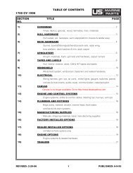
CONTENTS<br />
Chapter 1: Welcome Aboard!<br />
1 Dealer Service<br />
1 Boating Experience<br />
1 Engine/Accessories Guidelines<br />
1 Qualified Maintenance<br />
2 Special Care For Moored Boats<br />
2 Safety Standards<br />
3 Hazard Boxes & Symbols<br />
Chapter 2: Features & Systems<br />
4 Dimensions and Tank Capacities<br />
4 Layout View<br />
5 Hull Exterior Hardware & Drains<br />
6 Deck Hardware<br />
8 Windshield Wiper<br />
8 Electrical System<br />
9 12 Volt DC System<br />
9 Fuses and Circuit Breakers<br />
9 Batteries<br />
9 Battery Switch<br />
10 Battery Charger (LX models only)<br />
12 Audio Equipment<br />
12 Navigation & Communication Equipment<br />
12 VHF Radio (LX models only)<br />
12 Compass (LX models only)<br />
12 Depth Finder (LX models only)<br />
13 Lighting<br />
13 Navigation and Interior Lights<br />
13 Appliances<br />
14 Propulsion<br />
14 Engine<br />
14 Fuel System<br />
14 Fuel Fill and Vent<br />
14 Fuel Filters<br />
14 Anti-siphon Valve<br />
15 Bilge Blower<br />
15 Trim Tabs<br />
16 Bilge Pumps<br />
17 Autofloat Switches<br />
17 Freshwater System (LX models only)<br />
18 Water Heater (LX Models Only)<br />
19 Raw Water System<br />
19 Seacocks<br />
19 Raw Water Strainers<br />
20 Marine Head with Holding Tank<br />
(LX Models Only)<br />
20 Gray Water Drain System<br />
21 Air Conditioning System (Option)<br />
22 Warning Label Locations<br />
23 Canvas Top Installation<br />
Chapter 3: Electrical Routings<br />
Chapter 4: Wiring Schematics<br />
27 Single Dockside<br />
28 Dual Dockside<br />
29 Engine Electrical System<br />
Limited Warranty<br />
30 What Is Not Covered<br />
30 Other Limitations<br />
30 Your Obligation
Chapter 1: Welcome Aboard! 1<br />
Chapter 1: Welcome Aboard!<br />
This owner’s manual supplement provides specific information about your boat that is not covered in the owner’s<br />
manual. Please study the owner’s manual and this supplement carefully, paying particular attention to the Limited<br />
Warranty in this supplement. Keep the owner’s manual and supplement on your boat in a secure, yet readily available<br />
place.<br />
Dealer Service<br />
Make sure you receive a full explanation of all systems from the selling dealer before taking delivery of your boat.<br />
Your selling dealer is your key to service. If you experience any problems with your new boat, immediately contact<br />
the selling dealer. If for any reason your selling dealer is unable to help, you can call us direct on our customer service<br />
hotline: 360-435-8957 or send us a FAX: 360-403-4235.<br />
Boating Experience<br />
If this is your first boat or if you are changing to a type of boat you are not familiar with, for your own comfort and<br />
safety, please ensure that you obtain handling and operating experience before assuming command of the boat.<br />
We strongly recommend that you take one of the boating safety classes offered by the U.S. Power Squadrons or the<br />
U.S. Coast Guard Auxiliary. For more course information, including dates and locations of upcoming classes, contact<br />
the organizations directly:<br />
• U.S. Power Squadrons: 1-888-FOR-USPS (1-888-367-8777) or on the Internet at: http://www.usps.org<br />
• U.S. Coast Guard Auxiliary: 1-800-368-5647 or on the Internet at: http://www.cgaux.org<br />
Outside the United States, your selling dealer, national sailing federation or local boat club can advise you of local<br />
sea schools or competent instructors.<br />
! WARNING!<br />
CONTROL HAZARD! A qualified operator must be in control of the boat at all times. DO NOT<br />
operate your boat while under the influence of alcohol or drugs.<br />
Engine/Accessories Guidelines<br />
Your boat’s engine and accessories were selected to provide optimum performance and service. Installing a different<br />
engine or other accessories may cause unwanted handling characteristics. Should you choose to install a different<br />
engine or to add accessories that will affect the boat’s running trim, have an experienced marine technician perform a<br />
safety inspection and handling test before operating your boat again.<br />
Please be advised that certain modifications to your boat can result in cancellation of your warranty<br />
protection. Always check with your dealer before making any modifications to your boat.<br />
The engine and accessories installed on your boat come with their own operation and maintenance manuals. We<br />
strongly urge you to read and understand these manuals before operating the engine and accessories.<br />
Qualified Maintenance<br />
Failure to maintain your boat’s systems as designed could violate the laws in your jurisdiction and could expose you<br />
and other people to the danger of bodily injury or accidental death. We recommend that you follow the instructions<br />
provided in the owner’s manual this owner's manual supplement, the engine owner’s manual and all accessory<br />
instruction sheets/manuals included in your boat’s owner’s packet.<br />
! WARNING!<br />
To maintain the integrity and safety of your boat, only qualified personnel should perform<br />
maintenance on, or in any way modify: The steering system, propulsion system, engine control<br />
system, fuel system, environmental control system, electrical system or navigational system.<br />
Ciera 2455 Cruiser • Owner’s Manual Supplement
2 Chapter 1: Welcome Aboard!<br />
Special Care For Moored Boats<br />
If moored in saltwater or fresh water, your boat will collect marine growth on its hull bottom. This will detract from<br />
the boat’s beauty, greatly affect its performance and may damage the gelcoat. There are two methods of slowing<br />
marine growth:<br />
• Periodically haul the boat out of the water and scrub the hull bottom with a bristle brush and a solution of soap and<br />
water.<br />
NOTICE<br />
• To help seal the hull bottom and reduce the possibility of gelcoat blistering on moored boats,<br />
we recommend the application of an epoxy barrier coating, such as INTERLUX, Interprotect<br />
2000E/2001E. The barrier coating should be covered with several coats of anti-fouling paint.<br />
• Many states regulate the chemical content of bottom paints in order to meet environmental<br />
standards. Check with your local dealer about recommended bottom paints, and about the<br />
laws in effect in your area.<br />
Safety Standards<br />
Your boat’s mechanical and electrical systems were designed to meet safety standards in effect at the time it was<br />
built. Some of these standards were mandated by law, all of them were designed to insure your safety, and the safety<br />
of other people, vessels and property.<br />
In addition to this owner’s manual supplement, please read the owner’s manual and all accessory instruction<br />
sheets for important safety standards and hazard information.<br />
!<br />
DANGER!<br />
PERSONAL SAFETY HAZARD! Do not allow anyone to ride on parts of the boat<br />
not designated for such use. Sitting on seat backs, lounging on the forward deck,<br />
bow riding, gunwale riding or occupying the transom platform while underway is<br />
especially hazardous and will cause personal injury or death.<br />
Ciera 2455 Cruiser • Owner’s Manual Supplement
Hazard Boxes & Symbols<br />
Chapter 1: Welcome Aboard! 3<br />
The hazard boxes and symbols shown below are used throughout this supplement to call attention to potentially<br />
dangerous situations which could lead to either personal injury or product damage. We urge you to read these<br />
warnings carefully and follow all safety recommendations.<br />
!<br />
DANGER!<br />
This box alerts you to immediate hazards which WILL cause severe personal injury or death if<br />
the warning is ignored.<br />
! WARNING!<br />
This box alerts you to hazards or unsafe practices which COULD result in severe personal<br />
injury or death if the warning is ignored.<br />
! CAUTION!<br />
This box alerts you to hazards or unsafe practices which COULD result in minor personal<br />
injury or cause product or property damage if the warning is ignored.<br />
NOTICE<br />
This box calls attention to installation, operation or maintenance information, which is important<br />
to proper operation but is not hazard related.<br />
EXPLOSION<br />
HAZARD!<br />
OPEN FLAME<br />
HAZARD!<br />
HOT<br />
HAZARD!<br />
ELECTRICAL<br />
HAZARD!<br />
PERSONAL INJURY<br />
& FALLING HAZARD!<br />
ROTATING<br />
PROPELLER HAZARD!<br />
Ciera 2455 Cruiser • Owner’s Manual Supplement
4 Chapter 2: Features & Systems<br />
Chapter 2: Features & Systems<br />
Dimensions and Tank Capacities<br />
Overall<br />
Length<br />
Bridge<br />
Clearance<br />
Beam<br />
Draft<br />
(Drive Up)<br />
Fuel Capacity<br />
(gal)<br />
Freshwater<br />
Capacity (gal)<br />
Waste holding Tank<br />
Capacity (gal)<br />
24’0” 6’ 9” 8’ 5” 1’5” 65 20 20 (LX models only)<br />
Layout View<br />
fender<br />
stowage<br />
stowage<br />
beneath<br />
folding<br />
transom<br />
seat<br />
stowage 48 qt<br />
cooler beneath<br />
fold down<br />
SunChaiser<br />
lounge<br />
mid ship<br />
cleats<br />
TM<br />
anchor station<br />
w/ hawse pipe<br />
transom<br />
door<br />
stowage<br />
helm<br />
bench<br />
seat<br />
mid ship<br />
cleats<br />
stowage<br />
open<br />
hanging<br />
locker<br />
sink<br />
stove<br />
trash bin<br />
ice chest<br />
dinette<br />
converts<br />
to v-berth<br />
portapotti<br />
open<br />
hanging<br />
locker<br />
sink<br />
Ciera 2455 Cruiser • Owner’s Manual Supplement
Chapter 2: Features & Systems 5<br />
Hull Exterior Hardware & Drains<br />
FUEL TANK, FRESH WATER<br />
TANK & HOLDING TANK VENTS<br />
AIR COND.<br />
DRAIN<br />
AIR COND.<br />
OVERBOARD<br />
STARBOARD HULLSIDE<br />
BOW<br />
EYE<br />
AFT BILGE<br />
PUMP DRAIN<br />
COCKPIT<br />
DRAINS<br />
STORAGE<br />
DRAIN<br />
FWD. BILGE<br />
PUMP DRAIN<br />
SHOWER<br />
SUMP DRAIN<br />
HEAD SINK<br />
DRAIN<br />
PORT HULLSIDE<br />
ROPE LOCKER DRAIN<br />
GALLEY DRAIN<br />
COCKPIT DRAINS<br />
TRANSOM<br />
VIEW<br />
TRIM TAB (TYPICAL) STERN EYE<br />
GARBOARD DRAIN MACERATOR OVERBOARD SWIM STEP LADDER<br />
DISCHARGE (OPTION)<br />
Ciera 2455 Cruiser • Owner’s Manual Supplement
6 Chapter 2: Features & Systems<br />
Deck Hardware<br />
VENTILATION LOUVERS<br />
FOR ENGINE<br />
COMPARTMENT<br />
FUEL TANK<br />
FILL FITTING<br />
WATER TANK<br />
FILL FITTING<br />
WASTE PUMP-OUT<br />
FITTING<br />
PUMP OUT LOCATIONS<br />
BOW CLEAT<br />
ROPE CHOCK<br />
(TYPICAL)<br />
ANCHOR ROLLER<br />
VIEW OF FOREDECK<br />
HAWSE PIPE<br />
SIDELIGHTS<br />
(TYPICAL)<br />
Ciera 2455 Cruiser • Owner’s Manual Supplement
Chapter 2: Features & Systems 7<br />
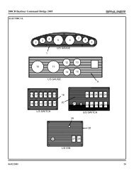
Cockpit Layout<br />
VOLTMETER TEMPERATURE OIL PRESSURE<br />
GAUGE GAUGE<br />
GAUGE<br />
TACHOMETER<br />
SPEEDOMETER<br />
COMPASS<br />
12 VOLT<br />
ADAPTER<br />
FUEL<br />
GAUGE<br />
TRIM TAB<br />
GAUGE<br />
COCKPIT<br />
LIGHTS<br />
ANCHOR<br />
LIGHTS<br />
DEPTH FINDER<br />
(LX MODELS)<br />
FWD & AFT<br />
BILGE PUMP<br />
SWITCHES<br />
TRIM TAB<br />
SWITCHES<br />
HORN<br />
SWITCH<br />
BLOWER<br />
SWITCH<br />
WIPER SWITCH<br />
ACCESSORY<br />
SWITCHES<br />
IGNITION<br />
ACCESSORY CIRCUIT<br />
BREAKER PANEL<br />
VHF RADIO<br />
(LX MODELS)<br />
NAVIGATION<br />
LIGHTS<br />
VHF RADIO<br />
(LX MODELS)<br />
SHIFT/THROTTLE<br />
LEVER<br />
Ciera 2455 Cruiser • Owner’s Manual Supplement
8 Chapter 2: Features & Systems<br />
Windshield Wiper<br />
• The windshield wiper control switch is located at the helm.<br />
• Periodically, the wiper blade will need to be replaced using 18” blade refills.<br />
• To improve visibility; keep your windshield clean and regularly apply a good quality anti-rain solution to the<br />
exterior panes and an anti-fog solution to the interior panes.<br />
Electrical System<br />
We strongly recommend that you read and understand this section and the electrical section of the owner’s manual.<br />
Electrical routing drawings are provided in Chapter 3 of this supplement; wiring schematics in Chapter 4.<br />
!<br />
DANGER!<br />
EXTREME FIRE, SHOCK & EXPLOSION HAZARD!<br />
• To minimize the risks of fire and explosion, NEVER install knife switches or other arcing<br />
devices in the fuel compartments.<br />
• NEVER substitute automotive parts for marine parts. Electrical, ignition and fuel system<br />
parts were designed and manufactured to comply with rules and regulations that minimize<br />
risks of fire and explosion.<br />
• DO NOT modify the electrical systems or relevant drawings.<br />
• Only qualified personnel should install batteries and/or perform electrical system<br />
maintenance.<br />
• Insure that all battery switches are turned OFF before performing any work in the engine<br />
spaces.<br />
!<br />
WARNING!<br />
FIRE, OPEN FLAME & EXPLOSION HAZARD!<br />
• Fuel fumes are heavier than air and will collect in the bilge areas where they can be accidently<br />
ignited. Visually and by smell (sniff test), check the engine and fuel compartments for<br />
fumes or accumulation of fuel. ALWAYS operate the bilge blowers for at least four minutes<br />
prior to engine starting, electrical system maintenance or activation of electrical devices.<br />
• Minimize the danger of fire and explosion by not exposing batteries to open flame or sparks.<br />
It is also important that no one smoke anywhere near the batteries.<br />
! CAUTION!<br />
SHOCK & ELECTRICAL SYSTEM DAMAGE HAZARD! NEVER disconnect the<br />
battery cables while the engine is running since it can cause damage to your boat’s<br />
electrical system components.<br />
NOTICE<br />
Electrical connections are prone to corrosion. To reduce corrosion caused electrical problems,<br />
keep all electrical connections clean and apply a spray-on protectant that is designed to protect<br />
connections from corrosion.<br />
Ciera 2455 Cruiser • Owner’s Manual Supplement
12 Volt DC System<br />
Fuses and Circuit Breakers<br />
The engine is protected by a large circuit<br />
breaker located on the engine. The accessories<br />
are protected by circuit breakers on the<br />
battery switch panel and by the accessory<br />
circuit breakers located below the steering<br />
wheel. Wires are color-coded to indicate<br />
which accessory each fuse services. Some<br />
items, such as radios and bilge pumps, may<br />
be fused individually at the unit. Autofloat<br />
switches are fused at the battery.<br />
VOLTMETER<br />
Chapter 2: Features & Systems 9<br />
ENGINE<br />
COMPARTMENT<br />
BATTERIES<br />
AFT<br />
STBD.<br />
Batteries<br />
The batteries supply electricity for lights,<br />
accessories and engine starting.<br />
The Electrical section of Chapter 7, in the<br />
Owner’s Manual, provides battery, care and<br />
maintenance instructions.<br />
Battery Switch<br />
The battery switch (located in the cockpit<br />
under the port lounge seat) has four (4)<br />
positions (see lower photograph on right);<br />
• Position "1" - Provides power, for engine<br />
starting and accessories, from battery<br />
"1". Battery "1" (only) will be charged by<br />
the engine alternator when the engine is<br />
running at high idle or faster.<br />
ACCESSORY CIRCUIT<br />
BREAKER PANEL<br />
POSITION "1"<br />
ACTIVATES<br />
BATTERY "1"<br />
POSITION "BOTH" POSITION "2"<br />
ACTIVATES BOTH ACTIVATES<br />
BATTERIES BATTERY "2"<br />
"OFF"<br />
POSITION<br />
• Position "2" - Provides power, for engine starting and accessories, from battery "2". Battery "2" (only) will be<br />
charged by the engine alternator when the engine is running at high idle or faster.<br />
• Position "BOTH" - If batteries are low; provides power for engine starting from both batteries. The "BOTH" position<br />
also allows the charging of both batteries by the engine alternator when the engine is running at high idle or<br />
faster.<br />
• The battery switch should be switched to the "OFF" position whenever the boat is left unoccupied for long periods<br />
of time.<br />
Table 1: .Battery Switch Positions<br />
BATTERY<br />
SWITCH PANEL<br />
VIEW OF FORWARD COCKPIT<br />
Battery Switch<br />
Position<br />
Engine<br />
Starting<br />
Accessories<br />
and Lights<br />
Engine Alternator<br />
Battery Charger<br />
POSITION<br />
"1"<br />
Battery "1"<br />
Provides Starting<br />
Power<br />
Provides Power<br />
From Battery "1"<br />
Charges<br />
Battery "1"<br />
Charges<br />
"BOTH"<br />
Batteries<br />
POSITION<br />
"2"<br />
Battery "2"<br />
Provides Starting<br />
Power<br />
Provides Power<br />
From Battery "2"<br />
Charges<br />
Battery "2"<br />
Charges<br />
"BOTH"<br />
Batteries<br />
"BOTH"<br />
POSITION<br />
Both Batteries<br />
Provide Starting<br />
Power<br />
Both Batteries Provide<br />
Accessory Power (not advised<br />
unless engine is running)<br />
Charges<br />
"BOTH"<br />
Batteries<br />
Batteries will NOT<br />
Charge Properly<br />
Ciera 2455 Cruiser • Owner’s Manual Supplement
10 Chapter 2: Features & Systems<br />
Battery Charger (LX models only)<br />
Your boat may be equipped with a battery charger. We recommend that you thoroughly<br />
read and understand the battery charger manual before using the charger.<br />
• The battery charger will charge the boat’s batteries whenever the boat is<br />
plugged into 120 volt shore power.<br />
• For proper charging; turn the battery switch to any position except "BOTH".<br />
• The battery charger is located on the forward engine room bulkhead.<br />
• The battery charger’s circuit breaker is located on the AC panel and must be<br />
turned on for charging to occur.<br />
BATTERY<br />
CHARGER<br />
TO<br />
BATTERIES<br />
TO HOT<br />
WATER TANK<br />
! CAUTION!<br />
The battery charging systems (alternators and battery charger) are designed to charge conventional<br />
lead-acid batteries. Before installing gel-cell (or other new technology) batteries, consult<br />
with the battery manufacturer about charging systems requirements.<br />
Shore Power/110 Volt AC System (LX models only)<br />
!<br />
CAUTION<br />
WATER HEATER DAMAGE HAZARD! DO NOT energize the AC water heater<br />
electrical circuit until the heater is completely filled with water. Even momentary<br />
operation in a dry tank will damage the heating elements. Warranty replacements<br />
will not be made on elements or tank damaged in this manner. The tank is full if<br />
water flows from the tap when the hot water is turned on in the galley.<br />
TYPICAL<br />
SHORE POWER<br />
RECEPTACLE<br />
PORT SIDE<br />
WINDSHIELD<br />
PORT SIDE<br />
DECK<br />
AFT<br />
AIR COND.<br />
OPTION ONLY<br />
SHORE POWER<br />
INLETS<br />
TYPICAL AC POWER PANEL<br />
SHORE POWER INLETS<br />
!<br />
DANGER!<br />
FIRE, EXPLOSION & SHOCK HAZARD!<br />
• DO NOT alter shore power connectors and use only compatible connectors.<br />
• Before connecting or disconnecting the shore power cord to your boat, verify all breakers<br />
and switches on the AC master panel are turned OFF.<br />
• To prevent shock or injury from an accidental dropping of the “hot” cord into the water,<br />
ALWAYS attach the shore power cord to the boat inlet first; then to the dockside connection.<br />
When disconnecting from shore power, disconnect the shore power cord from the dockside<br />
connection first.<br />
• NEVER leave a shore power cord connected to the dockside connection only.<br />
• Only use shore power cords approved for marine use. NEVER use ordinary indoor or outdoor<br />
extension cords that are not rated for marine use.<br />
Ciera 2455 Cruiser • Owner’s Manual Supplement
Chapter 2: Features & Systems 11<br />
!<br />
CAUTION!<br />
FIRE, SHOCK & ELECTRICAL SYSTEM DAMAGE HAZARD!<br />
• NEVER connect dockside power to your boat outside North America unless you have purchased<br />
the international electrical conversion option.<br />
• The simultaneous use of several AC components can result in an overloaded circuit. It may<br />
be necessary to turn off one or more accessories in order to use another accessory.<br />
• Use double insulated or three-wire protected electrical appliances whenever possible.<br />
• Periodically check the shore power cord(s) for deterioration or damage. Damaged or faulty<br />
cords should NEVER be used since the danger of fire and electrical shock exists.<br />
• DO NOT pinch shore power cords in doors or hatches, or coil the shore power cord too<br />
tightly since these situations can generate enough heat to result in a fire.<br />
• If a shore power cord should accidently become immersed in water, THOROUGHLY dry<br />
the blades and contact slots before reusing.<br />
NOTICE<br />
Some dockside installations may be rated less than 30 amps, therefore, you may need to purchase<br />
lower amp adapters. Whenever a lower amp adapter is used, however, there will be a<br />
corresponding drop in supplied power from the dockside system.<br />
Connecting to Shore Power<br />
1. Monitor the AC panel’s polarity indicator lights (next to the line 1 and line 2 master breakers) as follows:<br />
• A GREEN light illuminating after the power cord is plugged into the boats external power receptacle indicates<br />
acceptable electrical power in which you may energize the main breaker switches.<br />
• A RED light, however, indicates reversed polarity, which could cause electrical system damage and possibly<br />
electrical shock injuries. In this case, DO NOT energize the main breaker switches (see warning below).<br />
2. Activate the AC system by turning the main ship/shore breaker to the “DOCKSIDE” position.<br />
3. Turn ON the master breakers and individual component breakers as required.<br />
!<br />
WARNING!<br />
SHOCK & ELECTRICAL SYSTEM DAMAGE HAZARD!<br />
• Monitor the polarity indicator lights EVERY TIME you connect to shore power.<br />
• When connecting to shore power and you encounter a reversed polarity light (RED colored),<br />
DO NOT energize the main breaker switches. Instead, IMMEDIATELY disconnect<br />
the shore power cord (ALWAYS from the dockside receptacle first) and notify marina<br />
management.<br />
NOTICE<br />
The voltage on each line can be read by setting the voltmeter selector switch.<br />
Ciera 2455 Cruiser • Owner’s Manual Supplement
12 Chapter 2: Features & Systems<br />
Audio Equipment<br />
The audio equipment installed on your boat has separate manuals (included in your boat’s owner’s packet) that<br />
explains its operating procedures in detail.<br />
NOTICE<br />
AM radio reception may be impaired in areas where reception is limited or anytime the engine<br />
is running.<br />
Navigation & Communication<br />
Equipment<br />
The owner’s packet contains operation manuals for all<br />
navigation & communication equipment installed on<br />
your boat. We strongly recommend that you thoroughly<br />
read and understand these manuals before using these<br />
systems. Additionally, read the warnings below carefully<br />
and follow all safety recommendations.<br />
VHF RADIO (LX ONLY)<br />
VHF Radio (LX models only)<br />
Your boat may include an optional VHF (Very High<br />
Frequency) radio at the helm. The VHF radio can be<br />
used to access weather reports, summon assistance or<br />
contact other vessels as permitted by the FCC (Federal<br />
Communications Commission). Be sure to contact the<br />
FCC for licensing, rules and regulations concerning<br />
VHF radio usage.<br />
Compass (LX models only)<br />
NOTICE<br />
Compass accuracy can be affected by many factors. We strongly recommend having a qualified<br />
technician calibrate your compass. Make sure the technician gives you a deviation card<br />
which shows the corrections to apply in navigational calculations. Keep a copy of the deviation<br />
card at the helm.<br />
Depth Finder (LX models only)<br />
! WARNING!<br />
• DO NOT use the depth finder as a navigational aid to prevent collision, grounding, boat<br />
damage or personal injury.<br />
• When the boat is moving, submerged objects will not be seen until they are already under the<br />
boat. Bottom depths may change too quickly to allow time for the boat operator to react. If<br />
you suspect shallow water or submerged objects, operate the boat at very slow speeds.<br />
Ciera 2455 Cruiser • Owner’s Manual Supplement
Chapter 2: Features & Systems 13<br />
Lighting<br />
Navigation and Interior Lights<br />
We strongly recommend that you understand navigation light section of the owner’s manual. The navigation and interior<br />
lights installed on your boat are of top quality, but you should be aware that failure may periodically occur for a<br />
variety of reasons:<br />
1. There may be a blown fuse - replace the fuse.<br />
2. The bulb may be burned out - carry spare bulbs for replacement.<br />
3. A wire may be damaged or may have come loose - repair as required.<br />
4. The bulb base may be corroded - clean the base and coat it with non-conductive electrical lubricant.<br />
! CAUTION!<br />
• Avoid the storage of gear where it would block navigation lights from view.<br />
• Be conservative in the use of battery power. Prolonged operation of cabin interior lights<br />
(overnight) will result in a drained battery.<br />
Appliances<br />
All appliances installed on your boat come with their own manuals that contain detailed operating instructions and<br />
important safeguards. Thoroughly read and understand these manuals before operating your boat’s appliances.<br />
• Make sure the AC breaker is activated for the appliance you wish to turn on.<br />
NOTICE<br />
Always keep an approved ABC-type fire extinguisher in galley area.<br />
!<br />
WARNING!<br />
HOT & FIRE HAZARD!<br />
STOVE: DO NOT touch stove burners, grates or areas near the stove units as they may be hot<br />
even when they are dark in color. Areas near burners and grates may become hot enough to<br />
cause burns. During use and afterwards, DO NOT touch or let clothing or other flammable<br />
material come in contact with heated units (or areas near the units) until they have had sufficient<br />
time to cool.<br />
Ciera 2455 Cruiser • Owner’s Manual Supplement
14 Chapter 2: Features & Systems<br />
Propulsion<br />
Engine<br />
The owner’s packet contains detailed engine operation and maintenance manuals. Be sure to read and understand<br />
these manuals before operating or performing maintenance to the engine.<br />
Fuel System<br />
Fuel Fill and Vent<br />
The fuel fill is located on the starboard aft deck. The fuel fill<br />
fitting is marked “GAS”. The fuel tank vent is located in the<br />
hull below and in the same general area as the fill. If you<br />
experience difficulty filling the fuel tank, check to see that<br />
the fuel fill and vent lines are free of obstructions and kinks.<br />
Fuel Filters<br />
All tanks are equipped with a fine mesh screen filter on the fuel<br />
pickup tube (located inside or on the outside of the tank) to the<br />
fuel line fitting. In addition, when supplied by the engine manufacturer,<br />
a filter is installed on the engine. Fuel filters should<br />
be replaced periodically to ensure they remain clean and free of<br />
debris. Consult your selling dealer or local marina concerning<br />
fuel additives that help to prevent fungus or buildup in your<br />
fuel tank.<br />
Anti-siphon Valve<br />
Your boat is equipped with an anti-siphon valve, which is an<br />
integral part of the barb fitting on the fuel tank in which the<br />
neoprene fuel line attaches. The valve is spring loaded and is<br />
opened by fuel pump vacuum. These valves will prevent fuel<br />
from siphoning from the tank in the event of a fuel line rupture.<br />
STBD<br />
FUEL TANK<br />
DECK FITTING<br />
FUEL FILL<br />
FUEL VENT<br />
FITTING<br />
THRU-HULL FITTING<br />
FUEL TANK VENT<br />
DECK FITTING,<br />
FUEL FILL<br />
FUEL FEED<br />
HOSE<br />
FUEL SYSTEM<br />
ROUTING<br />
NOTICE<br />
If an engine running problem is diagnosed as fuel starvation, check the anti-siphon valve. In the<br />
event the valve is stuck or clogged, it should be changed or replaced while the engine is shut down.<br />
Under NO circumstances should the anti-siphon valve be removed, except in an emergency.<br />
!<br />
WARNING<br />
FIRE/EXPLOSION HAZARD - It is very important that the fuel system be<br />
inspected thoroughly the first time it is filled and at each subsequent filling. For<br />
your safety and the safety of your passengers, the fueling instructions in the<br />
Owner’s Manual must be carefully followed.<br />
! CAUTION<br />
Avoid the storage or handling of gear near the fuel lines, fittings and tank.<br />
Ciera 2455 Cruiser • Owner’s Manual Supplement
Chapter 2: Features & Systems 15<br />
Bilge Blower<br />
• The bilge blower removes fumes<br />
from the engine compartment<br />
and draws fresh air into the compartment<br />
through the deck vents.<br />
• To ensure fresh air circulation,<br />
operate the bilge blower for at<br />
least four minutes before starting<br />
the engine, during starting, and<br />
while operating the boat below<br />
cruising speed.<br />
BILGE BLOWER<br />
SYSTEM<br />
STBD<br />
TRANSOM<br />
FUEL TANK<br />
ENGINE<br />
COMPARTMENT<br />
BLOWER<br />
BLOWER HOSES,<br />
TO/FROM DECK<br />
LOUVERS<br />
!<br />
WARNING!<br />
EXPLOSION HAZARD!<br />
• Operation of the blower system is not a guarantee that explosive fumes have been<br />
removed. If you smell fuel, DO NOT start the engine. If the engine is already running,<br />
IMMEDIATELY shut OFF the engine and all electrical accessories and investigate.<br />
• DO NOT obstruct or modify the ventilation system.<br />
Trim Tabs<br />
Trim tabs control the longitudinal and lateral trim of your boat at<br />
cruising speeds and are controlled by two rocker switches, located<br />
at the helm station. Before using the trim tab switches, we<br />
strongly urge you to read and understand the trim tab operation<br />
manual included in your boat’s owner’s packet and observe the<br />
following:<br />
• Once the best bow cruising trim is reached, use the port or starboard<br />
trim switches, one at a time, to correct unequal lateral<br />
loading.<br />
• Trim tab adjustment should be performed by several short<br />
touches to the switch rather than one long one. After each short<br />
touch allow about five seconds for the hull to react.<br />
• The trim tab hydraulic fluid reservoir is located in the engine<br />
compartment. The fluid level should be checked periodically (at<br />
least once a year) and refilled as necessary.<br />
TRIM TAB<br />
COMPONENTS<br />
TRANSOM<br />
TRIM TAB<br />
(TYPICAL)<br />
TRIM TAB<br />
SWITCHES<br />
(TYPICAL)<br />
! WARNING!<br />
LOSS OF CONTROL HAZARD!<br />
• Improper use of trim tabs may cause loss of control! DO NOT use trim tabs in a following sea<br />
as they may cause broaching or other unsafe handling characteristics.<br />
• NEVER allow anyone unfamiliar with trim tabs to operate them and DO NOT use trim tabs<br />
to compensate for excessive unequal weight distribution.<br />
Ciera 2455 Cruiser • Owner’s Manual Supplement
16 Chapter 2: Features & Systems<br />
Bilge Pumps<br />
Your boat is equipped with two impellertype<br />
bilge pumps. They are controlled by a<br />
switch on the dash panel, which should be<br />
activated whenever water begins to accumulate<br />
in the bilge. Some models will also<br />
have an automatic bilge pump switch<br />
(“autofloat switch”), mounted next to the<br />
bilge pump. This is a float-type switch that<br />
will activate a bilge pump automatically<br />
whenever the bilge water accumulates<br />
above a pre-set level. It is wired directly to<br />
the battery so it will normally function<br />
even when the boat is completely shut<br />
down and unattended, such as when the<br />
boat is moored at a marina.<br />
AFT BILGE PUMP LOCATION<br />
AFT<br />
AFT BILGE PUMP<br />
THRU-HULL & FLOAT SWITCH<br />
FWD BILGE PUMP LOCATION<br />
THRU-HULL<br />
FWD<br />
FWD BILGE PUMP<br />
& FLOAT SWITCH<br />
NOTICE<br />
Discharge of oil, oil waste or fuel into navigable waters is prohibited by law. Violators are<br />
subject to legal action by the local authorities.<br />
Bilge Pump Testing<br />
Bilge pumps should be tested often to verify that they are working properly. To manually test a bilge pump’s operation,<br />
activate the dash-mounted switch and verify that water in the bilge is pumped overboard. If bilge water is<br />
present and the pump motor is running but not pumping, inspect the discharge hose for a kink or collapsed area. If no<br />
problems are found, check the bilge pump housing for clogging debris as follows:<br />
Bilge Pump Cleaning:<br />
1. Remove the power cartridge:<br />
a. Lift the tab while rotating the fins counterclockwise.<br />
b. Lift out the power cartridge.<br />
c. Clear the outer housing of debris.<br />
2. Reinstall the power cartridge:<br />
a. Make sure the “O” ring is properly seated.<br />
b. Coat the “O” ring with a light film of vegetable or<br />
mineral oil.<br />
c. Align the two cams on either side of the power cartridge<br />
with the two slots on the outer housing and<br />
press the power cartridge into the housing while twisting<br />
clockwise.<br />
d. To ensure proper reinstallation of the power cartridge,<br />
attempt to twist the fins counterclockwise without lifting<br />
the tab: The cartridge should stay in place.<br />
BILGE PUMP<br />
COMPONENTS<br />
“O” RING<br />
TAB<br />
OUTER<br />
HOUSING<br />
FIN<br />
LIGHT<br />
FILM<br />
OF OIL<br />
CAM<br />
(TYPICAL)<br />
POWER<br />
CARTRIDGE<br />
SLOT<br />
(TYPICAL)<br />
Ciera 2455 Cruiser • Owner’s Manual Supplement
Autofloat Switches<br />
Chapter 2: Features & Systems 17<br />
Automatic bilge pumps use electromagnetic float (autofloat) switches to automatically activate the pump whenever<br />
water accumulates above a preset level in the bilge. One autofloat switch is mounted next to the bilge pump it activates,<br />
and is wired directly to the battery so it will normally function even when the boat is completely shut down and<br />
left unattended.<br />
Autofloat switches should be tested often for proper operation as follows:<br />
Float Switch Test:<br />
1. Push the float switch test button up to<br />
activate the bilge pump.<br />
If the pump does not turn on, check<br />
the inline fuse. If the fuse is good but<br />
the switch doesn’t work, it may indicate<br />
a bad switch or possibly a low<br />
battery.<br />
2. Push the test button all the way down to<br />
return the float switch back into the<br />
auto mode.<br />
FLOAT SWITCH TESTING<br />
FLOAT SWITCH<br />
TEST BUTTON<br />
FLOAT UP - TEST MODE<br />
BILGE PUMP SHOULD TURN ON<br />
FLOAT DOWN - AUTO MODE<br />
BILGE PUMP SHOULD TURN OFF<br />
! CAUTION!<br />
When test is completed on a float switch, you must push the test button all the way down to the<br />
auto position to turn the switch back into auto mode!<br />
Freshwater System (LX models only)<br />
Your boat may be equipped with a pressure-demand<br />
(potable) freshwater system. These pressure<br />
type(demand) systems operate when the water pump<br />
switch (located below the galley sink, see photo on right)<br />
is in the ON position.<br />
• The water pump’s DC breaker must be turned ON to<br />
use freshwater.<br />
• The water pump’s DC breaker should be turned OFF<br />
when any of the following occurs:<br />
3 When the boat is not in use.<br />
3Whenever the water tank is empty.<br />
WATER<br />
PUMP<br />
SWITCH<br />
• The water tank fill fitting is located on the transom, outboard of the<br />
entry gate (see illustration on right).<br />
• When your boat is to be left unattended for long periods of time,<br />
pump the water tank dry to prevent stored water from becoming stagnant<br />
and distasteful. Should it become necessary to disinfect the<br />
freshwater system, ask your dealer about treatments available for<br />
your boat’s system.<br />
• The water filter, located in the bilge on the water pump, should be<br />
inspected and cleaned often.<br />
• The water tank is located on the starboard side of the bilge.<br />
STARBOARD<br />
AFT DECK<br />
WATER TANK FILL<br />
DECK FITTING<br />
WATER FILL LOCATION<br />
Ciera 2455 Cruiser • Owner’s Manual Supplement
18 Chapter 2: Features & Systems<br />
FRESHWATER DETAIL VIEW<br />
VENT<br />
HOSE<br />
FRESH WATER<br />
TANK<br />
HEAD<br />
WATER TANK<br />
WATER<br />
TANK VENT<br />
WATER<br />
TANK FILL<br />
GALLEY<br />
AFT<br />
TO DECK<br />
FITTING<br />
PORT<br />
HOT WATER SYSTEM DETAIL VIEW<br />
TO GALLEY<br />
& HEAD<br />
WATER<br />
HEATER<br />
DRAIN<br />
HOSE<br />
HOT WATER<br />
HEATER<br />
WATER<br />
PUMP<br />
Water Heater (LX Models Only)<br />
• Your boat may be equipped with a water<br />
heater. The water heater is located on the<br />
aft port side of the bilge.<br />
• The water heater is connected to the AC<br />
power system, therefore, you must verify<br />
that the water heater breaker on the AC<br />
panel is turned ON before water will be<br />
heated. (SEE CAUTION BELOW)<br />
• Read the manufacturer’s instruction manual<br />
in your boat’s owner’s packet and<br />
observe the following warnings:<br />
GALLEY<br />
FAUCET<br />
COLD<br />
WATER<br />
PUMP<br />
SWITCH<br />
HOT (LX MODELS ONLY)<br />
! WARNING!<br />
HOT HAZARD! Water heated by the water heater can reach temperatures high enough<br />
to scald the skin.<br />
! CAUTION!<br />
WATER HEATER DAMAGE HAZARDS!<br />
• DO NOT energize the AC water heater electrical circuit until the heater is completely filled<br />
with water. Even momentary operation in a dry tank will damage the heating elements. Warranty<br />
replacements will not be made on elements or tank damaged in this manner. The tank<br />
is full if water flows from the tap when the hot water is turned on in the galley.<br />
• The water heater should be drained and the power turned OFF when the possibility of<br />
freezing exists.<br />
Ciera 2455 Cruiser • Owner’s Manual Supplement
Chapter 2: Features & Systems 19<br />
Raw Water System<br />
Seacocks<br />
Seacocks are valves which are typically used to manage the intake of raw water<br />
through the hull below the water line (raw water intake seacocks). Seacocks<br />
may also be used to discharge waste or water through the hull below the water<br />
line (discharge seacocks).<br />
Seacocks are controlled by a 90º lever and are used on your boat in the following<br />
raw water intake/discharge systems: Engine, (optional) air conditioning system<br />
and (optional) marine head (toilet) system.<br />
TYPICAL RAW WATER INTAKE<br />
SEACOCK COMPONENTS<br />
90º<br />
SEACOCK<br />
LEVER<br />
HULL<br />
SECTION<br />
SEACOCK<br />
GASKET<br />
INTAKE<br />
STRAINER<br />
!<br />
CAUTION!<br />
SYSTEM DAMAGE HAZARD! Verify that the system’s seacock is OPEN before the system is<br />
started and keep the seacock open until the system is shut off. Close seacocks whenever the<br />
systems will not be used for long periods of time<br />
Raw Water Strainers<br />
Raw water strainers are used in water pickup systems to filter incoming raw water. The typical layout is one strainer<br />
for each of the following: Engine, and optional air conditioning system.<br />
Raw water strainers are located near raw water intake valves (seacocks) and should be checked every time you use<br />
your boat for leaks and/or debris. If debris is found, clean the raw strainer as follows:<br />
1. Make sure the component/system (engine, air conditioning system, etc.) that the strainer is connected to is turned<br />
OFF.<br />
2. Close the seacock that sends raw water to the strainer you are about to clean. The seacock must remain closed<br />
until the strainer is completely reassembled.<br />
3. Take apart the raw water strainer.<br />
4. Remove debris.<br />
5. Flush strainer with water.<br />
6. Reassemble the raw water strainer.<br />
7. Open the seacock and check for leaks around the strainer. If no leaks are found, you may activate the component<br />
or system.<br />
!<br />
CAUTION!<br />
• FLOODING HAZARD! The seacock that sends raw water to the strainer must be<br />
CLOSED before disassembling the raw water strainer to prevent the boat from taking on<br />
water through the raw water strainer assembly. Keep the seacock CLOSED until the raw<br />
water strainer is completely reassembled.<br />
• SYSTEM DAMAGE HAZARD! After reassembling the raw water strainer, verify that the<br />
seacock valve is OPEN before energizing the component/system.<br />
Ciera 2455 Cruiser • Owner’s Manual Supplement
20 Chapter 2: Features & Systems<br />
Marine Head with Holding Tank<br />
(LX Models Only)<br />
Your boat may come equipped with a marine head and holding tank.<br />
Be sure to follow the manufacturer’s operating instructions included<br />
in the boat’s owner’s packet.<br />
Seawater is used to flush waste from the toilet into the holding tank.<br />
The holding tank is plumbed to a waste fitting on the deck for use at<br />
a dockside pump-out station, or to a macerator pump (optional) so<br />
that waste may be pumped overboard (where regulations permit).<br />
The switch for the macerator is usually located at the helm station.<br />
If at any time you are unable to pump water into the bowl, the probable<br />
cause is debris in the pump diaphragm. To remedy this, shut the<br />
inlet seacock and dismantle the pump. The pump is generally held<br />
together with six screws. The design is simple and the problem will<br />
be obvious when the pump body is split open. To winterize the toilet,<br />
shut off the intake valve and pump until the bowl is dry. Remove the<br />
drain plug in the base and pump again to remove all water. Do not<br />
fill the bowl with antifreeze. The inlet seacock should be left closed<br />
while the boat is underway, or whenever the boat is left moored in<br />
the water.<br />
STBD.<br />
OVERBOARD<br />
DISCHARGE<br />
SEACOCK<br />
MACERATOR SYSTEM (OPTION)<br />
FROM TANK<br />
TO PUMP<br />
FWD.<br />
MACERATOR<br />
HOLDING<br />
TANK<br />
MARINE HEAD<br />
SEACOCK<br />
PORT<br />
AFT<br />
TO MARINE<br />
HEAD<br />
TO HOLDING<br />
TANK<br />
HOLDING TANK<br />
PUMP-OUT<br />
DECK FITTING<br />
HOLDING HOLDING TANK<br />
STARBOARD<br />
P.V.C.<br />
TANK VENT THRU-HULL<br />
HULLSIDE PIPE<br />
Gray Water Drain System<br />
• Gray water (water from sinks and showers) above the waterline<br />
is gravity drained overboard, while gray water below<br />
the waterline is drained into a small holding tank that contains<br />
the sump pump and float switch.<br />
• The shower sump pump and holding tank are located under<br />
the entry step. When the holding tank reaches a predetermined<br />
level, the tank’s float switch automatically activates<br />
the sump pump to empty the tank’s gray water overboard.<br />
After the tanks are drained, the sump pumps are designed to<br />
automatically shut off.<br />
• The sump pump should be periodically cleaned of debris<br />
and the float switch tested for proper operation according to<br />
the instructions outlined in the bilge pump and float switch<br />
sections of this supplement.<br />
SUMP PUMP LOCATION<br />
SUMP PUMP<br />
Ciera 2455 Cruiser • Owner’s Manual Supplement
Air Conditioning System (Option)<br />
Chapter 2: Features & Systems 21<br />
(Option available on LX Models Only)<br />
Your boat may be equipped with an optional air conditioning system. Please refer to the air conditioner manual for<br />
detailed operating instructions.<br />
• Before operating the air conditioning system, make sure the breakers on the AC main distribution panel are activated<br />
and verify the system’s raw water pickup seacock is OPEN. The seacock must remain OPEN anytime the air<br />
conditioner is in use.<br />
• The raw water pickup strainer should be checked periodically for debris according to the directions given in the<br />
Raw Water Strainer section of this supplement.<br />
! CAUTION!<br />
SYSTEM DAMAGE HAZARD! The air conditioning system’s seacock must be OPENED<br />
before turning on an air conditioning unit and must remain open during operation.<br />
VIEW OF COCKPIT<br />
AIR CONDITIONING UNIT<br />
LOCATED UNDER HELM SEAT<br />
OVERBOARD<br />
DRAIN<br />
AIR CONDITIONING UNIT<br />
VIEW OF SALON, LOOKING AFT<br />
AIR CONDITIONING<br />
DUCT HOSE<br />
AIR CONDITIONING<br />
VENT<br />
A/C CONTROL<br />
PANEL<br />
VIEW OF HULL<br />
Ciera 2455 Cruiser • Owner’s Manual Supplement
22 Chapter 2: Features & Systems<br />
Air Conditioning Water Pickup Routing<br />
FWD.<br />
HOSE TO AIR<br />
CONDITIONING UNIT<br />
AIR CONDITIONING<br />
SEA STRAINER<br />
AIR CONDITIONING<br />
WATER PUMP<br />
STBD.<br />
HULLSIDE<br />
FUEL TANK<br />
AIR CONDITIONING<br />
SEACOCK<br />
Warning Label Locations<br />
OIL DISCHARGE LABEL<br />
(ON UNDERSIDE OF HATCH)<br />
FOREDECK WARNING<br />
EMERGENCY<br />
SHUT DOWN<br />
LANYARD<br />
QUALIFIED OPERATOR,<br />
READ OWNER’S MANUAL,<br />
BOAT STABILITY AND<br />
HANDLING<br />
OPERATE BLOWER<br />
BEFORE STARTING<br />
FOREDECK<br />
WARNING<br />
CARBON MONOXIDE<br />
WARNING<br />
FUEL FILL &<br />
FUELING WARNING<br />
POTABLE<br />
WATER LABEL<br />
BOARDING<br />
WARNING<br />
Ciera 2455 Cruiser • Owner’s Manual Supplement
Canvas Top Installation<br />
Chapter 2: Features & Systems 23<br />
1. Slide the swivel ends (A) of the main bow (B) over the side windshield frames (C) and insert the pins (D).<br />
2. Unfold canvas top and slide the swivel ends of the forward legs (E) over the windshield frame and insert the pins.<br />
3. Slide the eye ends (F) of the aft legs (G) into the deck hinges (H) and insert the pins.<br />
4. No adjustments to the bow jaw slides (I) should need to be made as they are preset during manufacturing. Before<br />
attempting to adjust the jawslide positions, obtain the correct measurements from your selling dealer.<br />
B<br />
C<br />
E<br />
F<br />
H<br />
I<br />
G<br />
A<br />
DETAIL VIEW<br />
DETAIL VIEW<br />
D<br />
Ciera 2455 Cruiser • Owner’s Manual Supplement
24 Chapter 3: Electrical Routings<br />
Chapter 3: Electrical Routings<br />
AFT HULL ELECTRICAL HARNESS<br />
TO GALLEY<br />
TO NEGATIVE<br />
POSTS ON<br />
BATTERIES<br />
BILGE<br />
PUMP<br />
FIRE BOTTLE<br />
(EUROPEAN<br />
OPTION)<br />
FUEL<br />
SENDER<br />
TO DECK<br />
TO BATTERY SWITCH<br />
IN STBD. COCKPIT<br />
STORAGE LOCKER<br />
WATER<br />
PUMP<br />
HARNESS<br />
STARTING<br />
POINT<br />
GROUND<br />
BUSS BAR<br />
ENGINE<br />
GROUND<br />
ENGINE<br />
PLUG<br />
TO MACERATOR<br />
(AVAILABLE THROUGH<br />
US MARINE PARTS)<br />
DEPTH SOUNDER<br />
TRANSDUCER<br />
(LX MODELS ONLY)<br />
TO<br />
BLOWER<br />
TO DECK<br />
TO BILGE<br />
PUMP<br />
TO WATER<br />
SWITCH IN<br />
GALLEY<br />
TO SHOWER<br />
SUMP<br />
FORWARD HULL ELECTRICAL HARNESS<br />
Ciera 2455 Cruiser • Owner’s Manual Supplement
Chapter 3: Electrical Routings 25<br />
ROMEX ROUTING &<br />
BATTERY CHARGER LOCATION<br />
(LX MODELS ONLY)<br />
TO A/C PANEL<br />
IN GALLEY<br />
PORT HULLSIDE<br />
BATTERY<br />
CHARGER<br />
TO<br />
BATTERIES<br />
TO HOT<br />
WATER TANK<br />
OPTIONAL<br />
AIR COND. UNIT<br />
JUNCTION BOX<br />
FOR A/C PUMP<br />
TRANSOM<br />
BATTERY CABLE ROUTING<br />
BATTERY<br />
SWITCH<br />
IN DECK<br />
POSITIVE<br />
CABLES<br />
NEGATIVE<br />
JUMPER<br />
CABLE<br />
PORT<br />
BATTERIES<br />
TO STARTER<br />
SOLENOID<br />
ON ENGINE<br />
TRANSOM<br />
Ciera 2455 Cruiser • Owner’s Manual Supplement
26 Chapter 3: Electrical Routings<br />
TO GROUND<br />
IN GALLEY<br />
BONDING HARNESS ROUTING<br />
TO HEAD<br />
PICKUP<br />
SEACOCK<br />
TO FUEL<br />
TANK<br />
SENDER<br />
TO (OPTIONAL) AIR<br />
CONDITIONING STRAINER<br />
TO (OPTIONAL)<br />
AIR CON.<br />
SEACOCK<br />
GROUND<br />
BUSS BAR<br />
TO WASTE<br />
SEACOCK<br />
TO (OPTIONAL)<br />
AIR CON PUMP<br />
TO GROUND<br />
ON ENGINE<br />
BONDING<br />
HARNESS<br />
BUSS BAR<br />
TO FUEL<br />
FILL IN<br />
DECK<br />
Ciera 2455 Cruiser • Owner’s Manual Supplement
Chapter 4: Wiring Schematics 27<br />
Chapter 4: Wiring Schematics<br />
NOTICE<br />
• Wiring diagrams show optional equipment not installed on all models.<br />
• Some boats may come equipped with silver (-) and copper (+) colored speaker wires or red/<br />
black (-) and red/white (+) port speaker wire colors; green/black (-) and green/white (+) starboard<br />
speaker wire colors.<br />
Single Dockside<br />
Ciera 2455 Cruiser • Owner’s Manual Supplement
28 Chapter 4: Wiring Schematics<br />
Dual Dockside<br />
Ciera 2455 Cruiser • Owner’s Manual Supplement
Chapter 4: Wiring Schematics 29<br />
Engine Electrical System<br />
Ciera 2455 Cruiser • Owner’s Manual Supplement
30 Limited Warranty<br />
Limited Warranty<br />
<strong>Bayliner</strong> warrants to the original purchasers of its 2000 and 2001 model boats, purchased from an authorized dealer, operated<br />
under normal, noncommercial use that the selling dealer will: (A) Repair any structural hull defect which occurs within five (5)<br />
years of the date of delivery; and (B) Repair or replace any parts found to be defective in factory material or workmanship within<br />
one (1) year of the date of delivery.<br />
What Is Not Covered<br />
This limited warranty does not apply to:<br />
1. Engines, drive trains, controls, props, batteries, or other equipment or accessories carrying their own individual warranties;<br />
2. Engines, parts or accessories not installed by <strong>Bayliner</strong>;<br />
3. Plexiglass windscreen breakage; rainwater leakage on runabout models; rainwater leakage through convertible tops; minor<br />
gelcoat discoloration, cracks or crazing or air voids;<br />
4. Hull blisters that form below the waterline;<br />
5. Normal deterioration, i.e. wear, tear, or corrosion of hardware, vinyl, tops, vinyl and fabric upholstery, plastic, metal, wood,<br />
or trim tape;<br />
6. Any <strong>Bayliner</strong> boat which has been overpowered according to the maximum horsepower specifications on the capacity plate<br />
provided on each <strong>Bayliner</strong> outboard boat;<br />
7. Any <strong>Bayliner</strong> boat used for commercial purposes;<br />
8. Any defect caused by failure of the customer to provide reasonable care and maintenance.<br />
Other Limitations<br />
THERE ARE NO OTHER EXPRESS WARRANTIES ON THIS BOAT. TO THE EXTENT ALLOWED BY LAW:<br />
1. ANY IMPLIED WARRANTY OF MERCHANTABILITY OR FITNESS FOR A PARTICULAR PURPOSE IS LIMITED<br />
TO THE DURATION OF ONE YEAR.<br />
2. Neither <strong>Bayliner</strong> nor the selling dealer shall have any responsibility for loss of use of the boat, loss of time, inconvenience,<br />
commercial loss or consequential damages.<br />
3. Some jurisdictions do not allow limitations on how long any implied warranty lasts, so the above limitation may not apply<br />
to you. Some jurisdictions do not allow the exclusion or limitation of incidental or consequential damages, so the above<br />
limitation or exclusion may not apply to you. This limited warranty gives you specific legal rights, and you may also have<br />
other rights which vary from state to state.<br />
Your Obligation<br />
In order to comply with regulations, it is essential that your limited warranty registration card be submitted within 30 days of<br />
delivery of your boat. Return of the limited warranty registration card is a condition precedent to limited warranty coverage.<br />
Before any warranty work is performed, we require that you contact your dealer to request warranty assistance.<br />
YOU MUST GIVE US WRITTEN NOTICE OF YOUR WARRANTY CLAIM PRIOR TO THE EXPIRATION OF YOUR<br />
LIMITED WARRANTY AND ALLOW US AN OPPORTUNITY TO RESOLVE THE MATTER.<br />
We require that you return your boat, at your expense, to your selling dealer or, if necessary, to the <strong>Bayliner</strong> factory. You will be<br />
responsible for all transportation, haulouts and other expenses incurred in returning the boat for warranty service.<br />
<strong>Bayliner</strong> Marine Corporation<br />
PO Box 9029<br />
Everett, WA 98206<br />
Phone: 360-435-8957<br />
FAX: 360-403-4235<br />
Ciera 2455 Cruiser • Owner’s Manual Supplement
Owner’s Notes
Owner’s Notes
Part Number 1693373<br />
A Brunswick Company<br />
<strong>Bayliner</strong> • P.O. Box 9029 • Everett, WA 98206 • 360-435-5571