Installation and operating instructions Chemical ... - Qas-inc.com
Installation and operating instructions Chemical ... - Qas-inc.com
Installation and operating instructions Chemical ... - Qas-inc.com

Create successful ePaper yourself
Turn your PDF publications into a flip-book with our unique Google optimized e-Paper software.
Bioengineering AG<br />
8636 Wald, Schweiz<br />
Telefon +41 (0)55 256 81 11<br />
Fax +41 (0)55 256 82 56<br />
0133-02 BA_IFM/Reg. 11 1 /19<br />
<strong>Installation</strong> <strong>and</strong> <strong>operating</strong> <strong>instructions</strong><br />
<strong>Chemical</strong> antifoam control /admittance probe<br />
<br />
<br />
<br />
<br />
<br />
<br />
<br />
<br />
<br />
<br />
<br />
<br />
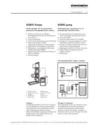
The Intelligent Front Module is a controller which can be used for measuring <strong>and</strong> controlling a variety of physical<br />
quantities. It consists of two parts, the display module <strong>and</strong> the IFM module. The desired function is configured in<br />
the menu. The controller can be used for proportional as well as limiting value controls.<br />
All settings are entered with the pushbuttons <strong>and</strong> shown on the display. Calibration <strong>and</strong> parameter adjustments<br />
are performed in the corresponding menus.<br />
It is m<strong>and</strong>atory to get familiar with the safety section on page 3 <strong>and</strong> to read carefully all warning <strong>instructions</strong> in<br />
order to avoid damages <strong>and</strong> malfunctions.<br />
The IFM controller is to be operated only by trained personnel well acquainted with this operation manual.
Bioengineering AG<br />
8636 Wald, Schweiz<br />
Telefon +41 (0)55 256 81 11<br />
Fax +41 (0)55 256 82 56<br />
0133-02 BA_IFM/Reg. 11 2 /19<br />
<strong>Installation</strong> <strong>and</strong> <strong>operating</strong> <strong>instructions</strong><br />
<strong>Chemical</strong> antifoam control /admittance probe<br />
Table of contents<br />
1 Safety <strong>instructions</strong> 3<br />
1.1 Safe <strong>and</strong> correct use 3<br />
2 General 4<br />
3 Scope of delivery 5<br />
4 Electronic measurement <strong>and</strong> control unit <strong>and</strong> probes 5<br />
4.1 Electronic measurement <strong>and</strong> control unit 6<br />
4.2 Adjusting the probe´s response sensitivity 6<br />
4.3 Probes 7<br />
4.4 Technical data 7<br />
5 Start-up, operation <strong>and</strong> antifoam agents 8<br />
5.1 Start-up 8<br />
5.2 Operation 8<br />
5.3 Antifoam agents 8<br />
6 Important control functions 9<br />
6.1 Selection of the control mode 9<br />
6.2 Setpoint adjustment <strong>and</strong> measuring value 10<br />
6.3 Manual mode: Filling of the transfer lines 10<br />
6.4 Profile Mode 10<br />
6.5 Control Behavior 11<br />
6.6 Consumption 11<br />
6.7 Trend graph 12<br />
6.8 Setting of alarms 13<br />
6.9 Password Setting 14<br />
6.10 Date / Time Setting 15<br />
6.11 Start up <strong>and</strong> Power-Failure 15<br />
6.12 Control Service Hours 15<br />
6.13 Contrast Setting on the Display 15<br />
7 Alarms <strong>and</strong> trouble shooting 16<br />
7.1 Alarms 16<br />
7.2 Messages 17<br />
8 Non-valid <strong>and</strong> pre-set functions 18
<strong>Installation</strong> <strong>and</strong> <strong>operating</strong> <strong>instructions</strong><br />
<strong>Chemical</strong> antifoam control /admittance probe<br />
Bioengineering AG<br />
8636 Wald, Schweiz<br />
Telefon +41 (0)55 256 81 11<br />
Fax +41 (0)55 256 82 56<br />
0133-02 BA_IFM/Reg. 11 3 /19<br />
1 Safety <strong>instructions</strong><br />
The <strong>instructions</strong> listed below contribute to the safety of the user.<br />
To secure safe operation, follow the safety <strong>instructions</strong> <strong>and</strong> read this manual carefully.<br />
Non-observance of these warning <strong>instructions</strong> can lead to malfunctions <strong>and</strong> defects of the device.<br />
Caution!<br />
Note!<br />
These notes help you to operate the universal controller properly <strong>and</strong> to fully use its possibilities.<br />
The electrical wiring must be connected by a licensed electrician.<br />
The power supply voltage must correspond to the voltage displayed on the rating plate.<br />
The IFM may be operated only by trained personnel familiar with the operation manual <strong>and</strong> the safety <strong>instructions</strong>.<br />
If the control cabinet is opened or the IFM is removed, parts which may carry dangerous high voltage are<br />
exposed. Exercise caution not to contact exposed metal parts during installation, interconnection or maintenance.<br />
Maintenance <strong>and</strong> other operations may only be performed by trained <strong>and</strong> qualified personnel familiar with the<br />
operation manual <strong>and</strong> the safety <strong>instructions</strong>.<br />
1.1 Safe <strong>and</strong> correct use<br />
The IFM controller may be used only for products listed in this manual <strong>and</strong> in the <strong>com</strong>ponent file, or in connection<br />
with devices <strong>and</strong> <strong>com</strong>ponents, which are checked resp. approved by Bioengineering AG for their <strong>com</strong>patibility. It<br />
may only be installed as stated the operation manual or according to the re<strong>com</strong>mendation of Bioengineering AG.
<strong>Installation</strong> <strong>and</strong> <strong>operating</strong> <strong>instructions</strong><br />
<strong>Chemical</strong> antifoam control /admittance probe<br />
Bioengineering AG<br />
8636 Wald, Schweiz<br />
Telefon +41 (0)55 256 81 11<br />
Fax +41 (0)55 256 82 56<br />
0133-02 BA_IFM/Reg. 11 4 /19<br />
2 General<br />
<br />
<br />
<br />
<br />
<br />
<br />
<br />
<br />
<br />
<br />
The antifoam control is achieved by a specially configured IFM universal controller. Besides st<strong>and</strong>ard setpoint<br />
control the IFM controller features a variety of functions in this st<strong>and</strong>ard configuration:<br />
– control modes such as setpoint, profile, cascade control<br />
– manual activation of control elements <strong>inc</strong>luding limitation of max/min output during control mode<br />
– trend graph <strong>and</strong> monitoring of consumption<br />
– alarm features<br />
– password protection of settings<br />
Measurement of the foam level is performed by an antifoam probe connected to the antifoam controller.<br />
To control the foam chemical antifoam agents are necessary. Therefore the antifoam controller has one ON/OFF<br />
output to control a peristaltic pump to dose the chemical antifoam agent. Alternatively a foam kill motor can be<br />
used to control the foam (NLF, LP, Pilot).<br />
The <strong>com</strong>plete parameter description is <strong>inc</strong>luded in the manual of the universal controller. The most important<br />
functions for the operation of the antifoam controller are described in detail in this manual.<br />
Note!<br />
The antifoam-controller does not require all possible functions of the universal controller. Chapter 8 describes<br />
which functions are not valid <strong>and</strong> therefore show no effect when being altered, <strong>and</strong> which functions were set<br />
by Bioengineering <strong>and</strong> should not be altered for proper use.
<strong>Installation</strong> <strong>and</strong> <strong>operating</strong> <strong>instructions</strong><br />
<strong>Chemical</strong> antifoam control /admittance probe<br />
Bioengineering AG<br />
8636 Wald, Schweiz<br />
Telefon +41 (0)55 256 81 11<br />
Fax +41 (0)55 256 82 56<br />
0133-02 BA_IFM/Reg. 11 5 /19<br />
Note!<br />
Note!<br />
The setpoint is defined in % output value. The on/off pump is active during the programmed setpoint %<br />
of the cycle time.<br />
As example:<br />
A 20 % set point value with 10 sec cycle time gives in 2 sec pump time <strong>and</strong> a 8sec pause. The cycle time <strong>and</strong> slew<br />
rate are defined in the function menu OUTPUT1.<br />
The measuring value is initially displayed in minutes of pump run-time <strong>and</strong> can be changed to a display<br />
of the volume of the antifoam agent consumed in the function menu CONSUMPTION 1.<br />
The IFM antifoam-controller is not a PID controller. This type of control is indicated by the SPO<br />
(= SetPoint equals Output) sign in the upper right corner of the information window.<br />
3 Scope of delivery<br />
– Autoclavable or sterilizable antifoam probe<br />
– Electronic measuring <strong>and</strong> control unit<br />
– Connecting cables<br />
4 Electronic measurement <strong>and</strong> control unit <strong>and</strong> probes<br />
The electronic measurement <strong>and</strong> control unit is <strong>inc</strong>orporated in a st<strong>and</strong>ard 19” <strong>com</strong>ponent module <strong>and</strong> is suitable<br />
for separate mounting or integration in a st<strong>and</strong>ard 19” cabinet.<br />
The Bioengineering foam sensor is adjustable in height <strong>and</strong> connected to the control unit.<br />
Special design features ensure that the sensor operates trouble-free, even under the conditions of extreme<br />
humidity prevailing in the fermenter.<br />
Perfectly satisfactory results are obtained with this st<strong>and</strong>ard system in most processes. We re<strong>com</strong>mend<br />
the use of the admittance system for cultures which are <strong>inc</strong>lined to pronounced surface <strong>and</strong> wall growth.<br />
If chemical antifoam agents should be avoided, optionally a mechanical foam-kill system is available additionally<br />
to or instead of the chemical system.
<strong>Installation</strong> <strong>and</strong> <strong>operating</strong> <strong>instructions</strong><br />
<strong>Chemical</strong> antifoam control /admittance probe<br />
Bioengineering AG<br />
8636 Wald, Schweiz<br />
Telefon +41 (0)55 256 81 11<br />
Fax +41 (0)55 256 82 56<br />
0133-02 BA_IFM/Reg. 11 6 /19<br />
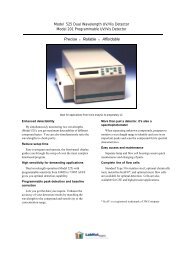
4.1 Electronic measurement <strong>and</strong> control unit<br />
Frontside<br />
Backside<br />
<br />
6<br />
8<br />
<br />
<br />
<br />
<br />
1<br />
<br />
<br />
<br />
<br />
9<br />
<br />
<br />
<br />
<br />
7<br />
3<br />
2<br />
4<br />
<br />
<br />
5<br />
1 IFM display modul<br />
2 Connector for antifoam probe<br />
3 I/O switch<br />
4 Main power supply 100-240 V, 50/60 Hz, fuses 1,6 A<br />
5 Dose pump or power supply, max. 1 A, 230 V (110 V)<br />
6 DIN-input/output socket for the current signals measured value <strong>and</strong> external set point for <strong>com</strong>munication<br />
with <strong>com</strong>puter-controlled measuring data acquisition <strong>and</strong> process control system.<br />
7 Controller output 4-20 mA for pumps<br />
8 Controller output 4-20 mA for valves or pumps<br />
9 Connector for Profibus (option)<br />
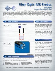
4.2 Adjusting the probe´s response sensitivity<br />
Pull the Anti Foam control unit out of the cabinet. On the top of the unit there is a hole for the adjusting tool.<br />
By turning this key counterclockwise the response sensitivity is <strong>inc</strong>reased, turning it clockwise will reduce<br />
the sensitivity (see the picture below).<br />
Adjusting tool
<strong>Installation</strong> <strong>and</strong> <strong>operating</strong> <strong>instructions</strong><br />
<strong>Chemical</strong> antifoam control /admittance probe<br />
Bioengineering AG<br />
8636 Wald, Schweiz<br />
Telefon +41 (0)55 256 81 11<br />
Fax +41 (0)55 256 82 56<br />
0133-02 BA_IFM/Reg. 11 7 /19<br />
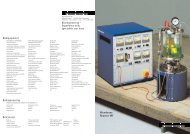
4.3 Probes<br />
Antifoam probes can be in-situ sterilizable or autoclavable, depending on the fermenter set-up. Antifoam probes<br />
operate on the pr<strong>inc</strong>iple of conductive boundary status detection. The bottom of the fermenter <strong>and</strong> the probe<br />
form two electrodes, between which a small A.C. voltage exists. As soon as the conductive foam touches the tip<br />
of the probe, a small current flows <strong>and</strong> causes a relay to respond via an amplifier circuit.<br />
This system produces ideal results even with cultures wich have a pronounced tendency towards surface <strong>and</strong> wall<br />
growth. Special design <strong>and</strong> measuring techniques were used to produce a foam detection device wich operates<br />
faultlessly even with a sensor wich is overgrown by a conductive coating.<br />
Note!<br />
Note!<br />
The probe does not work properly in deionized water.<br />
The function of the probe can only be tested when it is installed in the fermenter.<br />
foam<br />
medium<br />
4.4 Technical data<br />
Antifoam-transmitter<br />
Sensitivity<br />
Response time<br />
≤ 0.1 pF<br />
approx. 0.2 sec.<br />
Probes<br />
See data sheet
<strong>Installation</strong> <strong>and</strong> <strong>operating</strong> <strong>instructions</strong><br />
<strong>Chemical</strong> antifoam control /admittance probe<br />
Bioengineering AG<br />
8636 Wald, Schweiz<br />
Telefon +41 (0)55 256 81 11<br />
Fax +41 (0)55 256 82 56<br />
0133-02 BA_IFM/Reg. 11 8 /19<br />
5 Start-up, operation <strong>and</strong> antifoam agents<br />
5.1 Start-up<br />
– Check for transport or storage damages<br />
– Mount probe onto the fermenter lid.<br />
– Connect probe cable to the controller <strong>and</strong> probe<br />
– Switch on controller with I/O switch on the backside.<br />
– Check if the pump for the antifoam agent is connected on the backside of the controller.<br />
– Sterilization: Sterilizable probes are sterilized in situ with the filled fermenter.<br />
– Autoclaving: Autoclavable probes are sterilized with the filled fermenter in an autoclave.<br />
Therefore the cable is removed from the probe.<br />
Note!<br />
Always make sure that the probe is clean before starting the sterilization. Overgrowth of the probe can simulate<br />
constant foam contact. This would lead to continuous dosage of antifoam agent.<br />
5.2 Operation:<br />
– Connect sterile antifoam agent to the fermenter.<br />
– Ensure that the antifoam agent is installed correctly to be dosed to the fermentation broth<br />
<strong>and</strong> check pump direction or pressurization of feed vessels.<br />
– Check if the settings of the controller are correct.<br />
– Select desired operation mode (Information window Information line control mode<br />
Set control mode with ).<br />
5.3 Antifoam agents<br />
Often used antifoam agents are:<br />
– Polyethylene glycol PEG 200-2000 (especially PEG-1000)<br />
– Antifoam B (based on silicon oil): dilute 1: 2<br />
– Antifoam emulsion SI-B (based on silicon oil)<br />
– Propylene glycol 2020<br />
– Pluronic F-68: suitable for mammalioan or insect cell cultures<br />
It is re<strong>com</strong>mended to add a little antifoam agent (e.g. 1 ml/l) to the fermentation broth before sterilization<br />
to avoid foaming during heating.<br />
Note!<br />
All antifoam agents can be autoclaved in concentrated form. During autoclaving the antifoam emulsion<br />
could break. Therefore it is re<strong>com</strong>mended to insert a magnetic stirrer before autoclaving to dissolve precipitates<br />
by vigorous stirring if necessary. Sterilized antifoam agent can be stored at room temperature.<br />
Antifoam agents may have a negative effect in down-stream processes.
<strong>Installation</strong> <strong>and</strong> <strong>operating</strong> <strong>instructions</strong><br />
<strong>Chemical</strong> antifoam control /admittance probe<br />
Bioengineering AG<br />
8636 Wald, Schweiz<br />
Telefon +41 (0)55 256 81 11<br />
Fax +41 (0)55 256 82 56<br />
0133-02 BA_IFM/Reg. 11 9 /19<br />
6 Important control functions<br />
Information window:<br />
Alert ALRT<br />
Message OUTR<br />
Alarm ALRM<br />
Measuring value display<br />
Setpoint display<br />
Status display<br />
<br />
<br />
<br />
<br />
<br />
<br />
<br />
<br />
}<br />
}<br />
No remote setpoint<br />
Hint panels (Headline)<br />
Setpoint equals output<br />
Unit: Measuring value (= Consumption)<br />
Unit: Setpoint (= Output)<br />
Information line (Bottom line) for:<br />
<br />
Date <strong>and</strong> Time<br />
<br />
Output value (% opening of value, % performance of pump)<br />
<br />
Control mode<br />
<br />
Setpoint<br />
<br />
Execute<br />
Note!<br />
The control functions important for antifoam-control are explained in detail in this chapter.<br />
Functions set by Bioengineering, which should not be altered <strong>and</strong> functions not valid for antifoam control<br />
are indicated in chapter 8. All functions of the controller are listed in the manual of the universal controller.<br />
6.1 Selection of control mode<br />
The control mode is changed in the information window:<br />
Select the information line Control mode in the information window with .<br />
Select the desired control mode with .<br />
Control modes are:<br />
OFF: The control is de-activated. In the OFF mode the NRSP lamp is illuminated. The Remote setpoint is not valid.<br />
MANUAL: The % output of the controller is entered on the display. The output 0-100% means the pump/valve<br />
setting from minimum to the maximum (100%). When the control mode MANUAL is selected the output<br />
of the controller can be adjusted in the information line Output.<br />
CONTR.: Setpoint control is selected. The display shows Setp. 1 if internal setpoint is selected,<br />
Setp. 2 if an external setpoint is selected (via PLC), or REMOTE if a remote setpoint is selected (via software).<br />
PROFILE: A predefined profile is activated. For the programming of the profile see chapter 6.4.<br />
STERILIZE: Controller switches to control mode STERILIZE. This mode opens the pump/valve outputs.<br />
It is used only for specially defined applications.<br />
Note!<br />
If the operation modes CONTROLLED or PROFILE are selected, they will only be active when the probe is in contact<br />
with the foam. When the probe is not in contact with the foam, in the status display EXT.OFF is displayed.
<strong>Installation</strong> <strong>and</strong> <strong>operating</strong> <strong>instructions</strong><br />
<strong>Chemical</strong> antifoam control /admittance probe<br />
Bioengineering AG<br />
8636 Wald, Schweiz<br />
Telefon +41 (0)55 256 81 11<br />
Fax +41 (0)55 256 82 56<br />
0133-02 BA_IFM/Reg. 11 10 /19<br />
6.2 Setpoint adjustment <strong>and</strong> measuring value<br />
The setpoint is displayed in the information window as % output of the controller. This means, with the setpoint<br />
the output <strong>and</strong> therefore the pumping capacity is selected between 0 <strong>and</strong> 100 %: an on/off pump is delivered<br />
as st<strong>and</strong>ard 0 <strong>and</strong> 100 % output signals correspond to the calculation of cycle times.<br />
To alter a setpoint the information line Setpoint is selected with in the information window.<br />
With the desired output is chosen <strong>and</strong> it is confirmed with . The measuring value is initially displayed<br />
in minutes of pump or valve activation. To obtain a volume display of antifoam agent dosed, the volume must be<br />
calibrated in the function menu consumption 1 (see chapter 6.6).<br />
6.3 Manual mode: Filling of the transfer lines<br />
The MANUAL control mode is selected as described in chapter 6.1. To fill the antifoam transfer lines select<br />
positive % output value. Put the output of the controller to 0 when the line is full, but before the antifoam agent<br />
is inserted into the vessel.<br />
6.4 Profile mode<br />
The profile function is especially useful for the antifoam control, because the dosage of the antifoam agent<br />
can be delayed <strong>and</strong>/or adjusted with the profile function.<br />
To save chemicals the dosage can be delayed for e.g. 1 min after the first contact of foam before dosage of the<br />
antifoam agent starts. If there is still foaming after 1 min, more <strong>and</strong> more antifoam agent is dosed dependent<br />
on the time the foaming lasts. This ensures that the dosage is adjusted to the intensity of the foaming <strong>and</strong> no<br />
chemicals are wasted during short-time foaming which subsides without addition of chemicals. At the beginning<br />
of each contact of the probe with foam the profile is started new.<br />
To program a profile enter the group menu PARA by pressing <strong>and</strong> then select PARA with <strong>and</strong> confirm<br />
with . Then select PROFILE by pressing . With the duration the period of time is defined within<br />
which the setpoint (End val.) is reached. If the setpoint should be maintained, another step with the same<br />
setpoint <strong>and</strong> a later duration must be defined.
<strong>Installation</strong> <strong>and</strong> <strong>operating</strong> <strong>instructions</strong><br />
<strong>Chemical</strong> antifoam control /admittance probe<br />
Bioengineering AG<br />
8636 Wald, Schweiz<br />
Telefon +41 (0)55 256 81 11<br />
Fax +41 (0)55 256 82 56<br />
0133-02 BA_IFM/Reg. 11 11 /19<br />
The given example is programmed by setting SLOPE, END VAL 1 <strong>and</strong> END VAL 2 to 0 <strong>and</strong> DURATION 2 to 0.017 h.<br />
END VAL3 is set to the desired setpoint (e.g. 100 %). The time within the END VAL 3 is reached (e. g. 1 h),<br />
is defined by setting the DURATION 3 (see also figure).<br />
<br />
<br />
<br />
<br />
<br />
<br />
The functions are as follows:<br />
SLOPE: Slope (S) is the calculated slope with which the first setpoint (end value 1) is reached (in hours).<br />
If the value is set to zero, end value is reached as fast as possible. The slope can be rising or falling.<br />
END VAL. 1: Setpoint (EV 1) for the first step<br />
DURATION 2: Duration (D2) of the second step (in hours)<br />
END VAL. 2: Setpoint (EV 2) for the second step<br />
Ten steps can be entered. If a step has the duration 0, the program stops <strong>and</strong> the last setpoint is kept.<br />
DURAT. 10: Duration of the tenth step (in hours).<br />
END VAL. 10: Setpoint for the tenth step.<br />
6.5 Control Behavior<br />
In the group menu choose function menu CONTR PAR <strong>and</strong> select BEHAVIOR.<br />
BEHAVIOR: (Protected with password 1): This function defines the behavior of the controller when it is switched<br />
from manual to controlled mode.<br />
CLOSE OUT: The output starts at 0% before the PID calculations are initiated.<br />
Thus the acid <strong>and</strong> the base pump are deactivated during the switch over before starting the control.<br />
KEEP OUT: The acid <strong>and</strong> base pumps change continuously (shock-free) from the present value into<br />
the new entity.<br />
6.6 Consumption<br />
The antifoam-controller enables the monitoring of antifoam agent consumption.<br />
In the function menu CONSUMPT.1 the consumption of antifoam agent is displayed <strong>and</strong> can be calibrated.<br />
To enter the function menu enter the group menu STAT by pressing <strong>and</strong> then select STAT with <strong>and</strong><br />
confirm with . Then select CONSUMPT. 1 by pressing .<br />
For the viewing of the consumption of antifoam agent CONS. TOT is selected in the function menu CONSUMPT. 1.<br />
The total consumption is displayed in ml or l (as chosen in UNITS), only if the parameter CONS./M. was set correctly.
<strong>Installation</strong> <strong>and</strong> <strong>operating</strong> <strong>instructions</strong><br />
<strong>Chemical</strong> antifoam control /admittance probe<br />
Bioengineering AG<br />
8636 Wald, Schweiz<br />
Telefon +41 (0)55 256 81 11<br />
Fax +41 (0)55 256 82 56<br />
0133-02 BA_IFM/Reg. 11 12 /19<br />
In the function RESET the consumption is set to zero with<br />
when the RES. MODE is set to MANUAL.<br />
The reset mode is selected in RES. MODE (Protected with password 1): LOCKED: the consumption cannot be reset;<br />
MANUAL: the consumption is set to zero with reset; or AUTO: The consumption is set to zero every time the controller<br />
is switched on.<br />
Initially the consumption values are set to minutes of dosing times of the pump. To obtain actual volumes<br />
of antifoam agent two steps are necessary:<br />
– External calibration of the pump:<br />
The volume of liquid delivered by the pump per minute at 100 % output (e.g. set in the manual mode)<br />
is determined with a measuring cylinder <strong>and</strong> a watch or other suitable equipment.<br />
– Setting of the following parameters (protected by password 1) in the function menu CONSUMPT. 1:<br />
FORMAT: The format of the consumption is defined as places before <strong>and</strong> after the <strong>com</strong>ma (e.g. XXX.X).<br />
UNITS: The unit for the consumption is selected.<br />
CONS./M: S<strong>inc</strong>e the calculation of the consumption is based on the measurement of time, the exact consumption<br />
in the respective output (which has been calibrated as described above) per minute at 100% pump capacity must<br />
be inserted.<br />
MIN. VALUE: A minimum volume (or whatever was selected in UNITS) of antifoam agent in the feed bottle<br />
or tank is defined (usually 0).<br />
MAX. VALUE: A maximum volume (or whatever was selected in UNITS) of antifoam agent in the feed bottle<br />
or tank is defined. (usually filling level of antifoam agent).<br />
Note!<br />
With the last two functions also the alarm values are defined.<br />
6.7 Trend graph<br />
The IFM-controller enables the monitoring of the parameter values over a defined period of time (trend).<br />
The trend graph is displayed when is pressed in the information window. To return to the information window<br />
is pressed.<br />
To select the duration of the trend graph enter the group menu STAT by pressing <strong>and</strong> then select STAT<br />
with <strong>and</strong> confirm with . Then select TREND CONF by pressing . The length of the trend graph can<br />
now be altered.
<strong>Installation</strong> <strong>and</strong> <strong>operating</strong> <strong>instructions</strong><br />
<strong>Chemical</strong> antifoam control /admittance probe<br />
Bioengineering AG<br />
8636 Wald, Schweiz<br />
Telefon +41 (0)55 256 81 11<br />
Fax +41 (0)55 256 82 56<br />
0133-02 BA_IFM/Reg. 11 13 /19<br />
Note!<br />
Note!<br />
6.8 Setting of alarms<br />
High <strong>and</strong> low alarms can be set. Their display <strong>and</strong> possible causes are described in chapter 8.<br />
Alarms are only active in the control modes CONTROLLED <strong>and</strong> PROFILE.<br />
For the alarms the consumption of the antifoam agent is selected.<br />
Therefore the settings in the function menu consumpt 1 must also be considered when setting the alarms.<br />
LOW ALARM: Defines the lower alarm limit (normally not used for antifoam control).<br />
L. A. OUTP (Low alarm output):<br />
OFF: The low alarm is switched off.<br />
NO OUTPUT: No external signal is generated<br />
ALARM 1*: External signal option 1 is selected (e.g. lamp)<br />
ALARM 2*: External signal option 2 is selected (e.g. acoustic sound)<br />
ALARM 1 + 2*: Both external signal options are selected.<br />
* The lamp ALRM at the display module is always illuminated when an alarm is active, pregardless of the settings<br />
of external alarm signals. External signal options are not <strong>inc</strong>luded in the supply as st<strong>and</strong>ard.<br />
HIGH ALARM: Defines the upper alarm limit in the units set in CONSUMPT 1<br />
(e.g. is set to give alarm before the feed-bottle/tank is empty).<br />
H. A. OUTP (High alarm output): Same as L. A. OUTP.<br />
DEV. ALARM: Defines the deviation alarm limit (normally not used for antifoam control).<br />
D. A. OUTP (Deviation alarm output) used to switch alarm on <strong>and</strong> off: As L. A. OUTP.<br />
ALARM 1: Direct/Reverse<br />
ALARM 2: Direct/Reverse
<strong>Installation</strong> <strong>and</strong> <strong>operating</strong> <strong>instructions</strong><br />
<strong>Chemical</strong> antifoam control /admittance probe<br />
Bioengineering AG<br />
8636 Wald, Schweiz<br />
Telefon +41 (0)55 256 81 11<br />
Fax +41 (0)55 256 82 56<br />
0133-02 BA_IFM/Reg. 11 14 /19<br />
6.9 Password Setting<br />
Some function menus such as CALIB MEAS <strong>and</strong> some functions such as behavior are password protected.<br />
To activate or change the password, enter group menu <strong>and</strong> select the function menu PASSWORD.<br />
Menu PASSWORD<br />
ACTIVATE: If the password is entered, it stays active for further operations (with temporal limitation).<br />
DEACTIVATE: The entered password is deactivated <strong>and</strong> must be entered again for operations requiring<br />
the password.<br />
CHANGE PW: To change password 1 the following steps have to be performed:<br />
1. CHANGE PW: .<br />
2. ENTER THE PASSWORD:<br />
Enter the old password (six-digit figure; always 000000 before first change) with <strong>and</strong><br />
(numbers <strong>and</strong> letters can be entered) <strong>and</strong> confirm with .<br />
<br />
<br />
THE PASSWORD HAS BEEN ACCEPTED: Confirm with . If the wrong password has been entered the following<br />
message appears: THE PASSWORD IS NOT ACCEPTED PRESS MENU TO ABORT.<br />
The function is aborted with .<br />
3. ENTER THE NEW PASSWORD: Enter the new password with <strong>and</strong> <strong>and</strong> confirm with .<br />
4. ENTER THE NEW PASSWORD AGAIN: Enter the new password again with <strong>and</strong> <strong>and</strong> confirm<br />
with .<br />
THE NEW PASSWORD HAS BEEN STORED: The new password is now active.<br />
5. Confirm with . If an error has occurred during the confirmation of the password the following message<br />
appears: THE PASSWORD IS NOT ACCEPTED PRESS MENU TO ABORT.<br />
The function is aborted with .<br />
Caution!<br />
In the group menus protected with password 2 parameters essential for the basic functions of the controller<br />
are defined. These parameters should not be changed on any account. Therefore password 2 can only be ordered<br />
by contacting Bioengineering AG.
<strong>Installation</strong> <strong>and</strong> <strong>operating</strong> <strong>instructions</strong><br />
<strong>Chemical</strong> antifoam control /admittance probe<br />
Bioengineering AG<br />
8636 Wald, Schweiz<br />
Telefon +41 (0)55 256 81 11<br />
Fax +41 (0)55 256 82 56<br />
0133-02 BA_IFM/Reg. 11 15 /19<br />
6.10 Date <strong>and</strong> Time Setting (password 1 protected)<br />
Enter group menu OPTI <strong>and</strong> select function menu DATE+TIME.<br />
SUMMERTIME: To select (+ 1 HOUR) or deactivate (OFF) summertime.<br />
DATE FORM: Defines date display (DD.MMM or MMM.DD).<br />
SECONDS, MINUTES, DAY, MONTH, YEAR: Time <strong>and</strong> date are set.<br />
ADJ. CLOCK: Running errors of the clock s<strong>inc</strong>e initialization are <strong>com</strong>pensated.<br />
INIT CLOCK: Initializes the clock at first adjustment.<br />
SOFTW. DATE: Software version<br />
Note!<br />
6.11 Start-up <strong>and</strong> Power-Failure<br />
PWRON-MODE: (Protected by password 1): Defines settings of the control mode after start-up or power-failure:<br />
OFF: The controller is switched off.<br />
MANUAL: Manual mode is started.<br />
CONTROLLED: Controlled mode is started.<br />
PROFILE: The profile program is started.<br />
CASCADE: This control mode is inactive for antifoam control <strong>and</strong> should therefore not be selected.<br />
LATEST: The control mode selected before the start-up or power-failure are started.<br />
If external control via software is used, all remote setpoints are active after failure of the <strong>com</strong>puter. If the startup<br />
of the <strong>com</strong>puter fails <strong>and</strong> local control is required, it is re<strong>com</strong>mended to switch off the interface or deactivate<br />
the external control by setting AUTO RSP in the function menu CONTROL PAR to OFF.<br />
6.12 Control service hours<br />
The running time of the controller is displayed in group menu , function menu VARIOUS.<br />
6.13 Contrast Setting on the Display<br />
To set the contrast on the display is pressed while the controller is switched off <strong>and</strong> on with the I/O switch<br />
on the backside. The following display appears:<br />
<br />
<br />
The contrast is altered with until everything on the display is clearly visible.<br />
To get back to the information window press .<br />
Caution!<br />
Please make sure that at the end of this procedure the address is set to ADDR: A.<br />
Otherwise the menu of the controller will not be loaded. If necessary the address is set back to A with .
<strong>Installation</strong> <strong>and</strong> <strong>operating</strong> <strong>instructions</strong><br />
<strong>Chemical</strong> antifoam control /admittance probe<br />
Bioengineering AG<br />
8636 Wald, Schweiz<br />
Telefon +41 (0)55 256 81 11<br />
Fax +41 (0)55 256 82 56<br />
0133-02 BA_IFM/Reg. 11 16 /19<br />
7 Alarms <strong>and</strong> trouble shooting<br />
7.1 Alarms<br />
<br />
<br />
<br />
<br />
<br />
<br />
<br />
<br />
ALARM<br />
Description<br />
Possible Cause<br />
Action<br />
HIGHER ALARM LIMIT EXCEEDED<br />
The high alarm limit predefined<br />
in the function menu ALARMS has<br />
been exceeded. When all settings<br />
are correct, the storage bottle is<br />
nearly empty.<br />
Alarm setting <strong>and</strong> consumption<br />
setting do not correspond<br />
Storage bottle/feed vessel of antifoam<br />
agent is (nearly) empty<br />
Probe sends constant signal<br />
to controller<br />
Check settings<br />
Refill bottle<br />
Check if probe is overgrown or<br />
check level of probe.<br />
More foam is formed than can be<br />
destroyed<br />
Change antifoam agent or if a<br />
profile is used change the settings<br />
of the profile, decrease the level<br />
of the medium or enhance pump<br />
capacity by:<br />
a) <strong>inc</strong>reasing the setpoint,<br />
b) using tubes with bigger<br />
diameters,<br />
c) using a pump with a higher<br />
capacity<br />
Alarms are displayed by the corresponding line on the display <strong>and</strong> by a flashing LED lamp.<br />
The alarms are confirmed with .<br />
If the problem is eliminated simultaneously the LED lamp is extinguished. If the alarm is only acknowledged<br />
but the corresponding problem is not eliminated the LED lamp stops blinking <strong>and</strong> glows continuously.
<strong>Installation</strong> <strong>and</strong> <strong>operating</strong> <strong>instructions</strong><br />
<strong>Chemical</strong> antifoam control /admittance probe<br />
Bioengineering AG<br />
8636 Wald, Schweiz<br />
Telefon +41 (0)55 256 81 11<br />
Fax +41 (0)55 256 82 56<br />
0133-02 BA_IFM/Reg. 11 17 /19<br />
7.2 Messages<br />
<br />
<br />
<br />
<br />
<br />
<br />
<br />
<br />
Message Possible Cause Action<br />
ANALOG OUTPUT 1<br />
IS DISCONNECTED<br />
Pump/valve is not connected<br />
Check connection of pump<br />
PULSE OUTPUT 1<br />
HAS SHORT CIRCUIT<br />
Pulse output 1 has a short circuit<br />
Check wiring<br />
ALARM OUTPUT<br />
HAS SHORT CIRCUIT<br />
Alarm output has a short circuit<br />
Check wiring<br />
Messages are displayed by the corresponding line on the display <strong>and</strong> by a flashing LED lamp.<br />
The alarms are confirmed with .<br />
If the problem is eliminated simultaneously the LED lamp is extinguished. If the alarm is only acknowledged<br />
but the corresponding problem is not eliminated the LED lamp stops blinking <strong>and</strong> glows continuously.
<strong>Installation</strong> <strong>and</strong> <strong>operating</strong> <strong>instructions</strong><br />
<strong>Chemical</strong> antifoam control /admittance probe<br />
Bioengineering AG<br />
8636 Wald, Schweiz<br />
Telefon +41 (0)55 256 81 11<br />
Fax +41 (0)55 256 82 56<br />
0133-02 BA_IFM/Reg. 11 18 /19<br />
Note!<br />
8 Non-valid <strong>and</strong> pre-set functions<br />
This chapter describes which functions are not valid <strong>and</strong> therefore show no effect when being altered<br />
(marked with: “Not valid for antifoam control”) <strong>and</strong> which functions were set by Bioengineering<br />
(marked with: “Set by Bioengineering”).<br />
Group menu <br />
Function menu CONTRL PAR<br />
TEMP. COMP.: Not valid for antifoam-control.<br />
MAN. T. COMP: Not valid for antifoam -control<br />
AUTO RSP: Set by Bioengineering<br />
Function menu STERIL PAR<br />
Set by Bioengineering<br />
Function menu CASC. INP<br />
Not valid for antifoam-control.<br />
Function menu PID PARAMS<br />
Not valid for antifoam-control.<br />
Function menu CONTR. SET<br />
Set by Bioengineering<br />
Function menu INPUT PAR<br />
Set by Bioengineering<br />
Function menu OUTPUT PAR<br />
Set by Bioengineering.<br />
Function menu OUTPUT 1<br />
Set by Bioengineering.<br />
Function menu KOBIO 1<br />
Not valid for antifoam-control.<br />
Function menu OUTPUT 2<br />
Not valid for antifoam-control.<br />
Function menu KOBIO 2<br />
Not valid for antifoam-control<br />
Group menu <br />
Function menu CONSUMPT. 2<br />
Not valid for antifoam-control.
<strong>Installation</strong> <strong>and</strong> <strong>operating</strong> <strong>instructions</strong><br />
<strong>Chemical</strong> antifoam control /admittance probe<br />
Bioengineering AG<br />
8636 Wald, Schweiz<br />
Telefon +41 (0)55 256 81 11<br />
Fax +41 (0)55 256 82 56<br />
0133-02 BA_IFM/Reg. 11 19 /19<br />
Group menu <br />
Function menu CALIB. MEAS.<br />
Set by Bioengineering<br />
Function menu CALIB. RSP<br />
Set by Bioengineering<br />
Function menu CALIB. CASC<br />
Set by Bioengineering<br />
Function menu PREV. CALIB<br />
Displays the offset <strong>and</strong> the slope of the three calibrations (has only display function <strong>and</strong> cannot be adjusted).<br />
Group menu <br />
Function menu CONFIGUR.<br />
Set by Bioengineering<br />
Function menu SETTINGS<br />
Set by Bioengineering