X75 Aluminium Flap Valve Pump Design Level 7 - Blagdon Pump
X75 Aluminium Flap Valve Pump Design Level 7 - Blagdon Pump
X75 Aluminium Flap Valve Pump Design Level 7 - Blagdon Pump

Create successful ePaper yourself
Turn your PDF publications into a flip-book with our unique Google optimized e-Paper software.
Table of Contents<br />
SERVICE AND OPERATING MANUAL<br />
Original Instructions<br />
<strong>X75</strong> <strong>Aluminium</strong> <strong>Flap</strong> <strong>Valve</strong> <strong>Pump</strong><br />
<strong>Design</strong> <strong>Level</strong> 7<br />
Engineering Data and Performance Curve............................................................ 1<br />
Explanation of <strong>Pump</strong> Nomenclature ...................................................................... 2<br />
Dimensions ............................................................................................................ 3<br />
Principle of Operation ............................................................................................ 4<br />
Installation and Start-Up ........................................................................................ 4<br />
Air Supply .............................................................................................................. 4<br />
Air Inlet & Priming .................................................................................................. 4<br />
Installation Guide ................................................................................................... 5<br />
Externally Serviceable Air Distribution System .......................................................... 6<br />
Air Exhaust ............................................................................................................ 7<br />
Between Uses ....................................................................................................... 7<br />
Check <strong>Valve</strong> Servicing ........................................................................................... 7<br />
Diaphragm Servicing ............................................................................................. 7<br />
Pilot <strong>Valve</strong> .............................................................................................................. 8<br />
Pilot <strong>Valve</strong> Actuator ................................................................................................ 8<br />
Service Instructions: Troubleshooting ................................................................... 9<br />
Warranty ................................................................................................................ 9<br />
Grounding The <strong>Pump</strong> .......................................................................................... 10<br />
Important Safety Information ............................................................................... 11<br />
Recycling ............................................................................................................. 11<br />
Material Codes .................................................................................................... 12<br />
Composite Repair Parts List ...........................................................................13-14<br />
Composite Repair Drawing.................................................................................. 15<br />
CE Declaration of Conformity - Machinery .......................................................... 16<br />
CE Declaration fo Conformity - ATEX .................................................................. 17<br />
IDEX <strong>Pump</strong> Technologies (Ireland) Ltd., • A Unit of IDEX Corporation, R79, Shannon, Co Clare, IRELAND.<br />
• TEL: +353 61 471933 FAX: +353 61 475046 www.blagdonpump.com • e-Mail: sales@blagdonpump.com<br />
x75afvmdl7sm-rev0411<br />
See page 17 for<br />
II ATEX 2GD ratings T5
SUCTION/DISCHARGE PIPE SIZE<br />
3" 150# ANSI Flange<br />
HEAD<br />
BAR<br />
7<br />
6<br />
5<br />
4<br />
3<br />
2<br />
1<br />
0<br />
PSI<br />
100<br />
90<br />
80<br />
70<br />
60<br />
50<br />
40<br />
30<br />
20<br />
CAPACITY<br />
(0 to 988 liters per minute)<br />
AIR CONSUMPTION<br />
SCFM (M<br />
20(34) 40(68)<br />
60(101.9)<br />
3 /hr)<br />
100 PSI<br />
80 PSI<br />
60 PSI<br />
40 PSI<br />
20 PSI Air Inlet Pressure<br />
80(135.9)<br />
<strong>X75</strong> <strong>Aluminium</strong> <strong>Flap</strong> <strong>Valve</strong> <strong>Pump</strong><br />
<strong>Design</strong> <strong>Level</strong> 7<br />
Air-Operated<br />
Double Diaphragm <strong>Pump</strong><br />
ENGINEERING, PERFORMANCE<br />
& CONSTRUCTION DATA<br />
AIR VALVE<br />
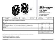
No-lube, no-stall<br />
design<br />
100(169.9)<br />
SOLIDS-HANDLING<br />
Up to nearly 3" (75mm)<br />
<strong>Pump</strong>s are designed to be powered only by compressed air.<br />
See page 17<br />
II for 2GD ATEX ratings T5<br />
HEADS UP TO<br />
125 psi or 289 ft. of water<br />
(8.8 Kg/cm 2 or 88 meters)<br />
MODEL HDF3-A Performance Curve<br />
Performance based on the following: elastomer fitted pump, flooded suction,<br />
water at ambient conditions. The use of other materials and varying hydraulic<br />
conditions may result in deviations in excess of 5%.<br />
10<br />
0<br />
0 20 40 60 80 100 120 140 160 180 200 220 240 260<br />
U.S. Gallons per minute<br />
0 100 200 300 400 500 600 700 800 900 1000<br />
Liters per minute<br />
CAPACITY<br />
120(203.9)<br />
x75afvmdl7sm-rev0411 Page 1
TYPICAL CODE= <strong>X75</strong>. 01. A. A. F. T. B. B. S.<br />
Model - <strong>X75</strong><br />
<strong>Design</strong> <strong>Level</strong><br />
Wetted Components<br />
A: <strong>Aluminium</strong><br />
Non-Wetted Components<br />
A: <strong>Aluminium</strong><br />
<strong>Valve</strong> Type<br />
F: <strong>Flap</strong><br />
Suction Orientation<br />
T: Top<br />
II 2G c T5<br />
II 3/2 G c T5<br />
II 2D c T100°C<br />
II 2GD T5<br />
Note: Type Examination<br />
Maximum delivery: 998 ltrs/min<br />
Max. working pressure: 8.6 bar<br />
Max. solid particle size: 75mm<br />
Air inlet: 1/2” NPT<br />
Temperatur limits: Determined by elastomers<br />
Fluid inlet/outlet: 3" ANSI Flange<br />
<strong>Valve</strong> Seats:<br />
S: Stainless Steel<br />
<strong>Flap</strong> <strong>Valve</strong>s<br />
B: Nitrile<br />
N: Neoprene<br />
R: Santoprene<br />
H: Hytrel<br />
P: Polyurethane<br />
Diaphragms<br />
B: Nitrile<br />
R: Santoprene<br />
N: Neoprene<br />
Intallation: Surface mounted<br />
Accessories included: Metal Exhaust air silencer<br />
Shipping weights A: 92kg<br />
x75afvmdl7sm-rev0411 Page 2
Dimensions:<br />
Dimensions are ± 1/8"<br />
Figures in parenthesis = millimeters<br />
x75afvmdl7sm-rev0411 Page 3
PRINCIPLE OF PUMP OPERATION<br />
This flap swing check valve pump is powered by compressed air and is a 1:1 pressure<br />
ratio design. It alternately pressurizes the inner side of one diaphragm chamber, while<br />
simultaneously exhausting the other inner chamber. This causes the diaphragms, which<br />
are connected by a common rod, to move endwise. Air pressure is applied over the<br />
entire surface of the diaphragm, while liquid is discharged from the opposite side. The<br />
diaphragm operates under a balanced condition during the discharge stroke, which<br />
allows the unit to be operated at discharge heads over 200 feet (61 meters) of water<br />
head.<br />
Since the diaphragms are connected by a common rod, secured by plates to the<br />
center of the diaphragms, one diaphragm performs the discharge stroke, while the other<br />
is pulled to perform the suction stroke in the opposite chamber.<br />
For maximum diaphragm life, keep the pump as close to the liquid being pumped as<br />
possible. Positive suction head in excess of 10 feet of liquid (3.048 meters) may require<br />
a back pressure regulating device. This will maximize diaphragm life.<br />
Alternate pressuring and exhausting of the diaphragm chamber is performed by<br />
means of an externally mounted, pilot operated, four-way spool type air distribution<br />
valve. When the spool shifts to one end of the valve body, inlet air pressure is applied to<br />
one diaphragm chamber and the other diaphragm chamber exhausts. When the spool<br />
shifts to the opposite end of the valve body, the porting of chambers is reversed. The air<br />
distribution valve spool is moved by an internal pilot valve which alternately pressurizes<br />
one side of the air distribution valve spool, while exhausting the other side. The pilot<br />
valve is shifted at each end of the diaphragm stroke by the diaphragm plate coming in<br />
contact with the end of the pilot valve spool. This pushes it into position for shifting of<br />
the air distribution valve.<br />
The chambers are manifolded together with a suction and discharge check valve for<br />
each chamber, maintaining flow in one direction through the pump.<br />
INSTALLATION & START-UP<br />
Locate the pump as close to the product being pumped as possible, keeping suction<br />
line length and number of fittings to a minimum. Do not reduce line size.<br />
For installations of rigid piping, short flexible sections of hose should be installed<br />
between pump and piping. This reduces vibration and strain to the piping system. A<br />
pulsation dampener is recommended to further reduce pulsation in flow.<br />
This pump was tested at the factory prior to shipment and is ready for operation. It is<br />
completely self-priming from a dry start for suction lifts of 20 feet (6.096 meters) or less.<br />
For suction lifts exceeding 20 feet of liquid, fill the chambers with liquid prior to priming.<br />
AIR SUPPLY<br />
Air supply pressures cannot exceed 125 psi (8.61 bar). Connect the pump air inlet<br />
to an air supply of sufficient capacity and pressure required for desired performance.<br />
When the air line is solid piping, use a short length of flexible hose (not less than 3/4"<br />
(19mm) in diameter) between pump and piping to eliminate strain to pipes.<br />
AIR INLET & PRIMING<br />
For start-up, open an air valve approximately 1/2" to 3/4" turn. After the unit primes,<br />
an air valve can be opened to increase flow as desired. If opening the valve increases<br />
cycling rate, but does not increase flow rate, cavitation has occurred, and the valve<br />
should be closed slightly.<br />
For the most efficient use of compressed air and the longest diaphragm life, throttle<br />
the air inlet to the lowest cycling rate that does not reduce flow.<br />
SERVICE AND OPERATING MANUAL<br />
<strong>X75</strong> <strong>Aluminium</strong> <strong>Flap</strong> <strong>Valve</strong> <strong>Pump</strong><br />
<strong>Design</strong> <strong>Level</strong> 7<br />
See page 17 for<br />
II ATEX 2GD ratings T5<br />
x75afvmdl7sm-rev0411 Page 4
Available from<br />
Distributor<br />
Available from<br />
Warren Rupp<br />
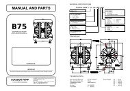
INSTALLATION GUIDE<br />
Bottom Discharge <strong>Flap</strong> <strong>Valve</strong> Unit<br />
CAUTION<br />
The air exhaust should be<br />
piped to an area for safe<br />
disposition of the product<br />
being pumped, in the event<br />
of a diaphragm failure.<br />
x75afvmdl7sm-rev0411 Page 5
AIR VALVE LUBRICATION<br />
The pump’s pilot valve and main air valve assemblies are designed to operate<br />
WITHOUT lubrication. This is the preferred mode of operation. There may be<br />
instances of personal preference, or poor quality air supplies when lubrication of the<br />
compressed air supply is required. The pump air system will operate with properly<br />
lubricated compressed air supplies. Proper lubrication of the compressed air supply<br />
would entail the use of an air line lubricator set to deliver one drop of 10 weight, nondetergent<br />
oil for every 20 SCFM of air the pump consumed at its point of operation.<br />
Consult the pump’s published Performance Curve to determine this.<br />
It is important to remember to inspect the sleeve and spool set routinely. It should<br />
move back and forth freely. This is most important when the air supply is lubricated.<br />
If a lubricator is used, oil accumulation will, over time, collect any debris from the<br />
compressed air. This can prevent the pump from operating properly.<br />
Water in the compressed air supply can create problems such as icing or freezing<br />
of the exhaust air causing the pump to cycle erratically, or stop operating. This can be<br />
addressed by using a point of use air dryer (available from Warren Rupp) to supplement a<br />
plant’s air drying equipment. This device will remove excess water from the compressed<br />
air supply and alleviate the icing or freezing problem.<br />
EXTERNALLY SERVICEABLE AIR DISTRIBUTION SYSTEM<br />
Please refer to the exploded view drawing and parts list in the Service Manual<br />
supplied with your pump. If you need replacement or additional copies, contact your<br />
local Distributor, or the factory Literature Department at the number shown below. To<br />
receive the correct manual, you must specify the MODEL information found on the<br />
name plate of the pump.<br />
MODELS WITH 1" SUCTION/DISCHARGE OR LARGER AND<br />
METAL CENTER SECTIONS<br />
The main air valve sleeve and spool set is located in the valve body mounted on the<br />
pump with four hex head capscrews. The valve body assembly is removed from the<br />
pump by removing these four hex head capscrews.<br />
With the valve body assembly off the pump, access to the sleeve and spool set is<br />
made by removing four hex head capscrews (each end) on the end caps of the valve<br />
body assembly. With the end caps removed, slide the spool back and forth in the sleeve.<br />
The spool is closely sized to the sleeve and must move freely to allow for proper pump<br />
operation. An accumulation of oil, dirt or other contaminants from the pump’s air supply,<br />
or from a failed diaphragm, may prevent the spool from moving freely. This can cause<br />
the spool to stick in a position that prevents the pump from operating. If this is the case,<br />
the sleeve and spool set should be removed from the valve body for cleaning and further<br />
inspection.<br />
Remove the spool from the sleeve. Using an arbor press or bench vise (with an<br />
improvised mandrel), press the sleeve from the valve body. Take care not to damage<br />
the sleeve. At this point, inspect the o-rings on the sleeve for nicks, tears or abrasions.<br />
Damage of this sort could happen during assembly or servicing. A sheared or cut o-ring<br />
can allow the pump’s compressed air supply to leak or bypass within the air valve<br />
assembly, causing the pump to leak compressed air from the pump air exhaust or not<br />
cycle properly. This is most noticeable at pump dead head or high discharge pressure<br />
conditions. Replace any of these o-rings as required or set up a routine, preventive<br />
maintenance schedule to do so on a regular basis. This practice should include cleaning<br />
the spool and sleeve components with a safety solvent or equivalent, inspecting for signs<br />
of wear or damage, and replacing worn components.<br />
To re-install the sleeve and spool set, lightly lubricate the o-rings on the sleeve with<br />
an o-ring assembly lubricant or lightweight oil (such as 10 wt. air line lubricant). Press<br />
the set into the valve body easily, without shearing the o-rings. Re-install one end cap,<br />
gasket and bumper on the valve body. Using the arbor press or bench vise that was used<br />
in disassembly, press the sleeve back into the valve body. You may have to clean the<br />
surfaces of the valve body where the end caps mount. Material may remain from the old<br />
gasket. Old material not cleaned from this area may cause air leakage after reassembly.<br />
Take care that the bumper stays in place allowing the sleeve to press in all the way.<br />
Reinstall the spool, the opposite end cap, gasket and bumper on the valve body. After<br />
inspecting and cleaning the gasket surfaces on the valve body and intermediate, reinstall<br />
the valve body on the pump using new gaskets. Tighten the four hex head capscrews<br />
evenly and in an alternating cross pattern.<br />
x75afvmdl7sm-rev0411 Page 6
that the bumper stays in place allowing the sleeve to press in all the way. Reinstall the<br />
spool, opposite end cap, gasket and bumper on the valve body. After inspecting and<br />
cleaning the gasket surfaces on the valve body and intermediate, reinstall the valve<br />
body on the pump using new gaskets. Tighten the four hex head capscrews evenly and<br />
in an alternating cross pattern.<br />
AIR EXHAUST<br />
If a diaphragm fails, the pumped liquid or fumes can enter the air end of the pump,<br />
and be exhausted into the atmosphere. When pumping hazardous or toxic materials,<br />
pipe the exhaust to an appropriate area for safe disposition.<br />
This pump can be submerged if materials of construction are compatible with the<br />
liquid. The air exhaust must be piped above the liquid level. Piping used for the air<br />
exhaust must not be smaller than 1" (2.54 cm). Reducing the pipe size will restrict air<br />
flow and reduce pump performance .When the product source is at a higher level than<br />
the pump (flooded suction), pipe the exhaust higher than the product source to prevent<br />
siphoning spills.<br />
Freezing or icing-up of the air exhaust can occur under certain temperature and<br />
humidity conditions. Use of an air dryer unit should eliminate most icing problems.<br />
BETWEEN USES<br />
When used for materials that tend to settle out or transform to solid form, the pump<br />
should be completely flushed after each use, to prevent damage. Product remaining<br />
in the pump between uses could dry out or settle out. This could cause problems with<br />
valves and diaphragms at re-start. In freezing temperatures, the pump must be drained<br />
between uses in all cases.<br />
FLAP VALVE SERVICING<br />
<strong>Valve</strong> inspection requires removal of 3/8" hex nuts and elbows. When the top suction elbows<br />
are removed, the valve and seat are connected as an assembly. When the bottom discharge<br />
elbows are removed, the valve and seat stay with the outer chamber. Visual inspection and<br />
cleaning is possible. If parts are to be replaced, remove the self-locking nuts and all parts<br />
are accessible.<br />
DIAPHRAGM SERVICING<br />
Diaphragms can be inspected or the diaphragm assembly removed without<br />
removing the suction and discharge flanges. Remove (8) nuts around the chamber<br />
flange, and the housing assembly will pull off. <strong>Flap</strong> valves can be inspected for<br />
proper seating at this point as well as the diaphragm. Use care to keep foreign<br />
matter from behind the diaphragm. The opposite diaphragm may be inspected by the<br />
same procedure. If either diaphragm has to be replaced, follow closely these steps:<br />
Pull the outer diameter of one diaphragm off the (8) capscrews. NOTE: One<br />
side only! On the free diaphragm assembly, use a 3/8" allen wrench to turn the<br />
assembly (diaphragm, plates and screw) loose from the shaft. Once the assembly<br />
has turned, it will turn out by hand by use of the diaphragm. Now the opposite<br />
diaphragm assembly and the drive shaft will pull free from the capscrews and pump<br />
intermediate assembly. The interior components consisting of sleeve bearings, rod<br />
seals, and pilot valve actuator bushings are now accessible for service if required.<br />
Hold the shaft in a clamping device making sure to protect surface of shaft so as not to<br />
scratch or mar it in any way. The diaphragm assembly will turn loose. To disassemble<br />
the components, turn a 1/4"-20 capscrew by hand into the tapped hole in the inner<br />
plate. This keeps the plate from turning while the socket head capscrew is removed. To<br />
do this, place assembly in a vise so the two protruding ends of screws are loose in the<br />
vise jaws (about 3/4" apart). Turn the center screw loose from the back plate and the<br />
assembly will come apart.<br />
x75afvmdl7sm-rev0411 Page 7
REASSEMBLY<br />
All procedures for reassembling the pump are the reverse of the previous instructions<br />
with further instructions as shown:<br />
1. The diaphragm assemblies are to be installed with the natural bulge outward<br />
or toward the head of the center screw. Make sure both plates are installed with<br />
outer radii against the diaphragm. After all components are in position in a vise and<br />
hand tight, set a torque wrench for 480 inch pounds (40 ft. pounds) (54.23 Newton<br />
meters) or, 600 inch pounds (50 ft. pounds) (67.79 Newton meters) for Santoprene,<br />
using a (3/8") allen head socket. After each diaphragm sub assembly has been<br />
completed, thread one assembly into the shaft (held near the middle in a vise having<br />
soft jaws to protect the finish) making sure the stainless steel washer is in place on the<br />
capscrew.<br />
Make sure 1/4"-20 mounting screw has been removed and that the bumper (Item<br />
#19 on drawing) is in place in the shaft.<br />
Install this sub assembly into the pump and secure by placing the outer chamber<br />
housing and capscrews on the end with the diaphragm. This will hold the assembly<br />
in place while the opposite side is installed. Make sure the last diaphragm assembly<br />
is torqued to 30 ft. lbs. (40.67 Newton meters) before placing the outer diaphragm<br />
over the capscrews. If the holes in the diaphragm flange do not line up with the holes<br />
in the chamber flange, turn the diaphragm assembly in the direction of tightening<br />
to align the holes so that the capscrews can be inserted. This final torquing of the<br />
last diaphragm assembly will lock the two diaphragm assemblies together. Place<br />
remaining outer chamber on the open end and tighten down the securing nuts<br />
gradually and evenly on both sides.<br />
Caution should be used while reassembling <strong>Flap</strong> valves. The valves are designed<br />
for some preload over the retainer hinge pad. This is done to insure proper face contact<br />
with the seat. After all parts are in place, tighten the lock nuts down on the assembly<br />
to the point where visual inspection shows that seat and valve face mate without gap.<br />
This is important for dry prime. However, after priming action has started, valves will<br />
function due to differential pressure without concern or trouble.<br />
PILOT VALVE<br />
The pilot valve assembly is accessed by removing the main air distribution valve<br />
body from the pump and lifting the pilot valve body out of the intermediate housing.<br />
Most problems with the pilot valve can be corrected by replacing the o-rings. Always<br />
grease the spool prior to inserting it into the sleeve. If the sleeve is removed from the<br />
body, reinsertion must be at the chamfered side. Grease the o-rings to slide the sleeve<br />
into the valve body. Securely insert the retaining ring around the sleeve. When reinserting<br />
the pilot valve, push both plungers (located inside the intermediate bracket) out of the<br />
path of the pilot valve spool ends to avoid damage.<br />
PILOT VALVE ACTUATOR<br />
Bushings for the pilot valve actuators are threaded into the intermediate bracket<br />
from the outside. The plunger may be removed for inspection or replacement. First<br />
remove the air distribution valve body and the pilot valve body from the pump. The<br />
plungers can be located by looking into the intermediate. It may be necessary to<br />
use a fine piece of wire to pull them out. The bushing can be turned out through the<br />
inner chamber by removing the outer chamber assembly. Replace the bushings if pins<br />
have bent.<br />
x75afvmdl7sm-rev0411 Page 8
TROUBLESHOOTING<br />
PROBLEM<br />
<strong>Pump</strong> cycles but will not pump.<br />
(Note: higher suction lifts require faster<br />
cycling speed for priming.)<br />
PROBLEM<br />
<strong>Pump</strong> will not cycle. (Note: Always<br />
disconnect air supply to relieve air<br />
pressure before disassembling any<br />
portion of pump.)<br />
PROBLEM<br />
Uneven discharge flow. (Indicates one<br />
chamber not operating properly.)<br />
POSSIBLE CAUSES:<br />
A. Air leak in suction line.<br />
B. Excessive suction lift.<br />
C. <strong>Flap</strong> valve not seating properly.<br />
D. Leakage at joint of suction manifold or elbow flange.<br />
E. Suction line or strainer plugged.<br />
F. Diaphragm ruptured.<br />
POSSIBLE CAUSES:<br />
A. Discharge hose or line plugged, or discharge head requirement<br />
greater than air supply pressure.<br />
(Disconnect discharge line to check.)<br />
B. Spool in air distribution valve not shifting.<br />
(Remove end cap and check spool — must slide freely.)<br />
C. Diaphragm ruptured.<br />
(Air will escape out discharge line in this case.)<br />
D. Blockage in diaphragm chamber preventing movement.<br />
(Shut off air supply and reopen after pressure is relieved.)<br />
POSSIBLE CAUSES:<br />
A. <strong>Flap</strong> valve not sealing properly in one chamber.<br />
B. Diaphragm failure in one chamber.<br />
C. Air leak at suction manifold joint or elbow flange one side.<br />
WARRANTY:<br />
This unit is guaranteed for a period of five years against defective material and workmanship.<br />
x75afvmdl7sm-rev0411 Page 9
Grounding The <strong>Pump</strong><br />
This 8 foot long (244 centimeters) Ground Strap, part<br />
number 920-025-000, can be ordered as a service item.<br />
To reduce the risk of static electrical sparking, this pump must be grounded.<br />
Check the local electrical code for detailed grounding instruction and the<br />
type of equipment required.<br />
ThIS end is installed to a true earth ground.<br />
The eyelet end is fastened to the pump hardware.<br />
To reduce the risk of static electrical sparking, this pump must be<br />
grounded. Check the local electrical code for detailed grounding<br />
instruction and the type of equipment required, or in the absence of local<br />
codes, an industry or nationally recognized code having juristiction over<br />
specific installations.<br />
WARNING<br />
Take action to prevent static<br />
sparking. Fire or explosion<br />
can result, especially when<br />
handling flammable liquids.<br />
The pump, piping, valves, containers or<br />
other miscellaneous equipment must<br />
be grounded.<br />
x75afvmdl7sm-rev0411 Page 10
IMPORTANT SAFETY<br />
INFORMATION Take action to prevent static<br />
sparking. Fire or explosion<br />
can result, especially when<br />
handling flammable liquids.<br />
The pump, piping, valves,<br />
IMPORTANT containers or other miscellaneous equipment<br />
must be grounded. (See page 10)<br />
Read Read these safety warnings warnings<br />
and instructions in in this<br />
manual manual completely, before<br />
WARNING<br />
installation installation and start-up<br />
of the pump. It is the responsibility of the the<br />
This pump is pressurized<br />
purchaser purchaser to retain this manual for reference.<br />
internally with air pressure<br />
Failure to comply with with the recommendations<br />
during operation. Always<br />
stated in this manual manual will damage the pump,<br />
make certain that all bolting<br />
and void void factory warranty.<br />
is in good condition and<br />
that all of the correct<br />
bolting is reinstalled during assembly.<br />
CAUTION<br />
Before pump operation,<br />
i n s p e c t a l l g a s k e t e d<br />
fasteners for looseness<br />
caused by gasket creep. Retorque<br />
loose fasteners to<br />
prevent leakage. Follow recommended torques<br />
stated in this manual.<br />
Before maintenance or<br />
repair, shut off the compressed<br />
air line, bleed the<br />
pressure, and disconnect<br />
the air line from the pump.<br />
The discharge line may be<br />
pressurized and must be bled of its pressure.<br />
WARNING<br />
When used for toxic or<br />
aggressive fluids, the pump<br />
should always be flushed<br />
clean prior to disassembly.<br />
WARNING<br />
WARNING Before doing any main-<br />
WARNING<br />
In the event of diaphragm<br />
rupture, pumped material<br />
may enter the air end of the<br />
pump, and be discharged<br />
into the atmosphere. If<br />
pumping a product which is hazardous or toxic,<br />
the air exhaust must be piped to an appropriate<br />
area for safe disposition.<br />
WARNING<br />
tenance on the pump,<br />
be certain all pressure is<br />
completely vented from the<br />
pump, suction, discharge,<br />
p i p i n g , a n d a l l o t h e r<br />
openings and connections. Be certain the air<br />
supply is locked out or made non-operational,<br />
so that it cannot be started while work is being<br />
done on the pump. Be certain that approved<br />
eye protection and protective clothing are worn<br />
all times in the vicinity of the pump. Failure to<br />
follow these recommendations may result in<br />
serious injury or death.<br />
WARNING<br />
Airborne particles and<br />
loud noise hazards.<br />
Wear ear and eye<br />
protection.<br />
RECYCLING<br />
M a n y c o m p o n e n t s o f A O D D p u m p s a r e m a d e<br />
of recyclable materials (see chart on page 12 for material<br />
specifications). We encourage pump users to recycle worn out parts<br />
and pumps whenever possible, after any hazardous pumped fluids<br />
are thoroughly flushed.<br />
x75afvmdl7sm-rev0411 Page 11
000 Assembly, sub-assembly;<br />
and some purchased items<br />
010 Cast Iron<br />
012 Powered Metal<br />
015 Ductile Iron<br />
020 Ferritic Malleable Iron<br />
025 Music Wire<br />
080 Carbon Steel, AISI B-1112<br />
100 Alloy 20<br />
110 Alloy Type 316 Stainless Steel<br />
111 Alloy Type 316 Stainless Steel<br />
(Electro Polished)<br />
112 Alloy C<br />
113 Alloy Type 316 Stainless Steel<br />
(Hand Polished)<br />
114 303 Stainless Steel<br />
115 302/304 Stainless Steel<br />
117 440-C Stainless Steel (Martensitic)<br />
120 416 Stainless Steel<br />
(Wrought Martensitic)<br />
123 410 Stainless Steel<br />
(Wrought Martensitic)<br />
148 Hardcoat Anodized Aluminum<br />
149 2024-T4 Aluminum<br />
150 6061-T6 Aluminum<br />
151 6063-T6 Aluminum<br />
152 2024-T4 Aluminum (2023-T351)<br />
154 Almag 35 Aluminum<br />
155 356-T6 Aluminum<br />
156 356-T6 Aluminum<br />
157 Die Cast Aluminum Alloy #380<br />
158 Aluminum Alloy SR-319<br />
159 Anodized Aluminum<br />
162 Brass, Yellow, Screw Machine Stock<br />
165 Cast Bronze, 85-5-5-5<br />
166 Bronze, SAE 660<br />
170 Bronze, Bearing Type, Oil Impregnated<br />
175 Die Cast Zinc<br />
180 Copper Alloy<br />
305 Carbon Steel, Black Epoxy Coated<br />
306 Carbon Steel, Black PTFE Coated<br />
307 Aluminum, Black Epoxy Coated<br />
308 Stainless Steel, Black PTFE Coated<br />
309 Aluminum, Black PTFE Coated<br />
310 PVDF Coated<br />
313 Aluminum, White Epoxy Coated<br />
330 Zinc Plated Steel<br />
331 Chrome Plated Steel<br />
332 Aluminum, Electroless Nickel Plated<br />
333 Carbon Steel, Electroless<br />
Nickel Plated<br />
335 Galvanized Steel<br />
336 Zinc Plated Yellow Brass<br />
337 Silver Plated Steel<br />
340 Nickel Plated<br />
342 Filled Nylon<br />
351 Food Grade Santoprene; Color: NATuRAl<br />
MATERIAL CODES<br />
THE LAST 3 DIGITS OF PART NUMBER<br />
353 Geolast; Color: BlACk<br />
354 Injection Molded #203-40<br />
Santoprene- Duro 40D +/-5; Color: RED<br />
355 Thermal Plastic<br />
356 Hytrel; Color: BluE<br />
357 Injection Molded Polyurethane;<br />
Color: GREEN<br />
358 urethane Rubber; Color: NATuRAl<br />
(Some Applications)<br />
(Compression Mold)<br />
359 urethane Rubber; Color: NATuRAl<br />
360 Nitrile Rubber; Color Coded: RED<br />
361 Nitrile<br />
363 FkM (Fluorocarbon).<br />
Color Coded: YEllOW<br />
364 E.P.D.M. Rubber. Color Coded: BluE<br />
365 Neoprene Rubber;<br />
Color Coded: GREEN<br />
366 Food Grade Nitrile; Color: WHITE<br />
368 Food Grade EPDM; Color: GRAY<br />
370 Butyl Rubber<br />
Color Coded: BROWN<br />
371 Philthane (Tuftane)<br />
374 Carboxylated Nitrile<br />
375 Fluorinated Nitrile<br />
378 High Density Polypropylene<br />
379 Conductive Nitrile;<br />
Color Coded: RED & SIlVER<br />
384 Conductive Neoprene;<br />
Color Coded: GREEN & SIlVER<br />
405 Cellulose Fibre<br />
408 Cork and Neoprene<br />
425 Compressed Fibre<br />
426 Blue Gard<br />
440 Vegetable Fibre<br />
465 Fibre<br />
500 Delrin 500<br />
501 Delrin 570<br />
502 Conductive Acetal, ESD-800;<br />
Color: BlACk<br />
503 Conductive Acetal, Glass-Filled<br />
Color: BlACk; Color Coded: YEllOW<br />
505 Acrylic Resin Plastic<br />
506 Delrin 150<br />
520 Injection Molded PVDF; Color: NATuRAl<br />
521 Injection Molded Conductive PVDF;<br />
Color: BlACk; Color Coded: lIGHT<br />
GREEN<br />
540 Nylon<br />
541 Nylon<br />
542 Nylon<br />
544 Nylon Injection Molded<br />
550 Polyethylene<br />
551 Glass Filled Polypropylene; Color: BlACk<br />
552 unfilled Polypropylene; Color: NATuRAl<br />
555 Polyvinyl Chloride<br />
556 Black Vinyl<br />
557 Conductive Polypropylene;<br />
Color: BlACk; Color Coded: SIlVER<br />
558 Conductive HDPE; Color: BlACk<br />
Color Coded: SIlVER<br />
559 Conductive Polypropylene; Color: BlACk<br />
Color Coded: SIlVER<br />
570 Rulon II<br />
580 Ryton<br />
590 Valox<br />
591 Nylatron G-S<br />
592 Nylatron NSB<br />
600 PTFE (virgin material)<br />
Tetrafluorocarbon (TFE)<br />
601 PTFE (Bronze and moly filled)<br />
602 Filled PTFE<br />
603 Blue Gylon<br />
604 PTFE<br />
606 PTFE<br />
607 Envelon<br />
608 Conductive PTFE; Color: BlACk<br />
610 PTFE Encapsulated Silicon<br />
611 PTFE Encapsulated FkM<br />
632 Neoprene/Hytrel<br />
633 FkM/PTFE<br />
634 EPDM/PTFE<br />
635 Neoprene/PTFE<br />
637 PTFE , FkM/PTFE<br />
638 PTFE , Hytrel/PTFE<br />
639 Nitrile/TFE<br />
643 Santoprene ® /EPDM<br />
644 Santoprene ® /PTFE<br />
656 Santoprene Diaphragm and<br />
Check Balls/EPDM Seats<br />
661 EPDM/Santoprene<br />
666 FDA Nitrile Diaphragm,<br />
PTFE Overlay, Balls, and Seals<br />
668 PTFE, FDA Santoprene/PTFE<br />
Delrin is a registered<br />
tradename of E.I. DuPont.<br />
Gylon is a registered tradename<br />
of Garlock, Inc.<br />
Nylatron is a registered tradename<br />
of Polymer Corp.<br />
Santoprene is a registered tradename<br />
of Exxon Mobil Corp.<br />
Rulon II is a registered tradename<br />
of Dixion Industries Corp.<br />
Ryton is a registered tradename<br />
of Phillips Chemical Co.<br />
Valox is a registered tradename<br />
of General Electric Co.<br />
x75afvmdl7sm-rev0411 Page 12
SERVICE AND OPERATING MANUAL<br />
<strong>X75</strong> <strong>Aluminium</strong> <strong>Flap</strong> <strong>Valve</strong> <strong>Pump</strong><br />
See page 17 for<br />
II ATEX 2GD ratings T5<br />
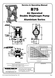
ITEM<br />
NO. PART NUMBER DESCRIPTION QTY.<br />
1 031.012.000 SLEEVE & SPOOL SET 1<br />
2 070.006.170 BEARING 2<br />
3 095.043.156 BODY, AIR VALVE 1<br />
4 095.073.001 ASSEMBLY, PILOT VALVE 1<br />
4-A 095.070.558 BODY, PILOT VALVE 1<br />
4-B 560.023.360 O-RING (SPOOL) 2<br />
4-C 560.033.360 O-RING 4<br />
4-D 675.037.080 RETAINING RING 1<br />
4-E 755.025.000 SLEEVE, PILOT VALVE 1<br />
4-F 775.026.000 SPOOL, PILOT VALVE 1<br />
5 114.002.156 INTERMEDIATE 1<br />
6 115.020.080 BRACKET, FOOT 2<br />
7 115.021.080 BRACKET, FOOT 2<br />
8 132.002.360 BUMPER, DIAPHRAGM PLATE 2<br />
9 132.014.358 BUMPER, AIR VALVE 2<br />
10 135.016.162 BUSHING, THREADED,<br />
W/ O-RING 560.001.360 2<br />
11 165.011.157 CAP, END 2<br />
12 170.012.330 CAPSCREW,<br />
HEX HEAD 1/2-13 UNC X 2.00 8<br />
13 170.023.330 CAPSCREW, HEX HEAD 4<br />
14 170.024.330 CAPSCREW,<br />
HEX HEAD, 7/16-14 X 1 8<br />
15 170.032.330 CAPSCREW, HEX HEAD 8<br />
16 170.045.330 CAPSCREW HEX HEAD 4<br />
17 170.066.330 CAPSCREW,<br />
HEX, 1/2-13 X 2.25 36<br />
18 172.001.330 CAPSCREW, SOCKET 12<br />
19 196.003.155 CHAMBER, INNER 2<br />
20 196.004.155 CHAMBER, OUTER 2<br />
21 286.018.354 DIAPHRAGM 2<br />
286.018.357 DIAPHRAGM 2<br />
286.018.360 DIAPHRAGM 2<br />
286.018.365 DIAPHRAGM 2<br />
22 312.015.155 ELBOW, SUCTION 2<br />
23 312.016.155 ELBOW, DISCHARGE 2<br />
24 334.020.000 FLANGE, FOLLOWER 4<br />
25 338.008.360 FLAP VALVE 4<br />
338.008.365 FLAP VALVE 4<br />
338.011.354 FLAP VALVE 4<br />
338.011.356 FLAP VALVE 4<br />
338.011.357 FLAP VALVE 4<br />
26 360.010.425 GASKET, END CAP 2<br />
27 360.013.379 GASKET, FLANGE 4<br />
360.013.384 GASKET, FLANGE 4<br />
28 360.014.379 GASKET, FLANGE 4<br />
360.014.384 GASKET, FLANGE 4<br />
29 360.021.000 GASKET 4<br />
<strong>Design</strong> <strong>Level</strong> 7<br />
x75afvmdl7sm-rev0411 Page 13
ITEM<br />
NO. PART NUMBER DESCRIPTION QTY.<br />
30 360.041.379 GASKET, VALVE BODY 1<br />
31 360.048.425 GASKET, VALVE BODY 1<br />
32 518.014.156 MANIFOLD 2<br />
33 545.007.330 NUT, HEX - 7/16-14 20<br />
34 545.008.330 NUT, HEX, 1/2-13 24<br />
35 547.002.110 NUT, STOP 8<br />
36 547.006.330 NUT, STOP 2<br />
37 560.001.360 O-RING 2<br />
38 560.020.360 O-RING 6<br />
39 560.022.360 O-RING 2<br />
40 570.002.360 PAD, HINGE 4<br />
570.002.365 PAD, HINGE 4<br />
41 570.012.371 PAD, WEAR 2<br />
42 612.014.000 PLATE, DIAPHRAGM 2<br />
43 612.015.156 PLATE, OUTER DIAPHRAGM 2<br />
44 618.003.330 PLUG, PIPE, 1/4 2<br />
45 618.004.330 PIPE, PLUG 2<br />
46 620.011.114 PLUNGER, ACTUATOR 2<br />
47 670.006.115 RETAINER, FLAP VALVE 4<br />
48 685.008.120 ROD, DIAPHRAGM 1<br />
49 720.004.360 SEAL, U-CUP 2<br />
50 722.007.115 SEAT, FLAP VALVE 4<br />
51 807.016.330 7/16-14 X 3 STUD 12<br />
52 807.017.330 7/16-14 X 3 STUD 8<br />
53 807.018.110 STUD, 1/4-20 8<br />
54 900.003.330 WASHER, LOCK, 1/2 8<br />
55 900.006.330 WASHER, LOCK - 7/16 1 2<br />
56 901.006.330 WASHER, FLAT, 1/2 12<br />
57 901.011.180 WASHER 12<br />
58 901.013.180 WASHER, SEALING 2<br />
59 901.023.330 WASHER, FLAT 2<br />
NOT SHOWN:<br />
031.019.156. MAIN AIR VALVE ASSEMBLY 1<br />
(includes items 10, 11, 13, 14, 15 &16)<br />
901.035.115. WASHER FLAT 8<br />
(used w/Santoprene <strong>Flap</strong>s)<br />
x75afvmdl7sm-rev0411 Page 14
x75afvmdl7sm-rev0411 Page 15<br />
USE WITH<br />
HDF4-M ONLY<br />
32<br />
21<br />
20<br />
22<br />
29<br />
19<br />
30<br />
4-A<br />
4-D<br />
31<br />
3<br />
16<br />
4-F<br />
4-E<br />
48<br />
10<br />
37<br />
46<br />
14<br />
34<br />
28<br />
35<br />
53<br />
47<br />
40<br />
50<br />
27<br />
52<br />
50<br />
51<br />
25<br />
33<br />
23<br />
24<br />
56<br />
17<br />
6<br />
4-B<br />
4-C<br />
15<br />
11<br />
8<br />
58<br />
42<br />
59<br />
36<br />
5<br />
26<br />
9<br />
38<br />
1<br />
45<br />
7<br />
39<br />
54<br />
12<br />
17<br />
55<br />
44<br />
28<br />
27<br />
49<br />
2<br />
41 43<br />
57<br />
18<br />
55<br />
13
Declaration of Conformity<br />
Manufacturer: IDEX <strong>Pump</strong> Technologies (Ireland) Ltd., • A Unit of IDEX Corporation<br />
R79, Shannon, Co Clare, Ireland<br />
Certifies that Air-Operated Double Diaphragm <strong>Pump</strong> Series: B75, <strong>X75</strong>, AVB75, AV<strong>X75</strong> and<br />
Pulsation Dampener models: PD25M, PD40M, PD50M & PD80M comply with comply with<br />
the European Community Directive 2006/42/EC on Machinery, according to Annex VIII.<br />
This product has used Harmonized Standard EN 809, <strong>Pump</strong>s and <strong>Pump</strong> Units for Liquids -<br />
Common Safety Requirements, to verify conformance.<br />
October 20, 2005<br />
Date of issue<br />
Signature of authorized person<br />
Des Monaghan Production & Tech. Manager<br />
Printed name of authorized person<br />
Title<br />
Date of revision<br />
May 27, 2010<br />
Revision <strong>Level</strong>: E
EC Declaration of Conformity<br />
In accordance with ATEX Directive 94/9/EC,<br />
Equipment intended for use in potentially explosive environments.<br />
Manufacturer: IDEX <strong>Pump</strong> Technologies (Ireland) Ltd.,<br />
A Unit of IDEX Corporation, R79, Shannon, Co Clare, IRELAND.<br />
Applicable Standard:<br />
EN13463-1: 2001,<br />
EN13463-5: 2003<br />
AODD <strong>Pump</strong>s Equipped with <strong>Aluminium</strong><br />
Type Examination Certificate: KEMA 09ATEX0072 X<br />
AODD (Air-Operated Double Diaphragm) <strong>Pump</strong>s<br />
EC Type Examination Certificate No. <strong>Pump</strong>s: KEMA 09ATEX0071 X<br />
KEMA Quality B.V.<br />
Utrechtseweg 310<br />
6812 AR Arnhem, The Netherlands<br />
Production and Technical Manager<br />
DATE/APPROVAL/TITLE:<br />
27 MAY 2010