Digital Circuit And Logic Design I Decoder and encoder
Digital Circuit And Logic Design I Decoder and encoder
Digital Circuit And Logic Design I Decoder and encoder
You also want an ePaper? Increase the reach of your titles
YUMPU automatically turns print PDFs into web optimized ePapers that Google loves.
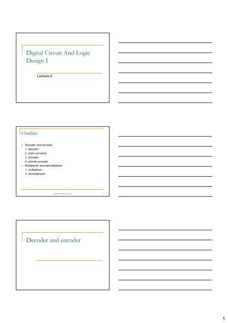
<strong>Digital</strong> <strong>Circuit</strong> <strong>And</strong> <strong>Logic</strong><br />
<strong>Design</strong> I<br />
Lecture 6<br />
Outline<br />
• <strong>Decoder</strong> <strong>and</strong> <strong>encoder</strong><br />
1. decoder<br />
2. code converter<br />
3. <strong>encoder</strong><br />
4. priority <strong>encoder</strong><br />
• Multiplexer <strong>and</strong> demultiplexer<br />
1. multiplexer<br />
2. demultiplexer<br />
Panupong Sornkhom, 2005/2 2<br />
<strong>Decoder</strong> <strong>and</strong> <strong>encoder</strong><br />
1
1. <strong>Decoder</strong><br />
• A code is a string of<br />
several bits. With an n-bit<br />
code, it is possible to<br />
represent 2 n unique<br />
values<br />
• The devices that translate<br />
the n-bit pattern into one<br />
of the 2 n possible values<br />
are called decoders<br />
Pictures from text book Introduction to <strong>Logic</strong> design<br />
Panupong Sornkhom, 2005/2 4<br />
1. <strong>Decoder</strong> (cont.)<br />
‘138 MSI<br />
component<br />
Pictures from text book <strong>Digital</strong> <strong>Logic</strong> pocket data book<br />
Panupong Sornkhom, 2005/2 5<br />
1. <strong>Decoder</strong> (cont.)<br />
4-to-16 decoder implement<br />
by using 3-to-8 decoders<br />
5-to-32 decoder implement by<br />
using 3-to-8 decoders <strong>and</strong> 2-to-4<br />
decoder<br />
Panupong Sornkhom, 2005/2 6<br />
2
1. <strong>Decoder</strong> (cont.)<br />
• <strong>Decoder</strong>s can be used to<br />
implement any function in<br />
canonical sum or canonical<br />
product form.<br />
• All that is needed is external<br />
logic required to OR minterms<br />
for canonical sum expression or<br />
to AND maxterms for canonical<br />
product expression.<br />
Using 3-to-8 decoder to<br />
implement logic function F<br />
<strong>and</strong> G<br />
Panupong Sornkhom, 2005/2 7<br />
2. Code converter<br />
• A code converter is a<br />
combinational circuit that<br />
translates the input code<br />
word into the corresponding<br />
new code word<br />
• For example, BCD-to-7-<br />
segment decoder <strong>and</strong> BCDto-excess-3<br />
code converter<br />
Pictures from text book Introduction to<br />
<strong>Logic</strong> design<br />
Pictures from text book DDPP<br />
Panupong Sornkhom, 2005/2 8<br />
2. Code converter (cont.)<br />
‘47 MSI<br />
component<br />
Pictures from text book <strong>Digital</strong> <strong>Logic</strong> pocket data book<br />
Panupong Sornkhom, 2005/2 9<br />
3
3. Encoder<br />
• An <strong>encoder</strong> performs the<br />
reverse function of a decoder.<br />
The 2 n -to-n decoder generates<br />
an n-bit code word as a<br />
function of the combination of<br />
values on its 2 n inputs<br />
• Usually only one of the inputs<br />
is 1 <strong>and</strong> all others are 0. The<br />
output is a binary code word<br />
corresponding to the input.<br />
• Because <strong>encoder</strong>s can be built<br />
easily, <strong>encoder</strong> ICs are not<br />
available as off-the-shelf<br />
components<br />
Pictures from text book Introduction to <strong>Logic</strong> design<br />
Panupong Sornkhom, 2005/2 10<br />
4. Priority <strong>encoder</strong><br />
• If more than one input is 1 at<br />
‘147 MSI component<br />
any time, the <strong>encoder</strong><br />
generally will not produce a<br />
valid output<br />
• Nevertheless, there are<br />
exceptions. The so-called<br />
priority <strong>encoder</strong>s allow more<br />
than one of their inputs to be<br />
active at any time.<br />
• Each input has priority<br />
assigned to it. The code word<br />
produced as the output<br />
corresponds to that of the<br />
highest-priority input among all<br />
the inputs that are active<br />
Pictures from text book <strong>Digital</strong> <strong>Logic</strong> pocket data book<br />
Panupong Sornkhom, 2005/2 11<br />
Multiplexer <strong>and</strong> demultiplexer<br />
4
1. Multiplexer<br />
• Multiplexing is the process of<br />
channeling information from<br />
one of several sources to a<br />
single destination<br />
• A multiplexer (selector) is<br />
thus a switch connecting one<br />
of its several inputs to the<br />
output. A set of n control<br />
inputs is needed to select<br />
one of the 2 n inputs<br />
Pictures from text book<br />
Introduction to <strong>Logic</strong><br />
design<br />
Panupong Sornkhom, 2005/2 13<br />
1. Multiplexer (cont.)<br />
• Multiplexers can be<br />
stacked to produce 2 n -<br />
to-1multiplexer.<br />
16-to-4 multiplexer implement<br />
by using 4-to-1 multiplexer<br />
Panupong Sornkhom, 2005/2 14<br />
1. Multiplexer (cont.)<br />
• Multiplexer can be used to<br />
realize any logic function F<br />
• For example, F =<br />
Σ A,B,C (2,3,5,7)<br />
• It is possible to reduce the<br />
number of input on the<br />
multiplexer to implement this<br />
function<br />
• We can partition the truth<br />
table based on the values of<br />
B <strong>and</strong> C (this is often called<br />
folded-table method)<br />
Pictures from text book<br />
Introduction to <strong>Logic</strong><br />
design<br />
Panupong Sornkhom, 2005/2 15<br />
5
1. Multiplexer (cont.)<br />
Pictures from text book<br />
Introduction to <strong>Logic</strong> design<br />
Panupong Sornkhom, 2005/2 16<br />
2. Demultiplexer<br />
• Demultiplexing is the reverse<br />
of multiplexing. That is,A<br />
demultiplexer (distributor)<br />
distributes its input signal to<br />
one of its several outputs<br />
• In fact, a decoder with an<br />
enable input can be used as<br />
demultiplexer.<br />
Pictures from Introduction to <strong>Logic</strong> design<br />
Panupong Sornkhom, 2005/2 17<br />
6


